Gear Souvenir
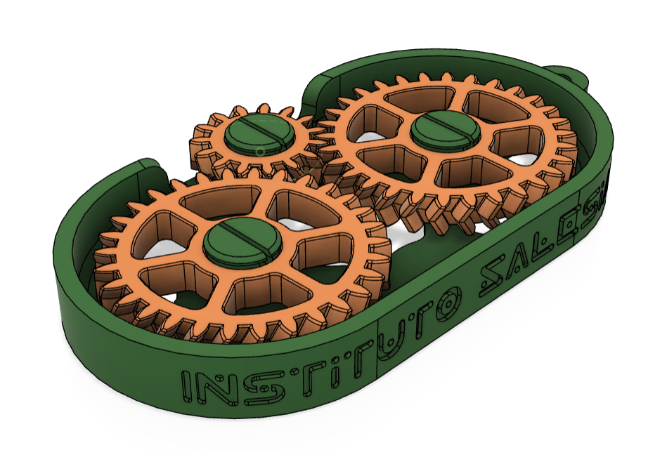
This chapter designs a simple gear souvenir while introducing gear operation and modelling.
1. Spur, Helical and Herringbone Gears
The model uses herringbone gears, which look different from familiar Tamiya spur gears.
- Spur gear: a cylindrical gear whose teeth run parallel to its axis. It is widely used and comparatively easy to manufacture.
- Helical gear: angled teeth engage gradually, giving smoother operation and higher load capacity, but they produce axial thrust.
- Herringbone gear: two opposing helical tooth sets meet in the centre. Their axial thrusts cancel, though conventional manufacture is more difficult.
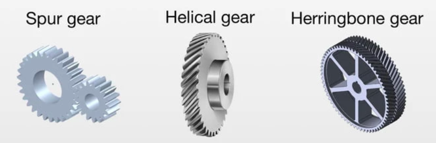
Herringbone gears carry more load than comparable spur gears, self-centre and avoid the axial movement of a single helical gear, so the driven gear may not need a thrust collar or retaining ring. Additive manufacturing removes much of their traditional manufacturing difficulty, making them particularly attractive for 3D-printed mechanisms.
2. Generate the Gears
A typical FDM printer with a 0.4 mm nozzle cannot reproduce extremely fine teeth reliably; approximately module 0.8 is a practical lower bound for this type of exercise. We will use module 1 and create two 30-tooth gears plus one 15-tooth gear.
2.1 Gear One: 30 Teeth
2.1.1 Generate the Gear
Open Create → Helical Gear+.
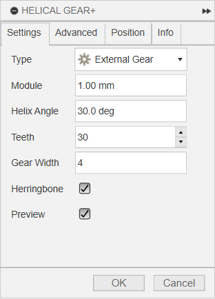

Set Module = 1 mm, Helix Angle = 30°, Teeth = 30, Gear Width = 4 mm, and enable Herringbone. On the second page choose Standard = Radial and keep the other values.
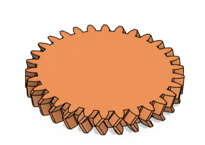
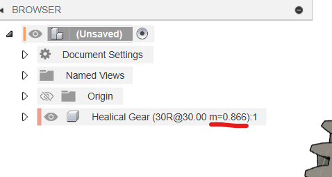
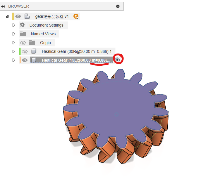
The Browser reports an effective normal module of about 0.866 (), because the tooth geometry is projected relative to the helical angle. The radial pitch circle is nevertheless 30 mm in diameter.
2.1.2 Add Backlash
⚠️WARNING
The generated gear cannot be printed as-is: without clearance, printed teeth will bind. Backlash must be added.
One method is to enter Backlash, Addendum and Dedendum in the add-in, but the generated gear has no editable feature history. A more adjustable method is to offset all tooth faces inwards.
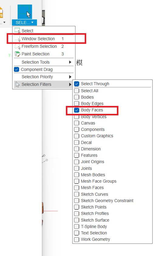
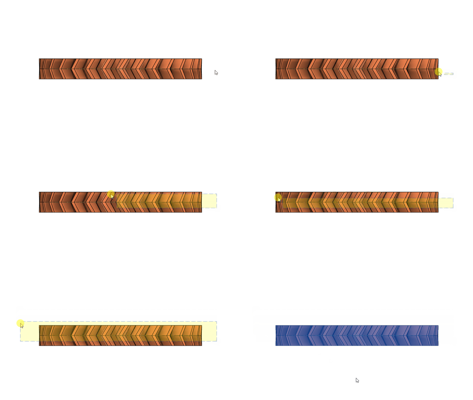
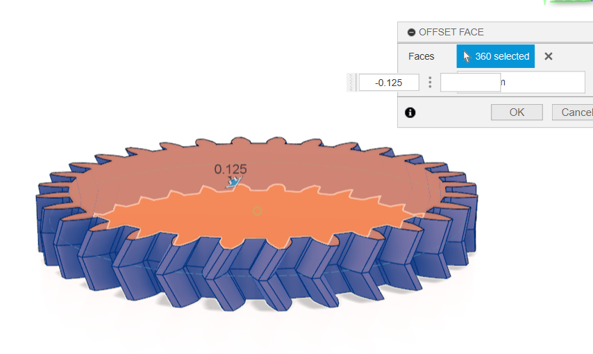
Set Select to Window Selection (shortcut 1) and under Selection Filters leave only Body Faces. In Front or Side view, drag a crossing window from lower-right to upper-left across the teeth without touching the top or bottom faces.
📝NOTE
A left-to-right window selects only objects completely inside it. A right-to-left crossing window also selects objects that merely touch or cross the window.
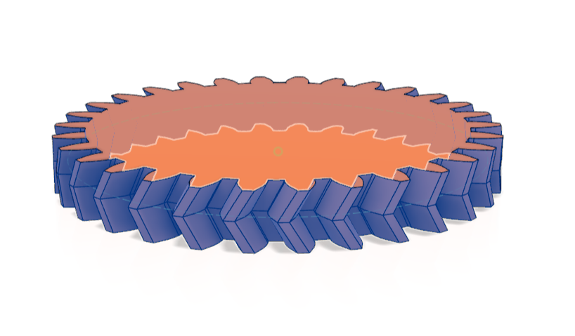
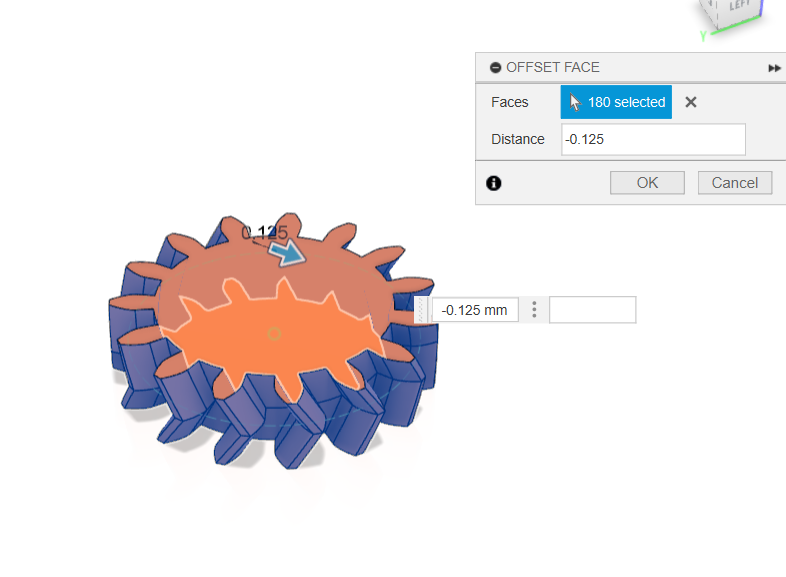
Rotate the view and verify that only tooth side faces are selected. Run Offset Face with -0.125 mm.
2.1.3 Modify the Gear
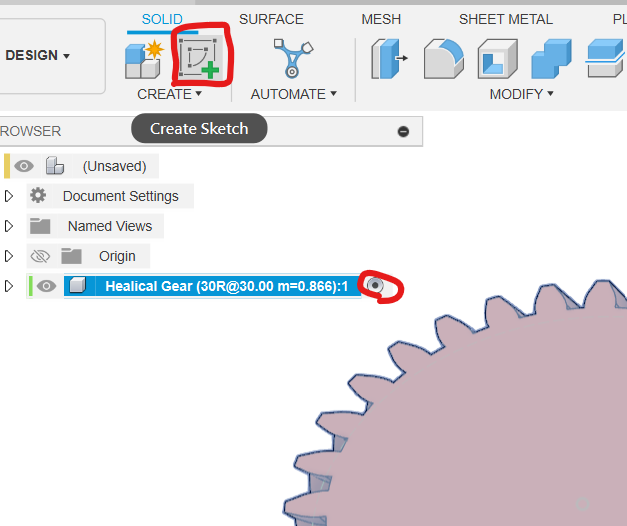
Activate the gear component and sketch on its face.
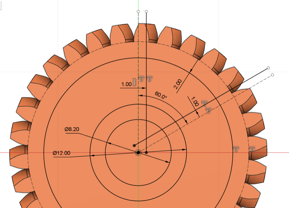
Draw a circle through the tooth roots and press X to make it construction geometry. Offset it by 2 mm. Draw vertical and 60° construction lines and offset both by 1 mm. Finally draw Ø8.2 and Ø12 mm concentric circles.
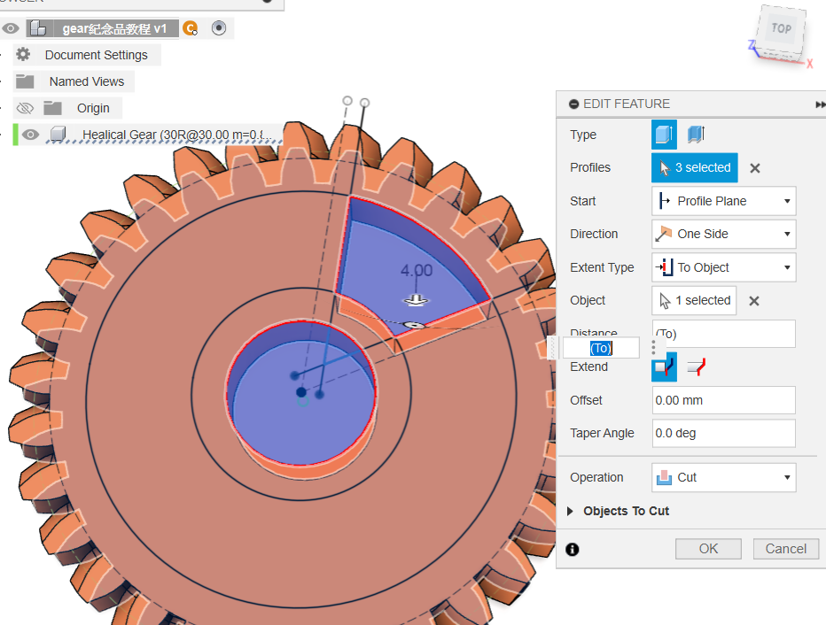
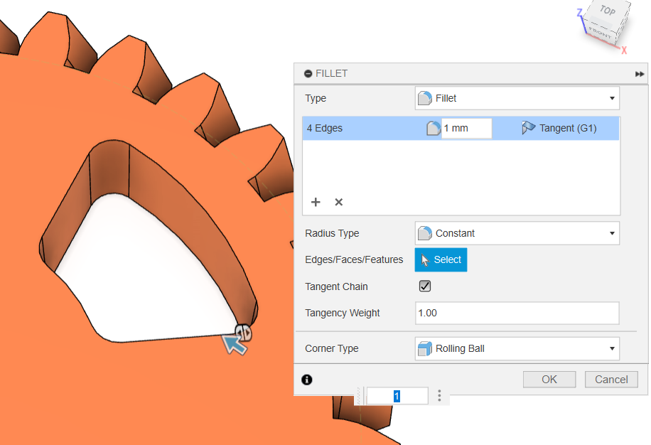
Press E and cut the profile with Extent To Object through the bottom. Apply 1 mm fillets to the four edges.
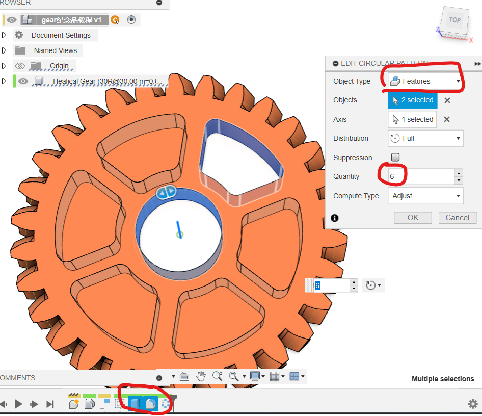
Use Circular Pattern, Object Type Features, selecting the cut and fillet features. Choose the Z-axis (or pitch-circle axis) and Quantity 6. If computation fails, try Optimized or Identical instead of Adjust.
2.2 Gear Two: 15 Teeth
2.2.1 Generate the Gear
Reactivate the top level and hide the 30-tooth gear.
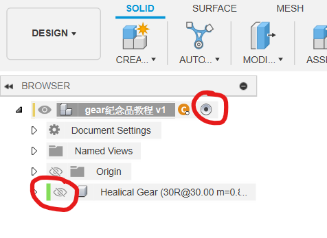
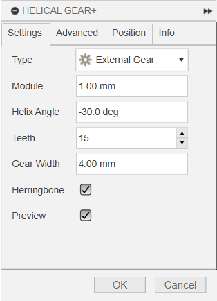
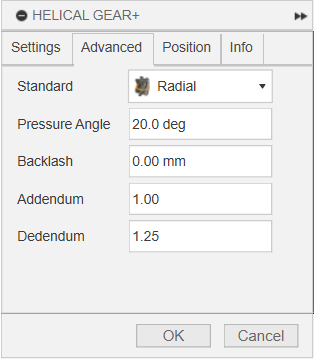
Use Helical Gear+ with Module = 1 mm, Helix Angle = -30°, Teeth = 15, Gear Width = 4 mm, Herringbone enabled and Standard = Radial. Meshing helical gears require compatible helix angles; here the opposite signs let the two generated gears mesh correctly.
2.2.2 Add Backlash
Select the small gear's tooth side faces and offset them by -0.125 mm, as above.
2.2.3 Add the Centre Hole
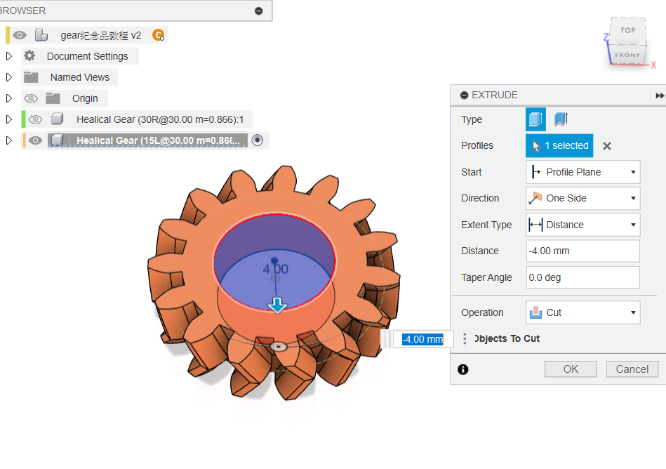
Confirm the effective module matches the first gear at about 0.866. Activate the small gear, sketch an 8.2 mm circle on its face, and cut with To Object through the bottom.
3. Create the Housing
3.1 Basic Housing
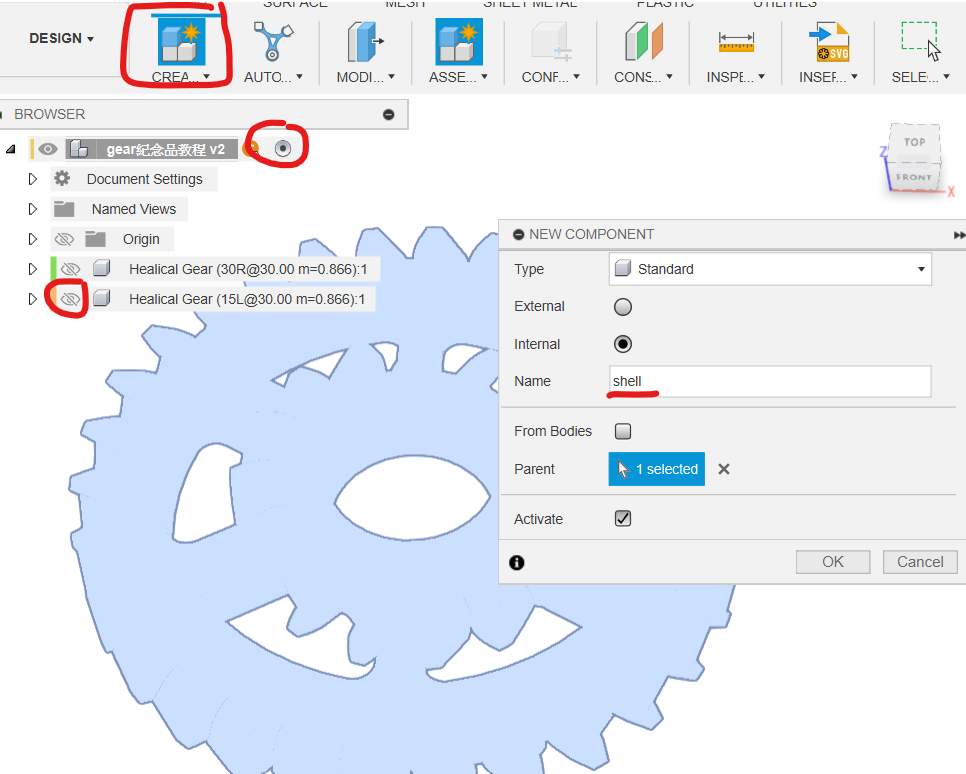
Reactivate the top level, hide the small gear and create a component named Shell. On Top, create a centre-to-centre slot with 18 mm radius and 33 mm centre distance, constrained to the origin with Midpoint.
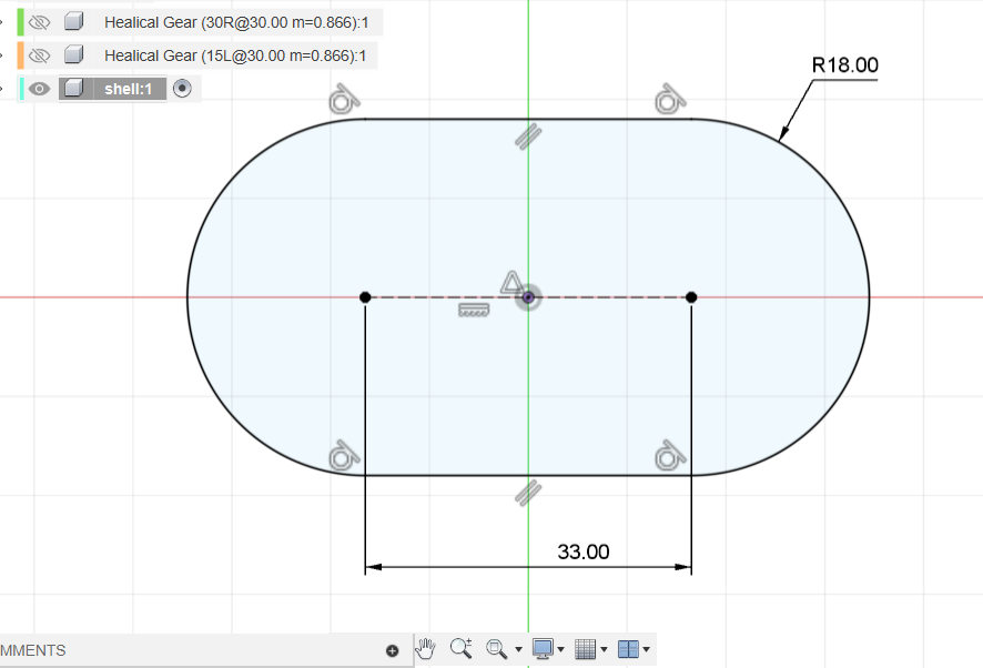
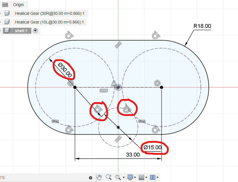
The large and small pitch diameters are 30 and 15 mm. Draw a Ø30 mm circle at each slot centre. Draw a Ø15 mm circle elsewhere, then constrain it tangent to both Ø30 circles. Offset the slot outward by 2 mm for the wall.
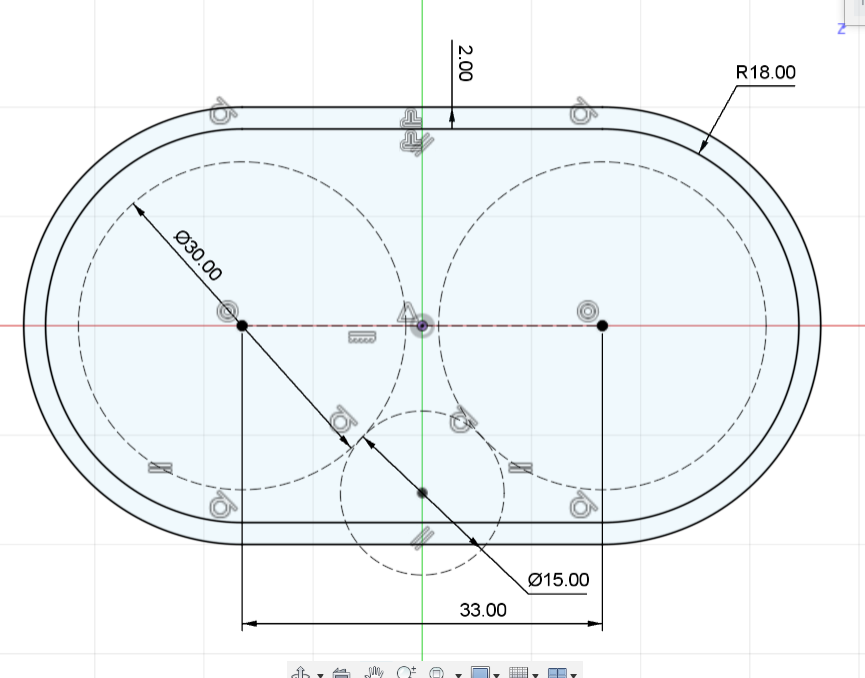
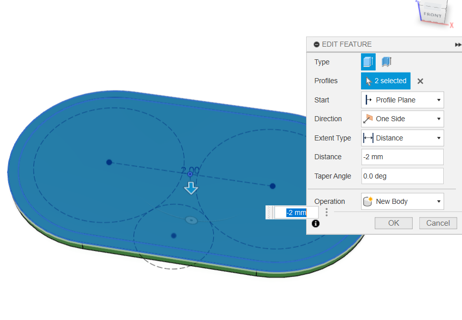
Extrude all sketch regions downward by 2 mm. Show Sketch1 and extrude the wall upward by 6 mm.
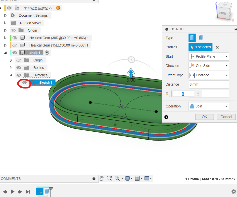
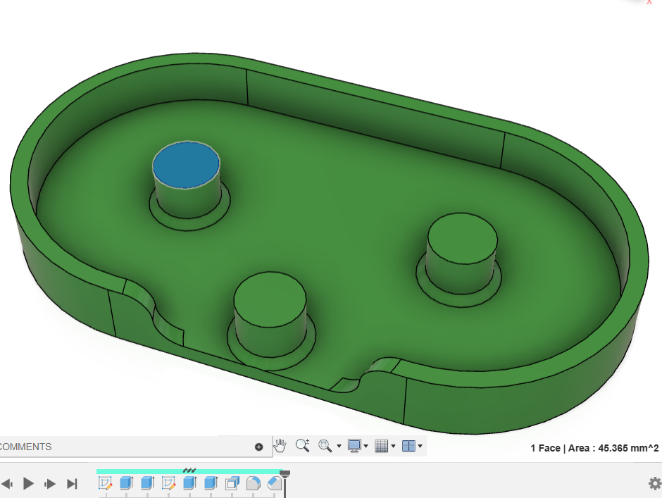
Hide Sketch1, sketch on the housing interior, show Sketch1 temporarily and press P to project the three circle centres, then hide it again.
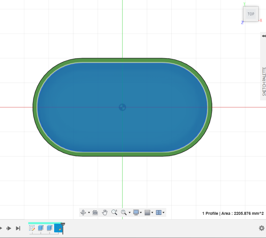
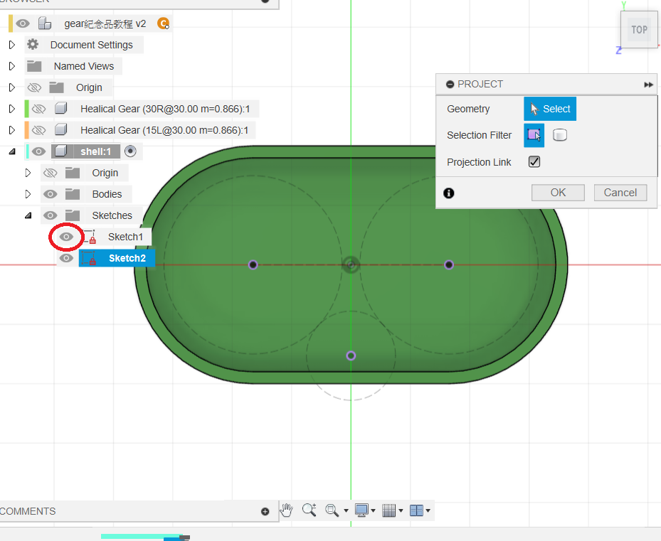
Draw a Ø7.6 mm circle at each centre and an additional Ø15 mm circle at the middle centre. Extrude the three small circles with To Object up to the housing height.
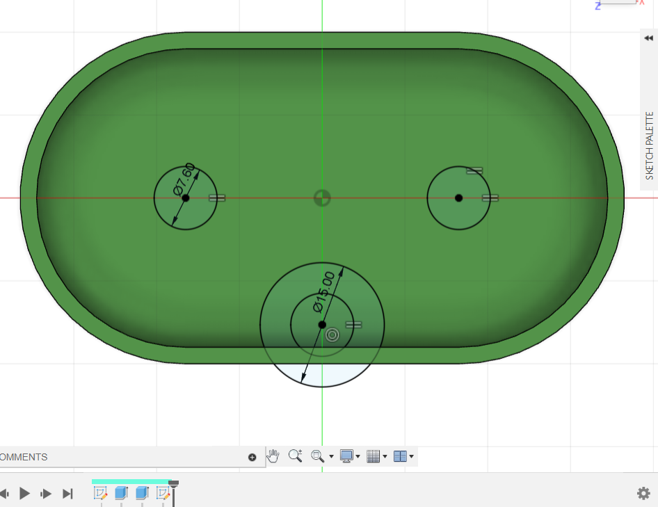
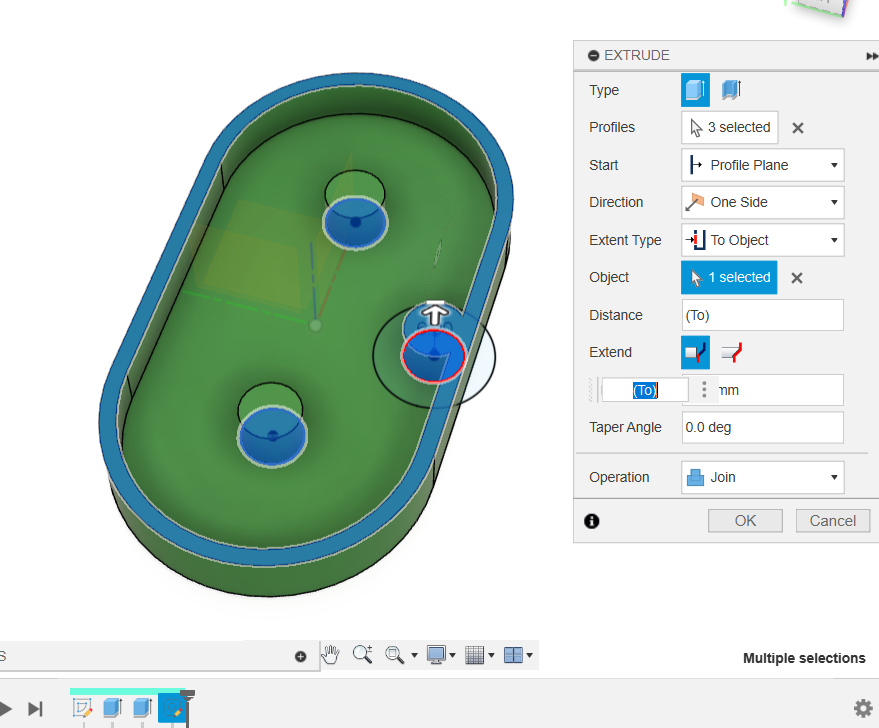
Show Sketch2, select the Ø15 mm circle and cut the middle housing region with To Object.
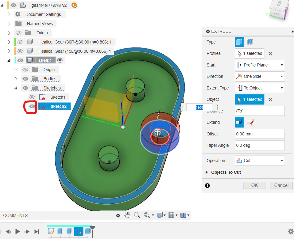
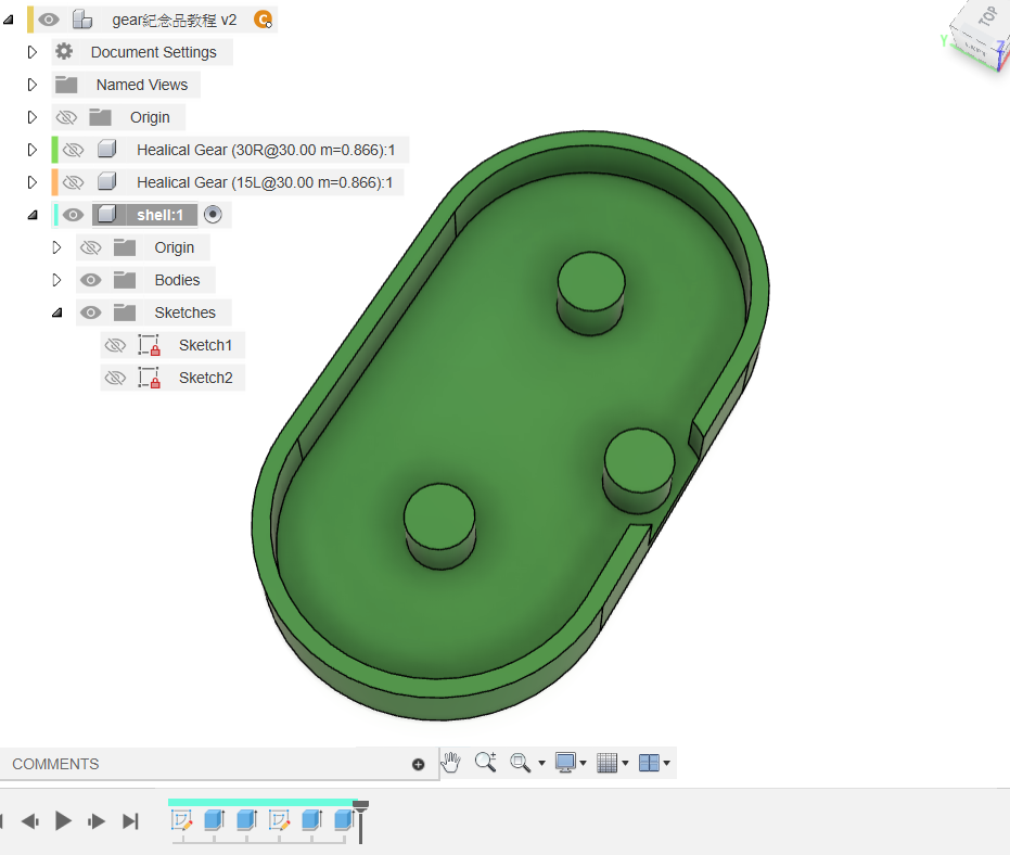
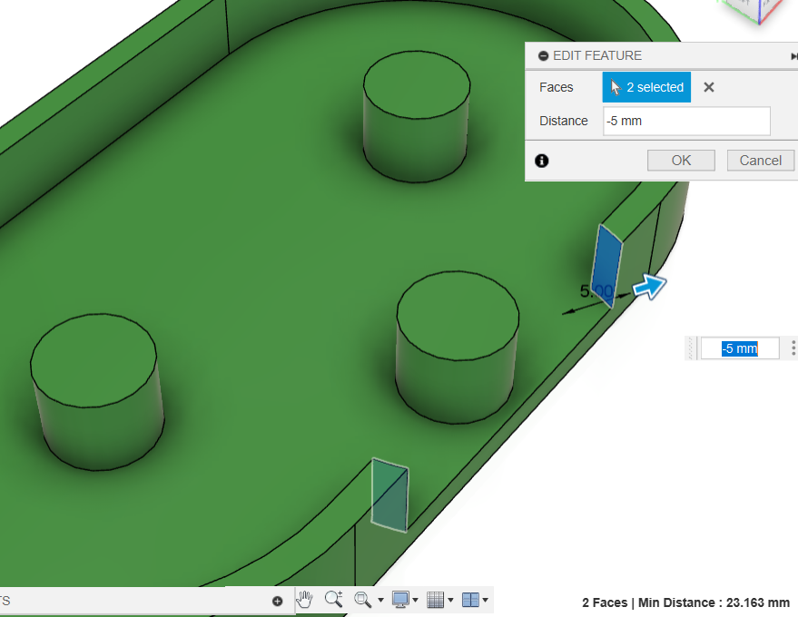
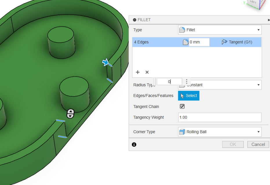
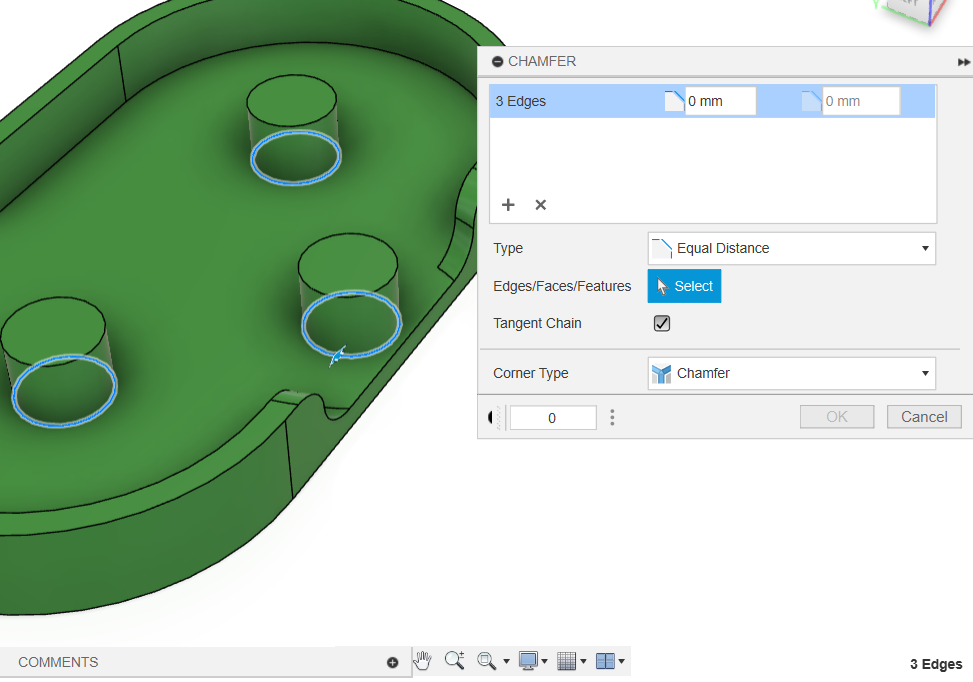
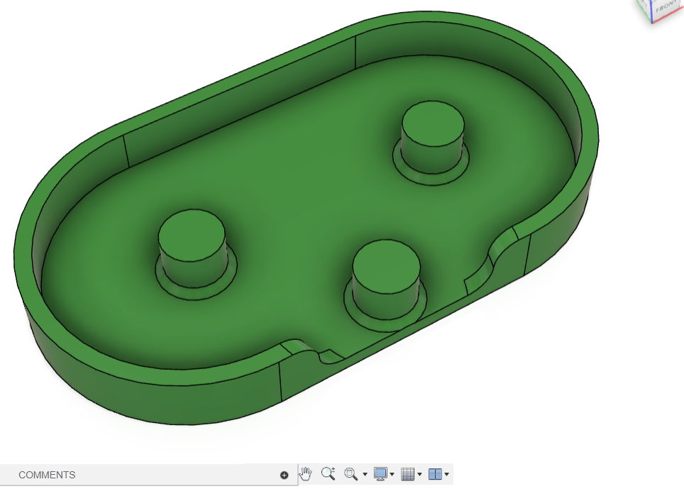
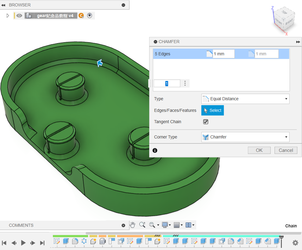
Offset the newly cut face outward by 5 mm, apply 3 mm fillets to the four edges, and add a 1 mm chamfer at the shaft-to-base junction to strengthen this vulnerable layer-line transition.
3.2 Add Retaining Clips
Sketch on the top of one shaft and project all three shaft faces.
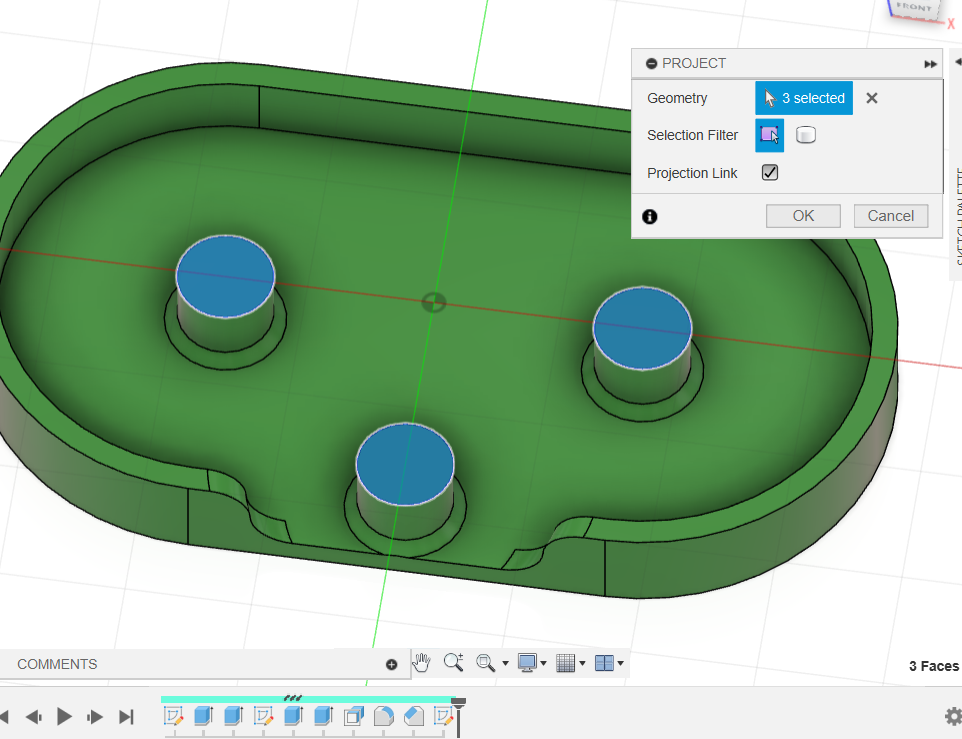
Offset each outer circle by 0.4 mm. Add a construction line through its centre, then draw two lines across the circumference and constrain them Parallel and Symmetric to form a 0.6 mm slot. Repeat for all three shafts, linking dimensions where practical.
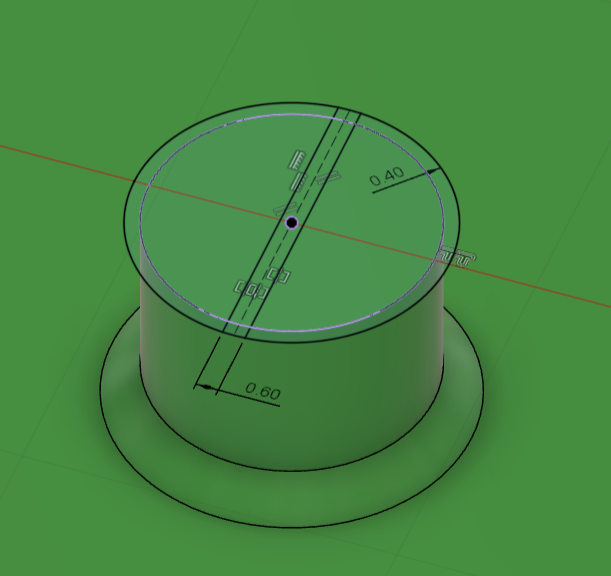
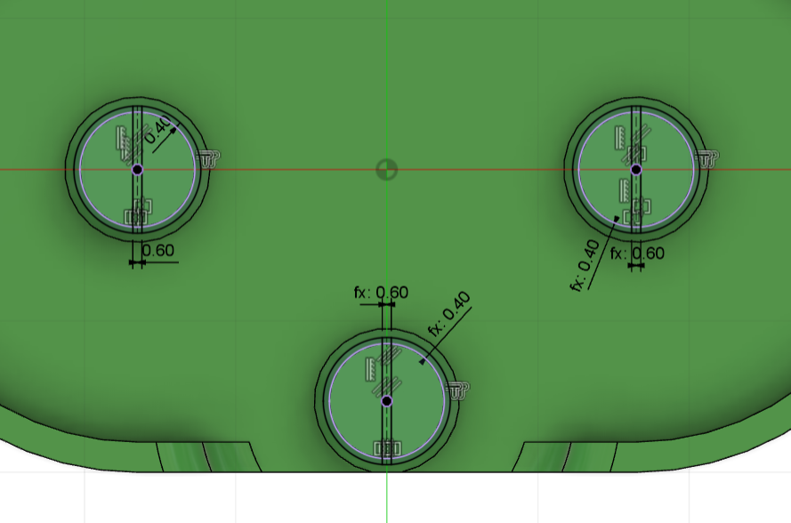
Extrude the three offset circles downward by 0.8 mm.
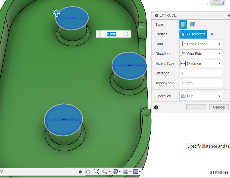
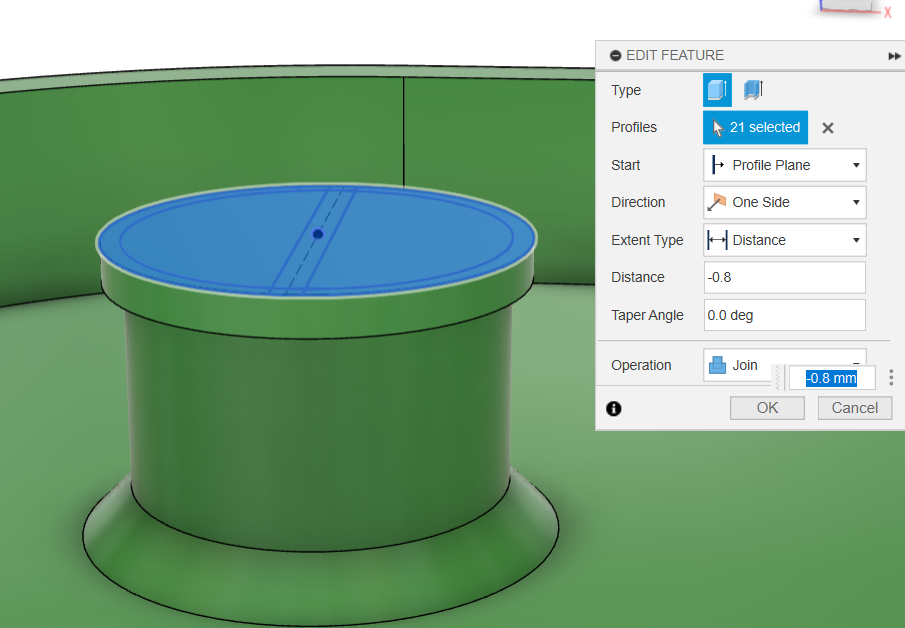
Chamfer the rings by 0.5 mm so gears slide on but resist coming off. Cut each 0.6 mm slot down 5.5 mm so the shaft can flex during assembly.
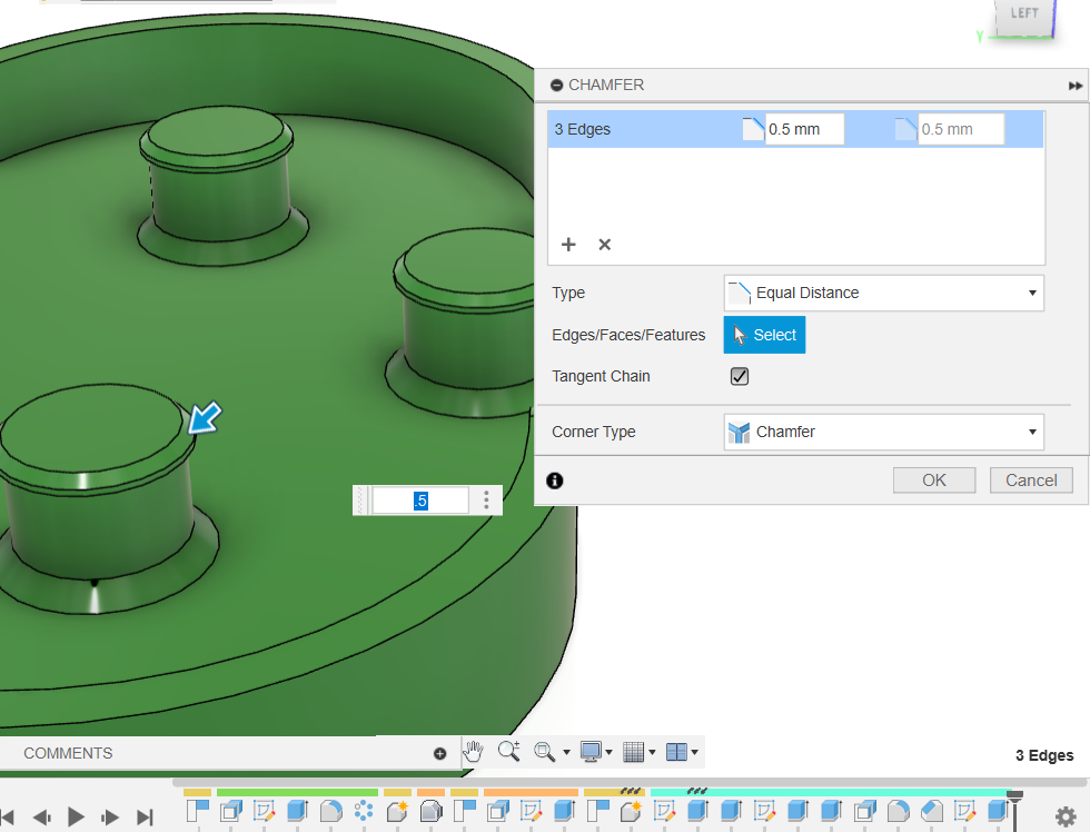
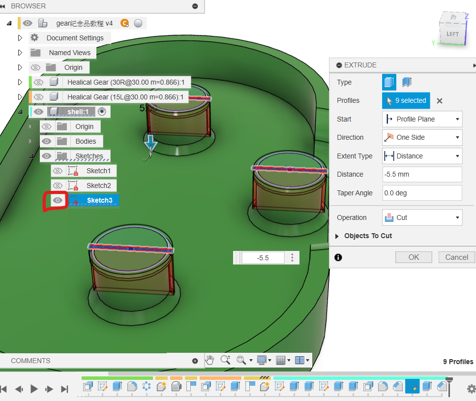
Add a 1 mm strengthening chamfer along the vertically printed housing wall.
3.3 Add a Keyring Loop
Sketch at the housing centre and project the relevant shaft centre.
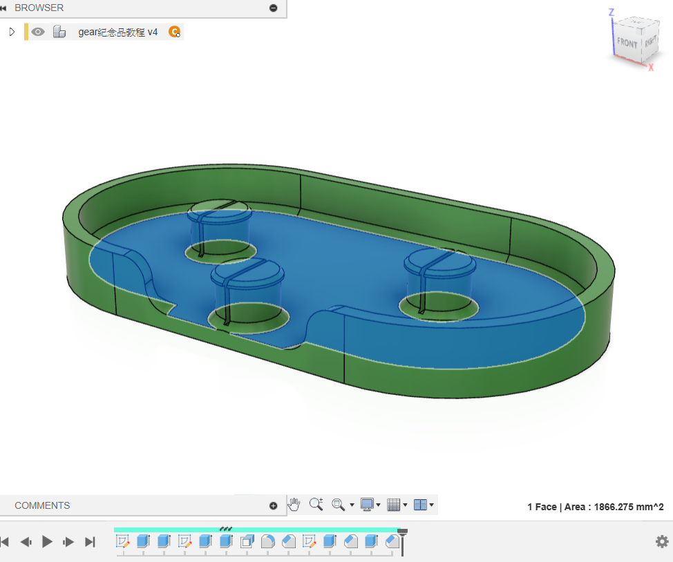
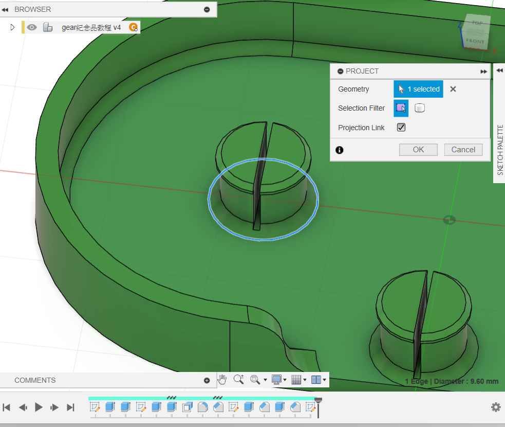
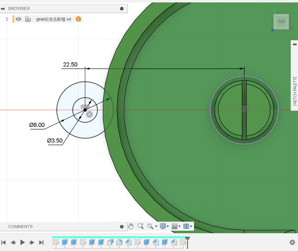
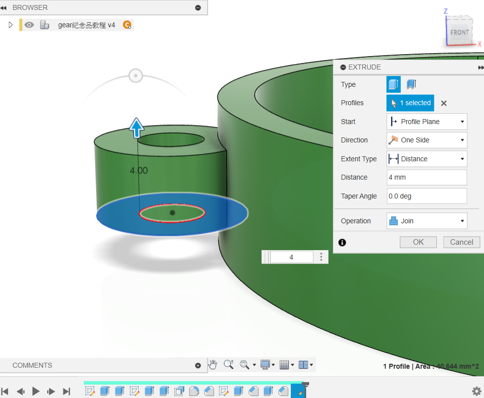
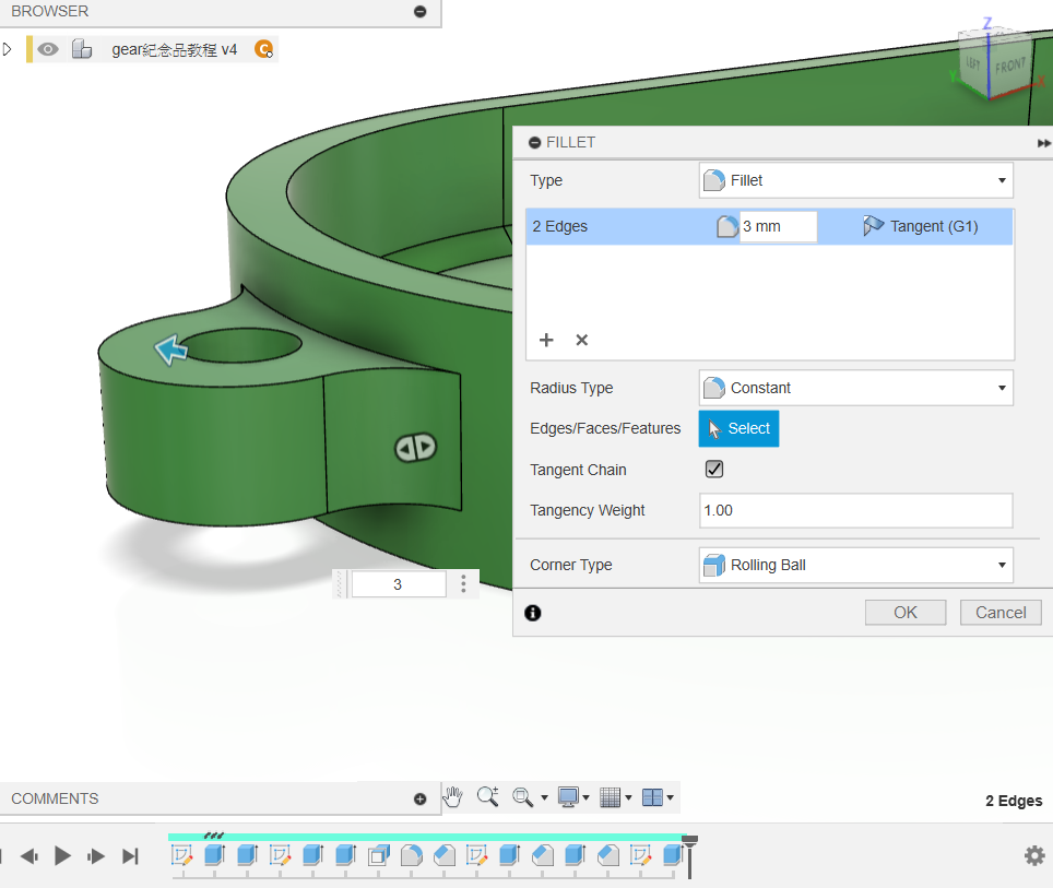
Draw Ø3.5 and Ø8 mm circles with their centre 22.5 mm from the projected shaft. Extrude upward by 4 mm and apply a 3 mm fillet.
4. Assemble and Simulate
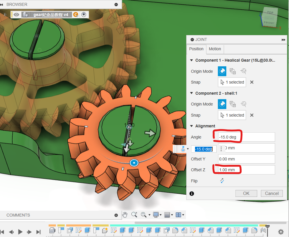
Reactivate the top level and show the hidden gears. Press J, select the gear and shaft faces, offset the gear downward by 1 mm so it passes the clip, and choose Revolute motion.
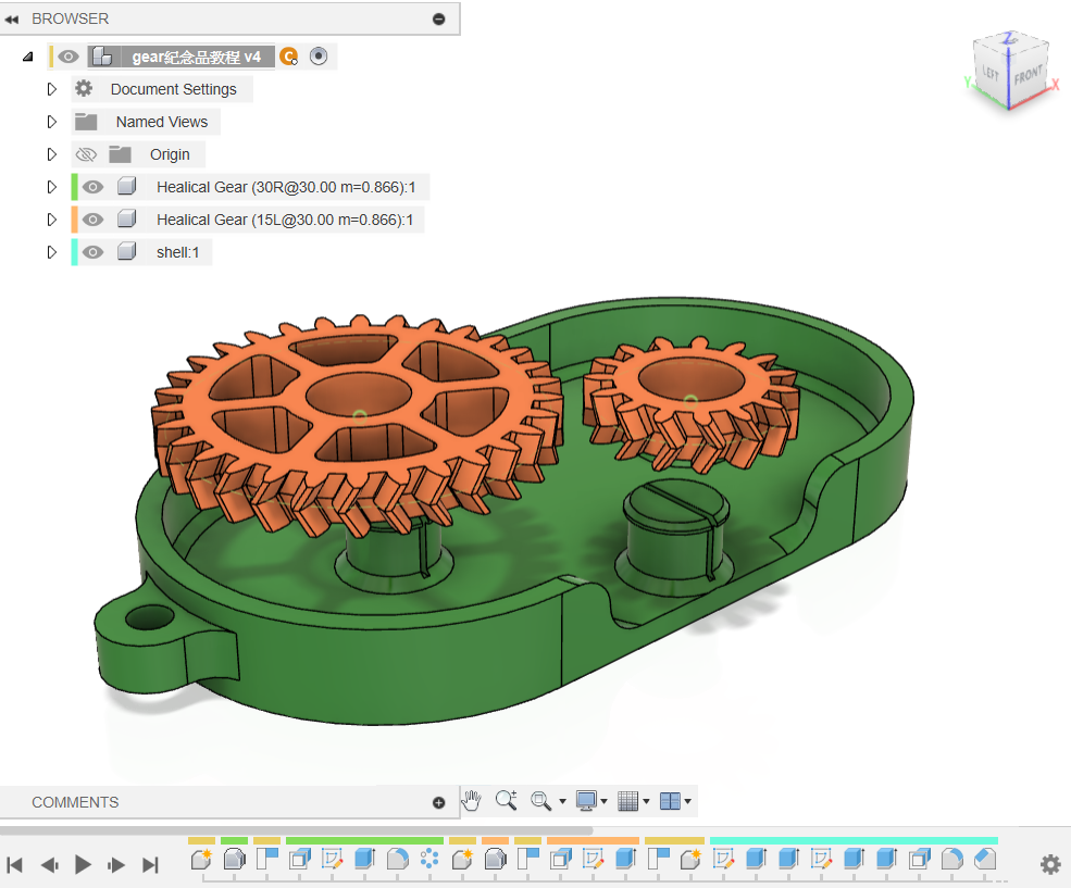
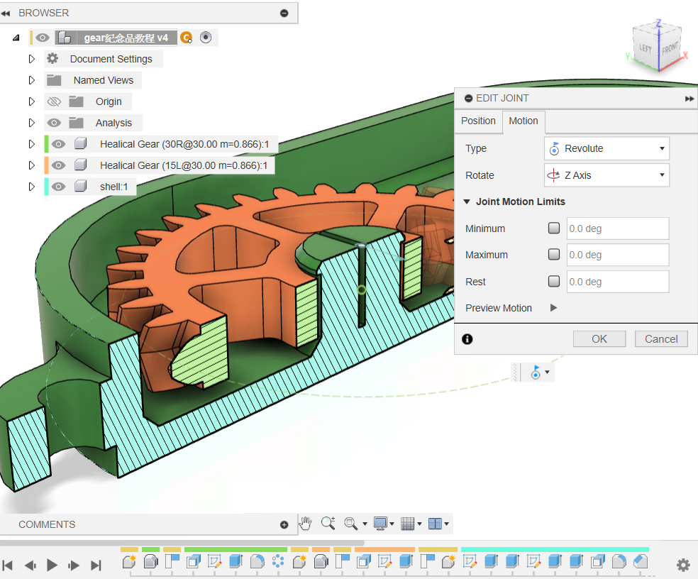
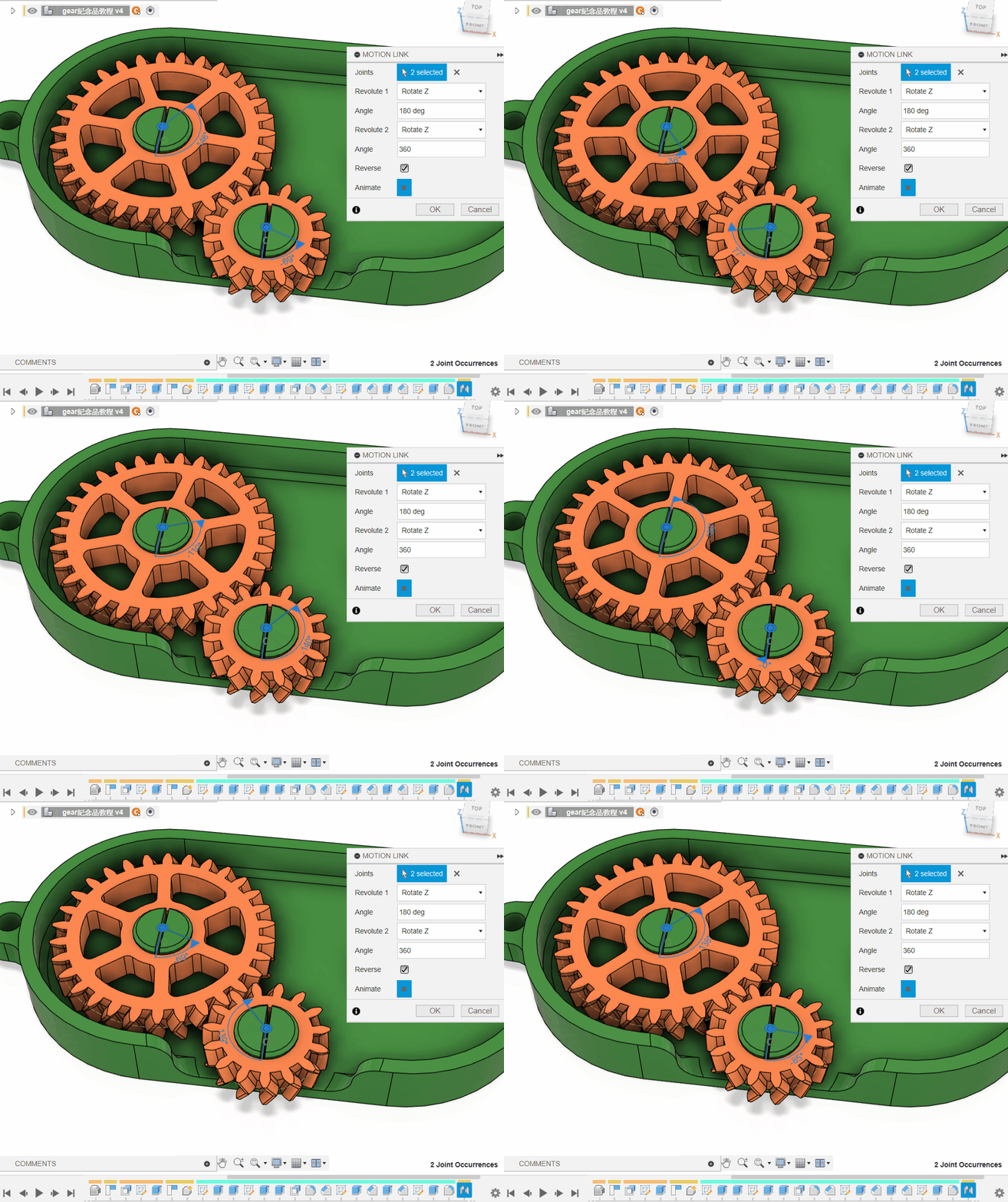
Joint the small gear similarly with Z Offset 1 mm and Angle 15° so its teeth mesh. Search for Motion Link, select both joint icons and define the 2:1 relationship: when the large gear turns 180°, the small one turns 360°. Enable Reverse for opposite directions.
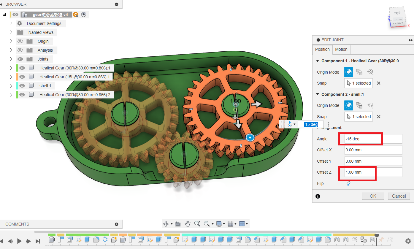
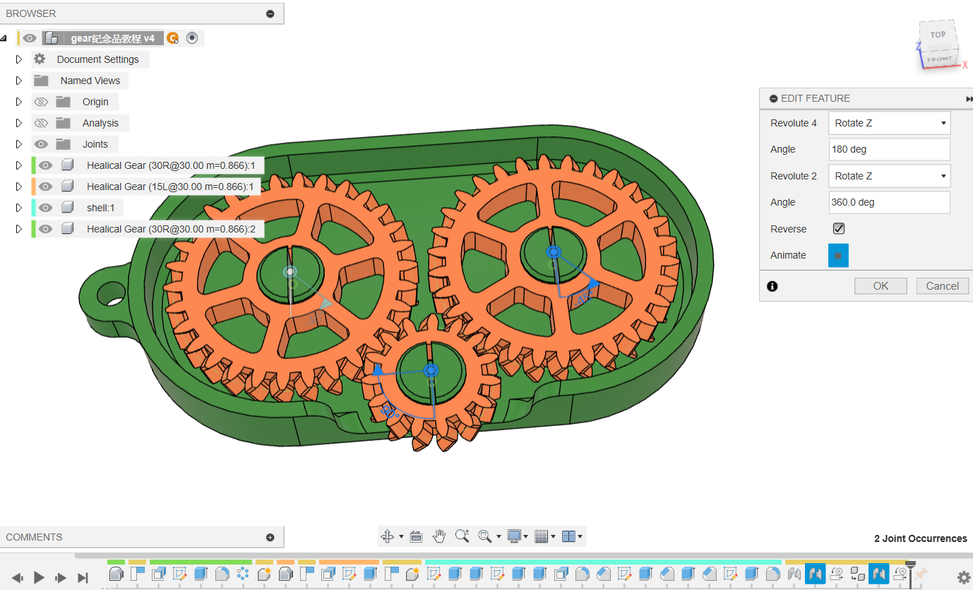
Copy the large gear, joint it to the remaining shaft with the same 15° rotation and 1 mm Z offset, and create another reversed 2:1 Motion Link. Ground the housing to simulate the complete mechanism.
5. Optional Curved Text
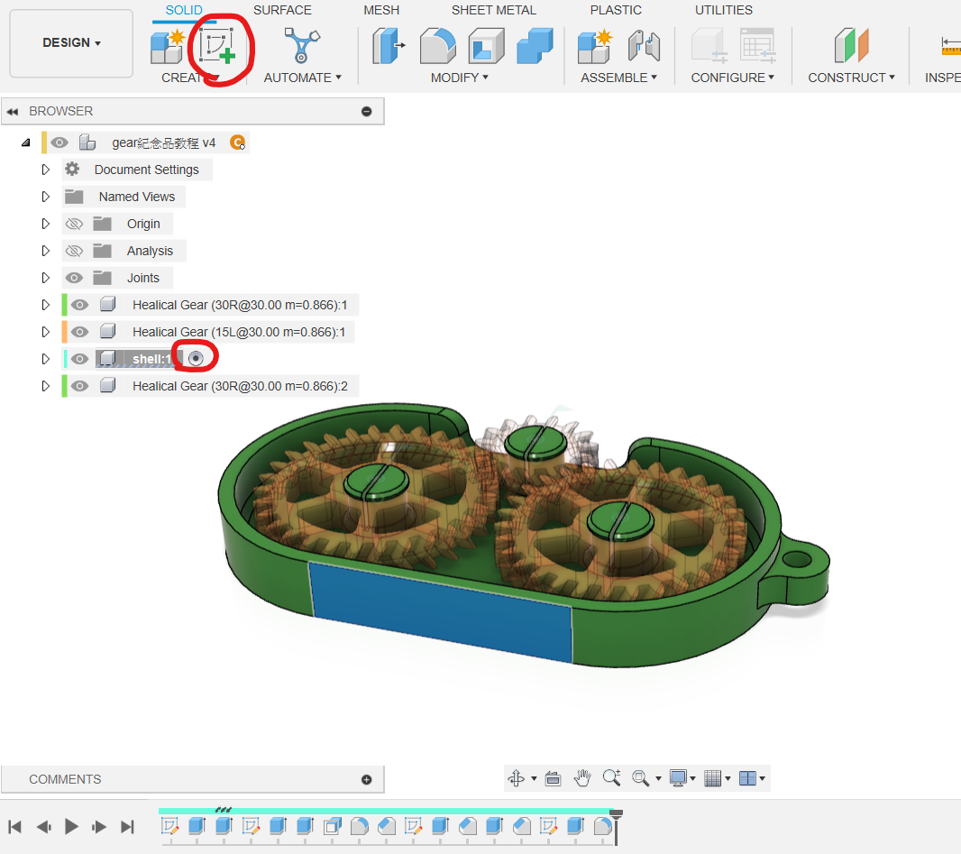
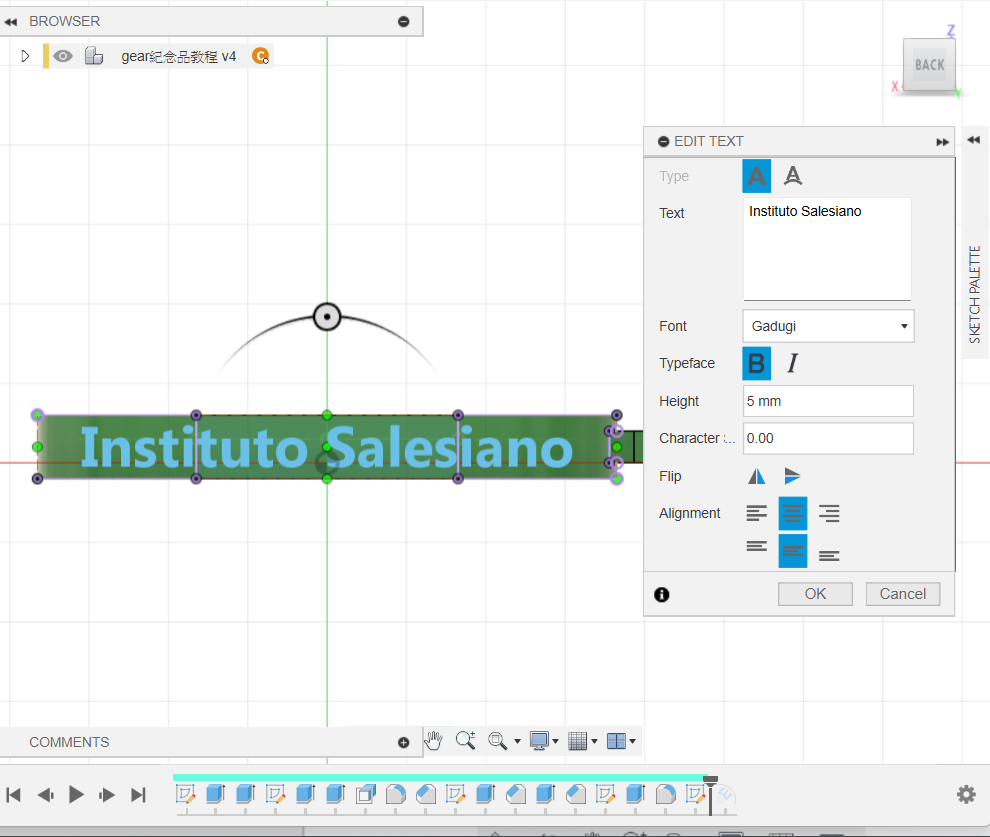
Activate Shell and sketch on its flat face. Add 5 mm-high text. Project the rear curved face to align the text box with the origin. Choose a bold, simple font suitable for printing.
ℹ️INFO
Not every font supports solid operations; many CJK fonts cannot be extruded or embossed successfully.
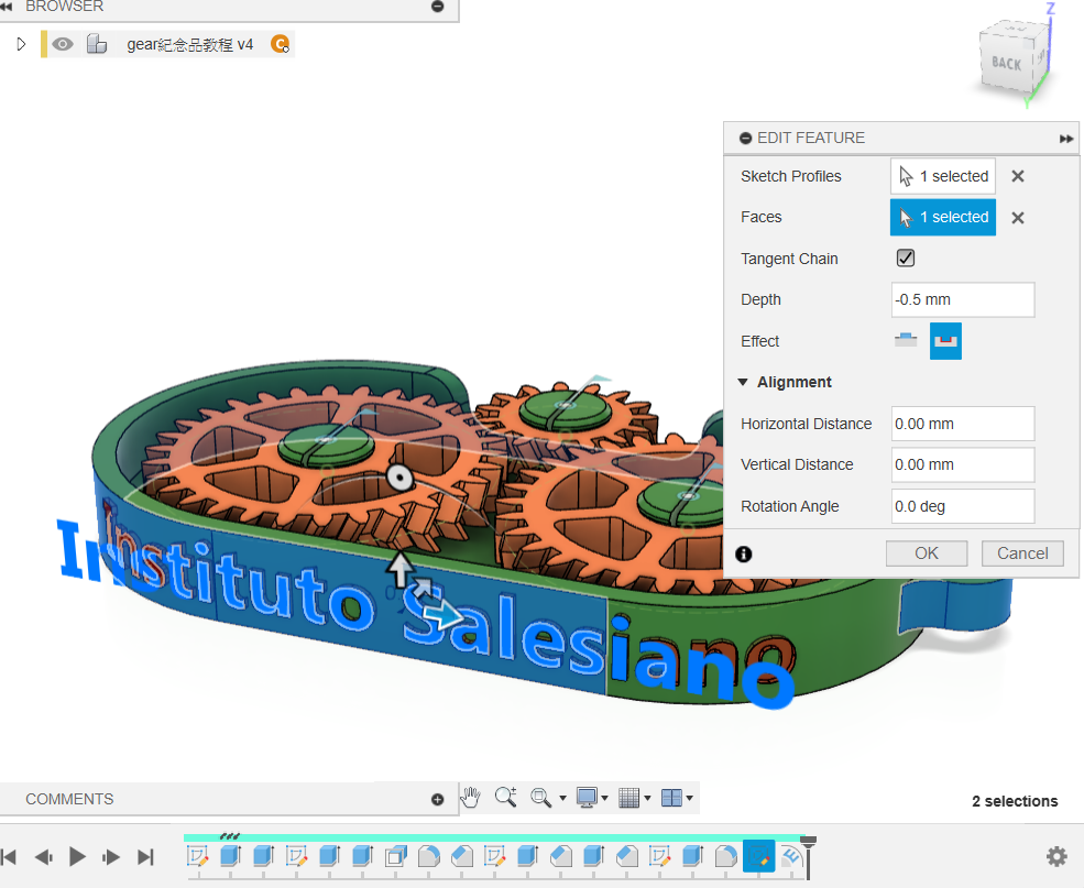
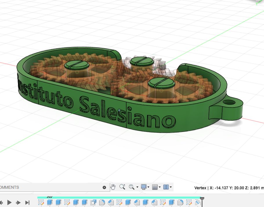
Search for Emboss. Select the whole text object under Sketch Profiles and the curved housing face under Faces. Choose raised or recessed text. A depth of 0.5 mm should normally print without additional support in either direction.
6. Key Points
📝NOTE
- Helical and herringbone gears carry loads smoothly; a herringbone pair cancels axial thrust and self-centres, reducing the need for separate retaining hardware.
- Printed gears require backlash.
Offset Facemakes the clearance easy to tune after generation. - Revolute joints can be coupled with
Motion Linkto simulate the actual gear ratio and direction.
Translation notice: This English page was generated automatically by AI and has not yet been reviewed by a human. It will be checked and revised page by page when time permits.