Walking Linkage Robot
ℹ️INFO
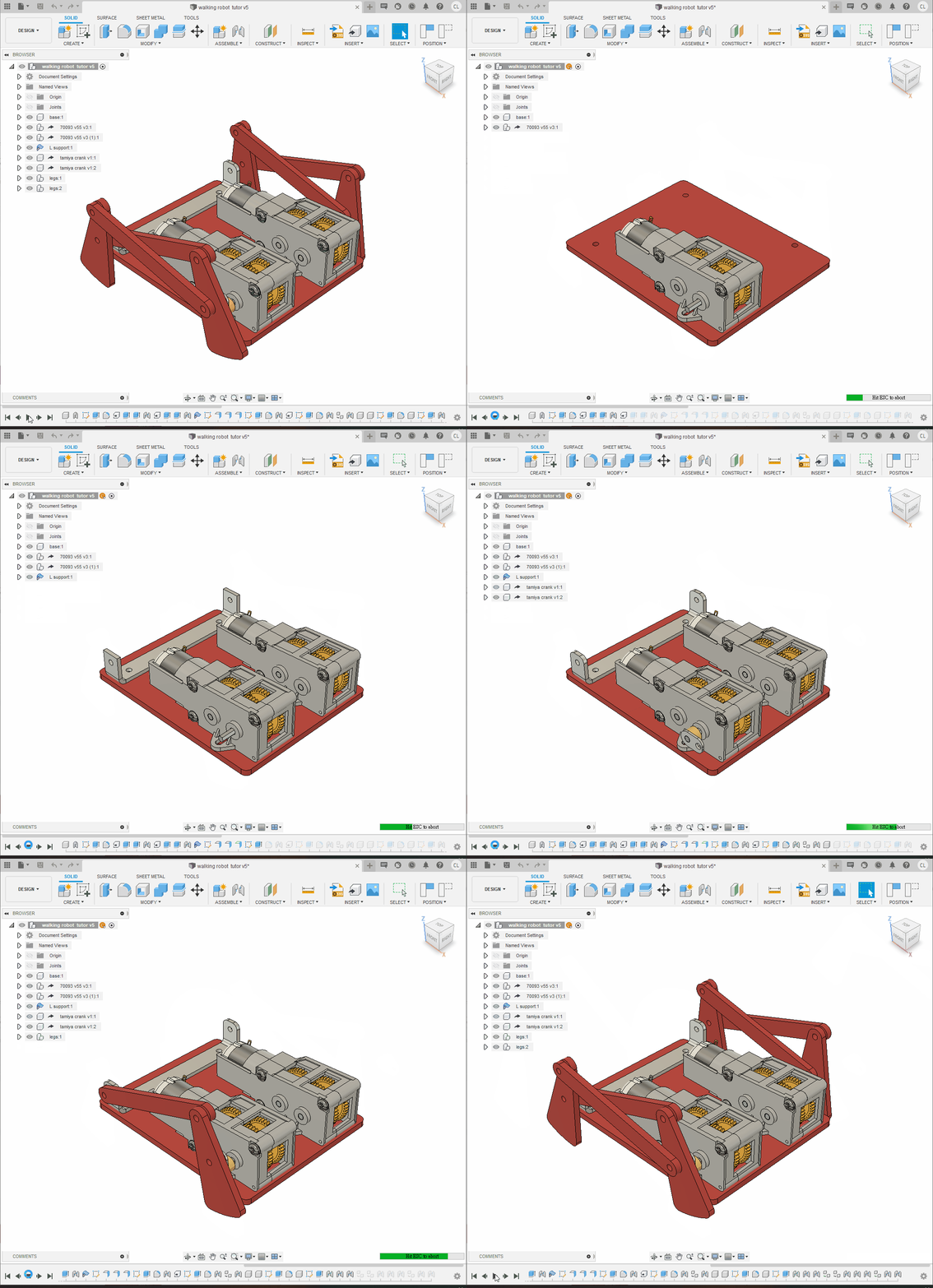
This chapter models the four-legged linkage robot shown below. Its main purpose is to practise Fusion 360 joints and combine different joint types to simulate a real mechanism.
Files
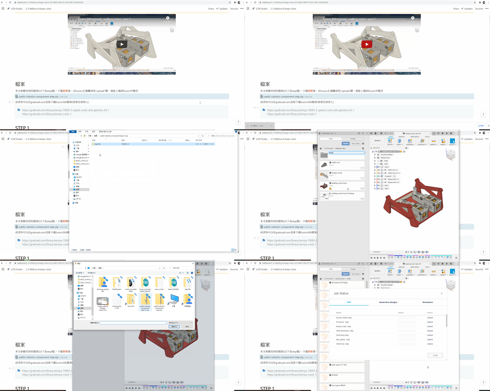
The 70093L and 70093R models may already be uploaded from an earlier exercise. Otherwise, download and extract the STEP archive, then use Upload in Fusion's Data Panel.
Alternative Fusion models are available from GrabCAD (account required):
Upload demonstration
Step 1: Base
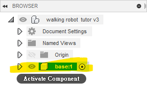
Create and activate a component named base.
⚠️WARNING
Confirm that the activation dot appears beside base before adding its features.
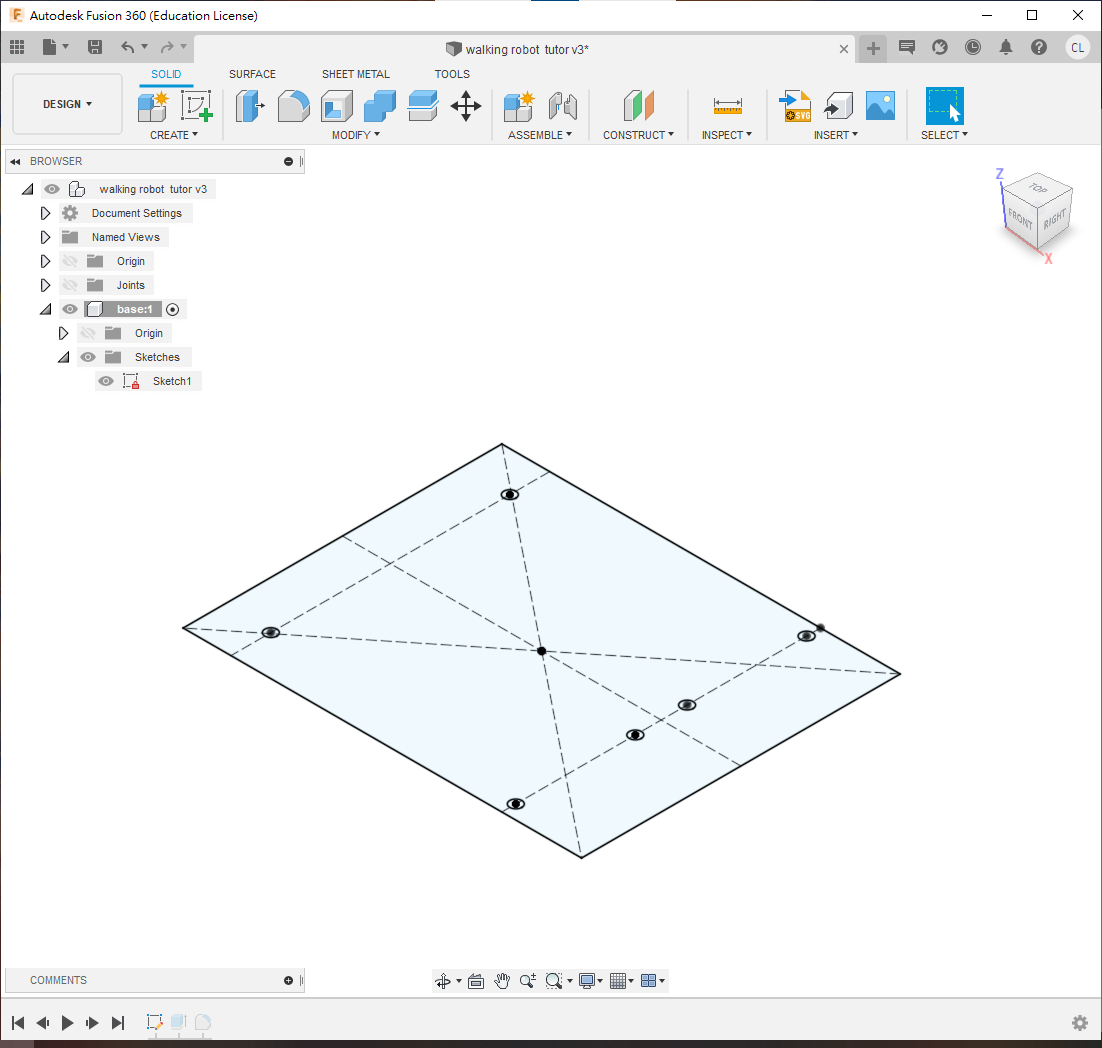
Sketch the base on the XY plane to the dimensions shown.
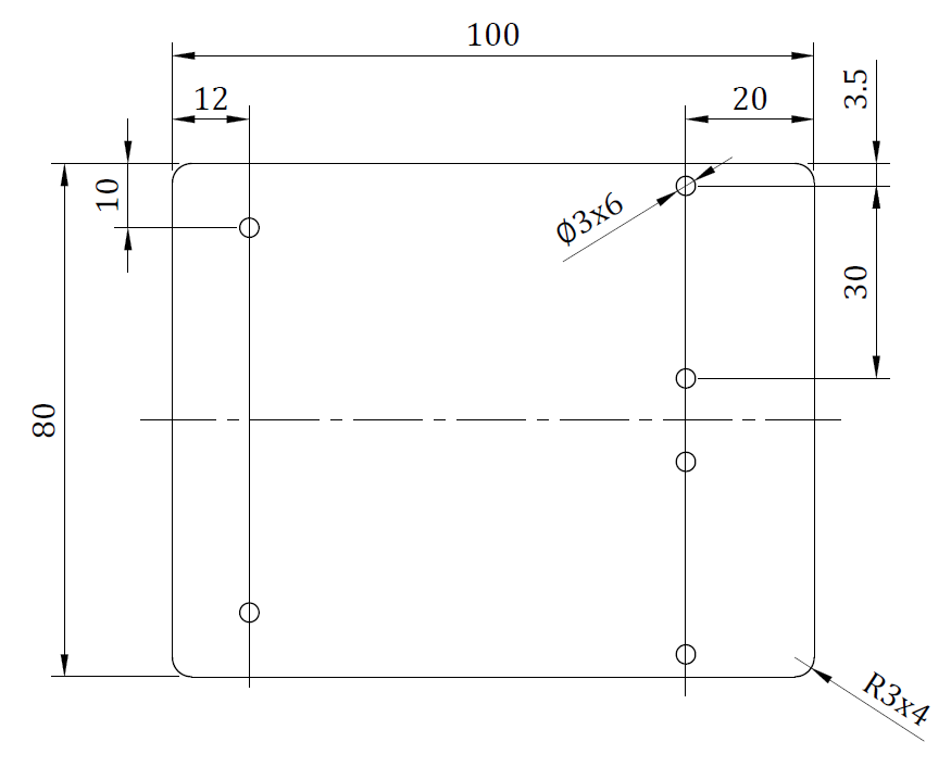
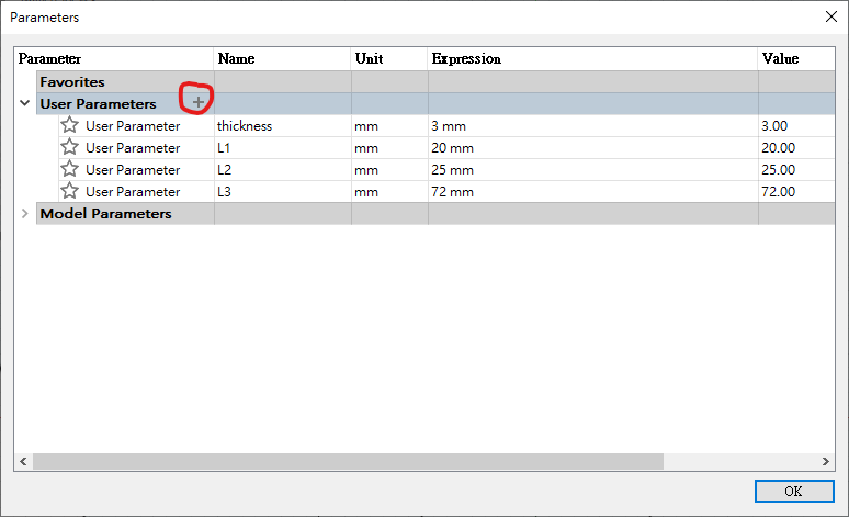
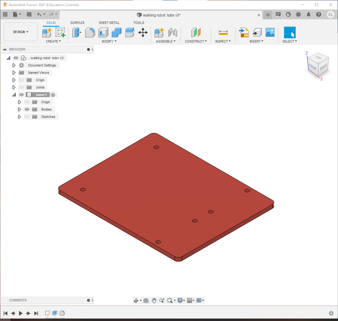
Open Change Parameters, create thickness = 3 mm, and extrude the base by thickness.
Step 2: Gearboxes
Search for Insert Derive and derive the 70093L gearbox. Select its component, right-click and choose Rigid Group.
⚠️WARNING
Use Insert Derive rather than dragging the gearbox into the design; a directly inserted reference cannot be modified in the required way.
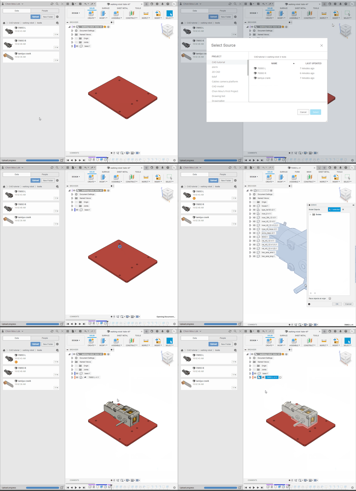
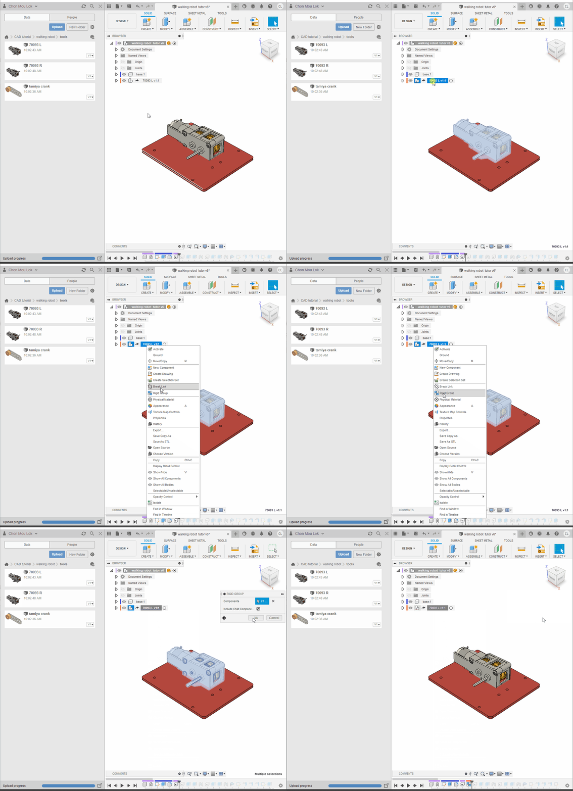
Activate the gearbox, press E and shorten or extend the output shaft as required. Return to the top level and press J to joint the gearbox to the base.
💡TIP
When choosing a joint origin, hover over the intended face and hold Ctrl to lock that face while selecting its point.
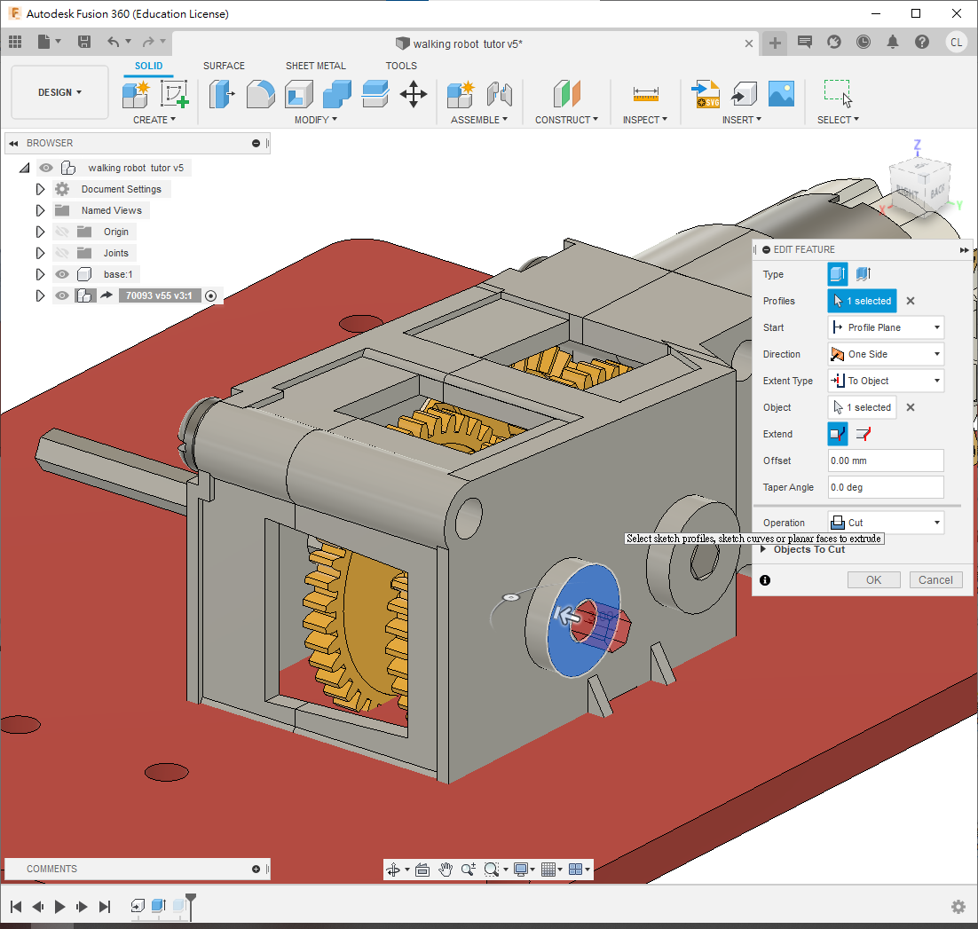
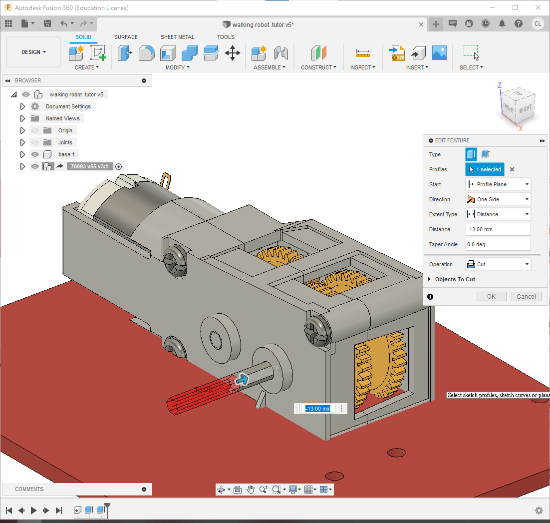
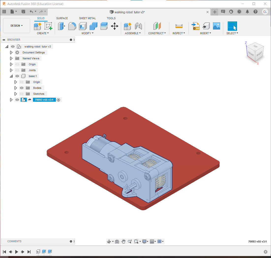
Derive the second 70093 gearbox separately, activate it, adjust its shaft and joint it to the base.
⚠️WARNING
Do not copy and paste the first derived gearbox. Separate derived components can be modified independently; copied occurrences would update together.
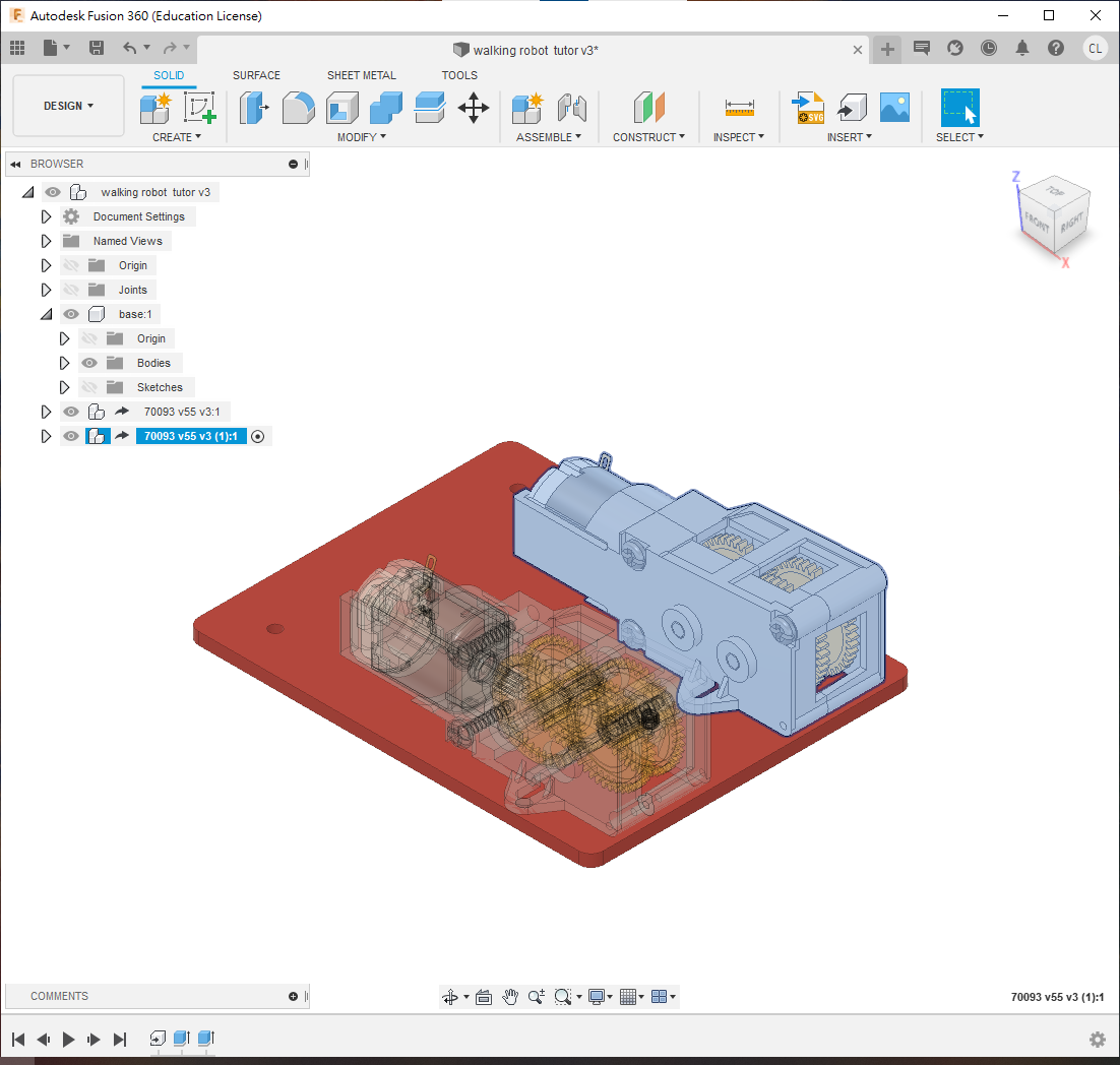
Step 3: Sheet-Metal Support
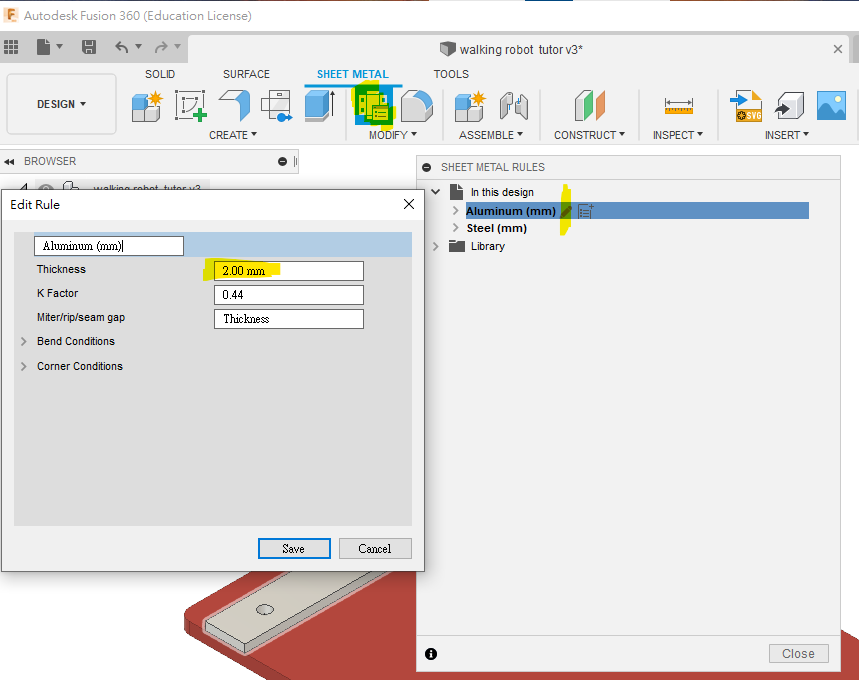
Reactivate the top level and create a Sheet Metal component named L support. Choose the required material and thickness; its icon differs from a standard component.
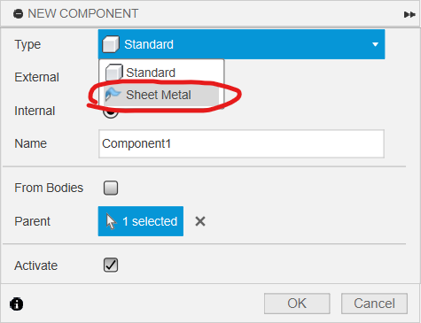
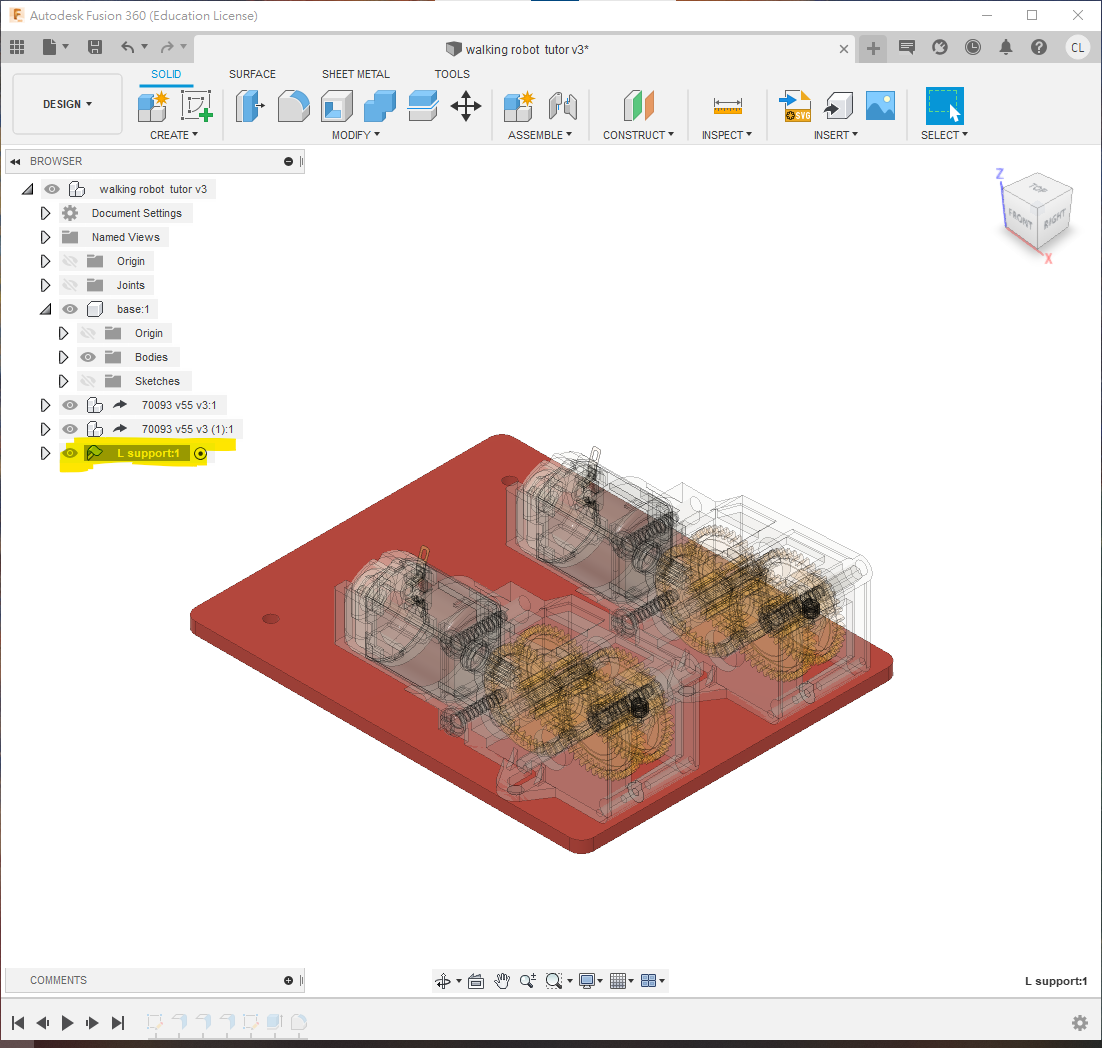
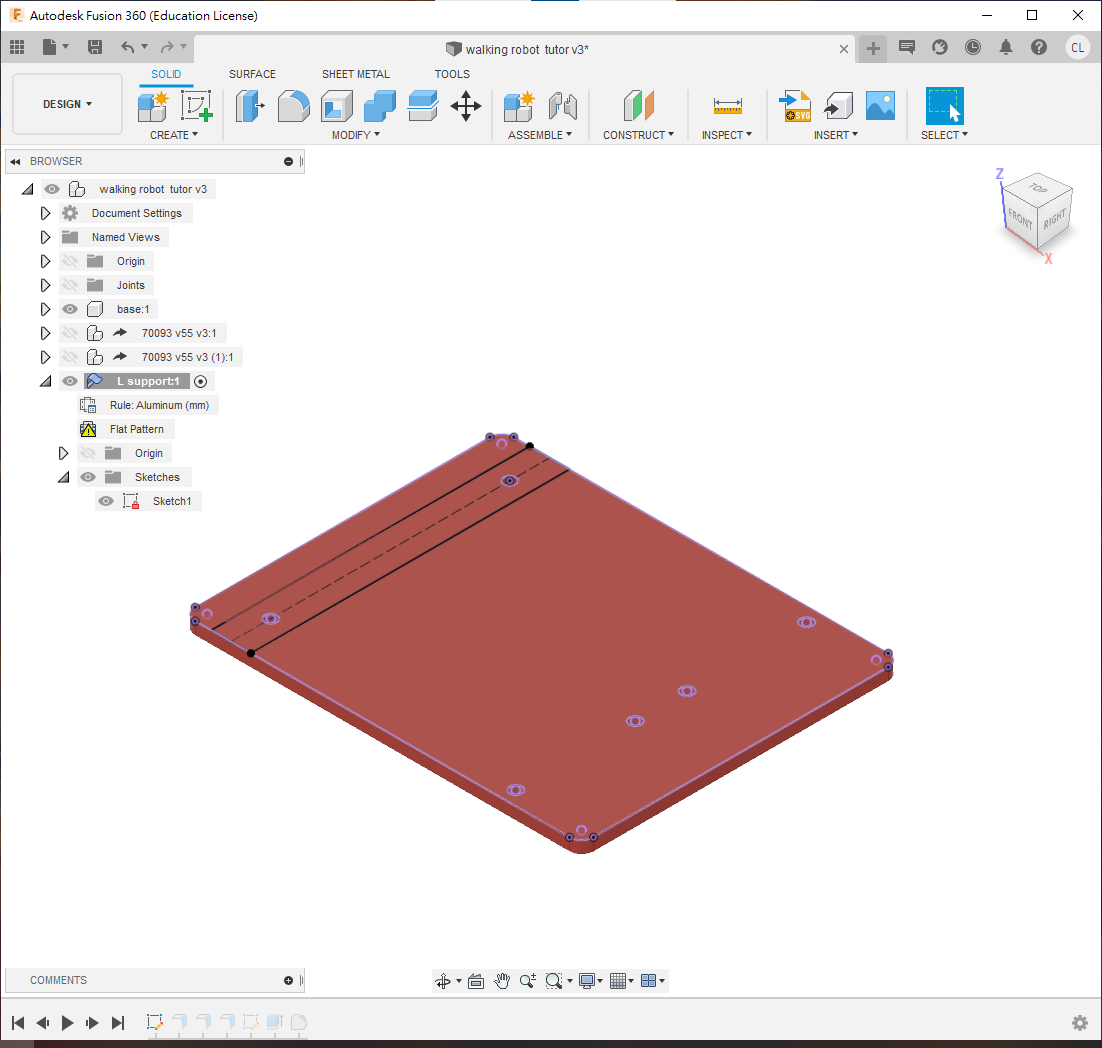
With L support active, sketch on top of the base. Draw a centreline through the hole centres and a 10 mm-wide rectangle, using Midpoint or Symmetry to centre it.
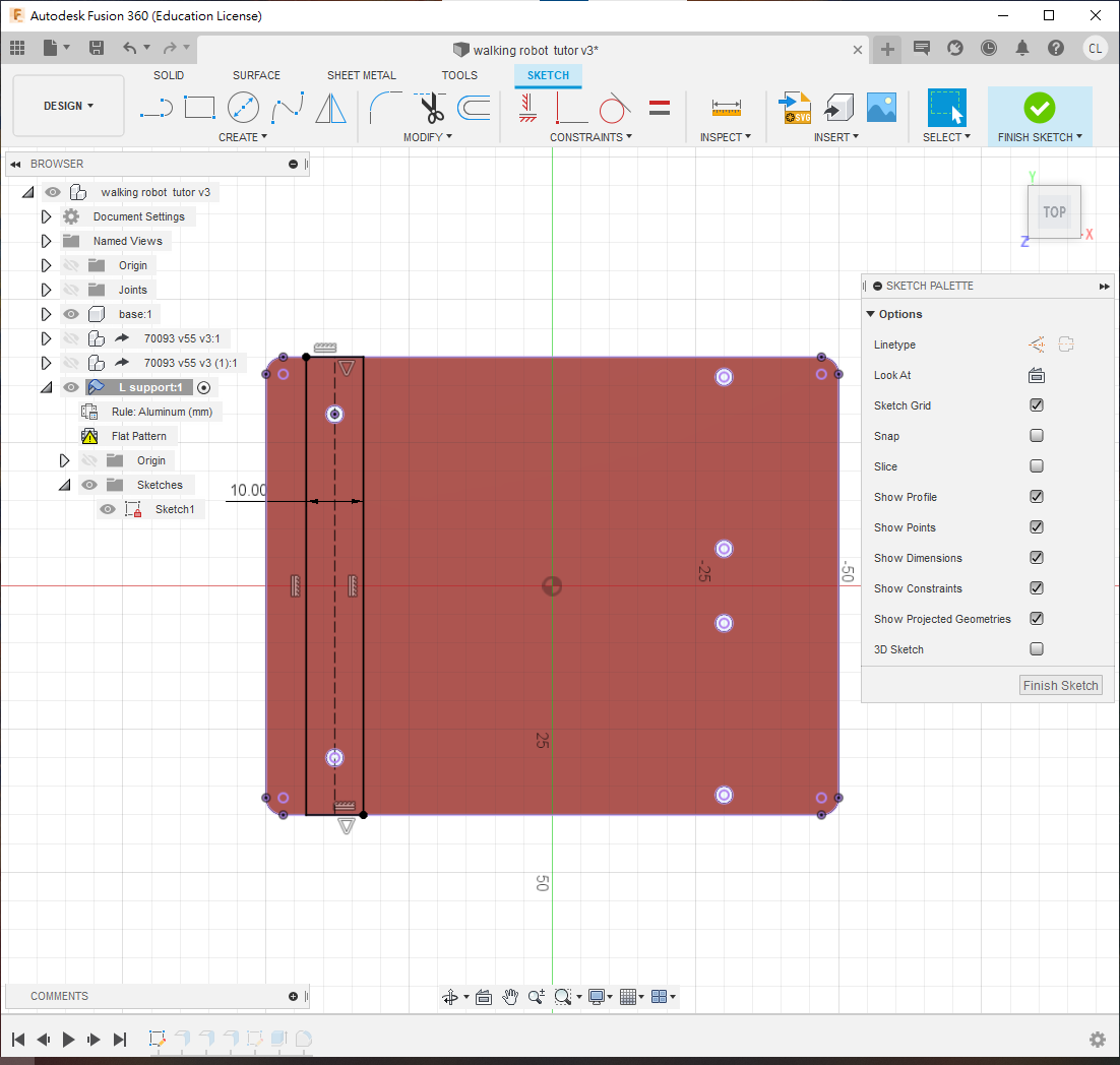
In the Sheet Metal workspace, use Edit Rule if the material properties need adjustment. Use Flange—not Extrude—to turn the rectangle into a 2 mm sheet-metal base.
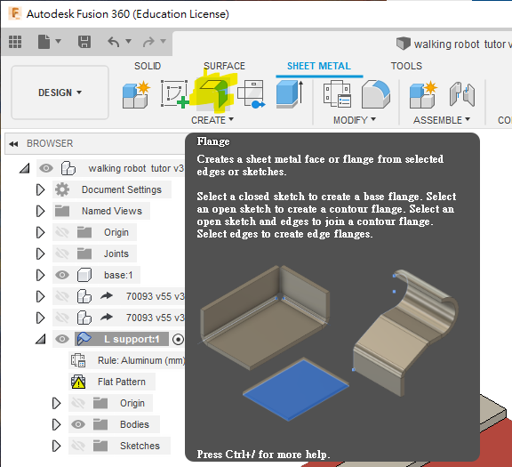
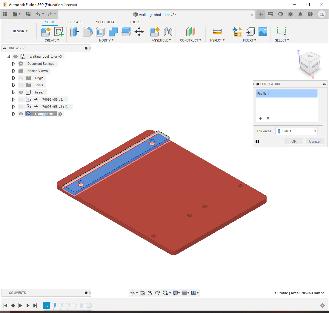
Use Flange on each long edge. Set Height Datum to 16 mm and Bend Position to Inside.
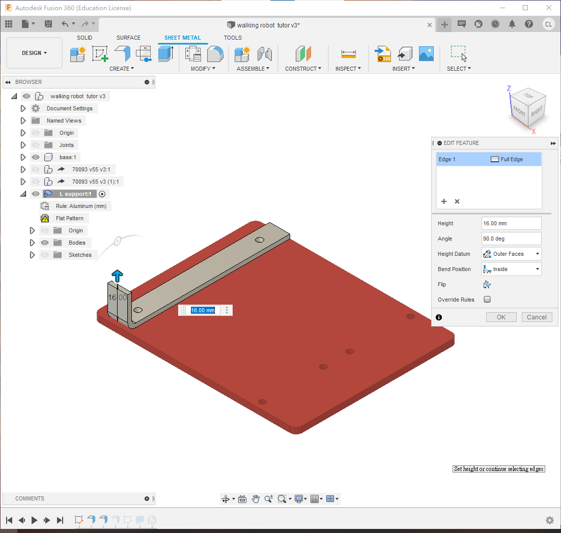
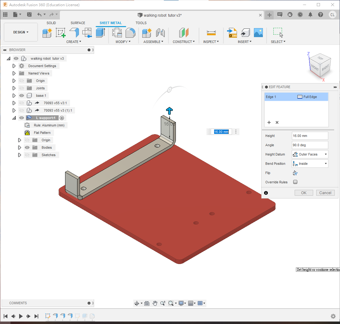
Sketch on a raised face. Show one gearbox and press P to project its output-shaft circle so the support hole is at the same height. Add a centreline and a Ø3 mm circle, aligning it horizontally/vertically to the shaft centre.
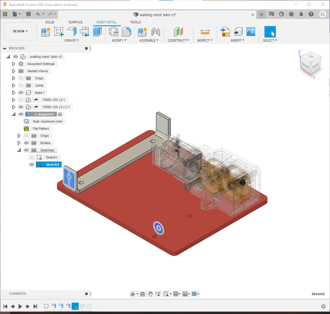
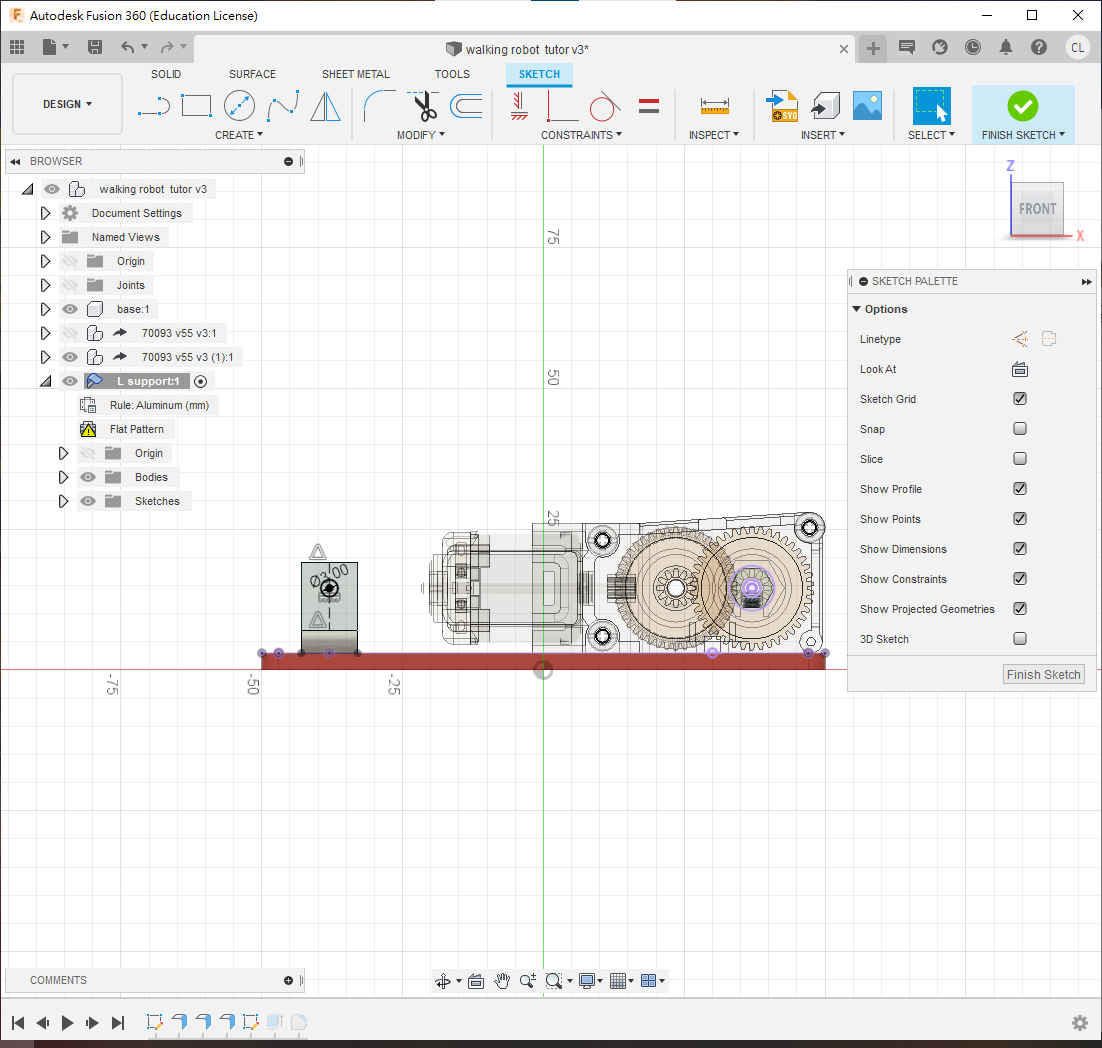
Cut the circle To Object through the opposite side, then apply 3 mm corner fillets.
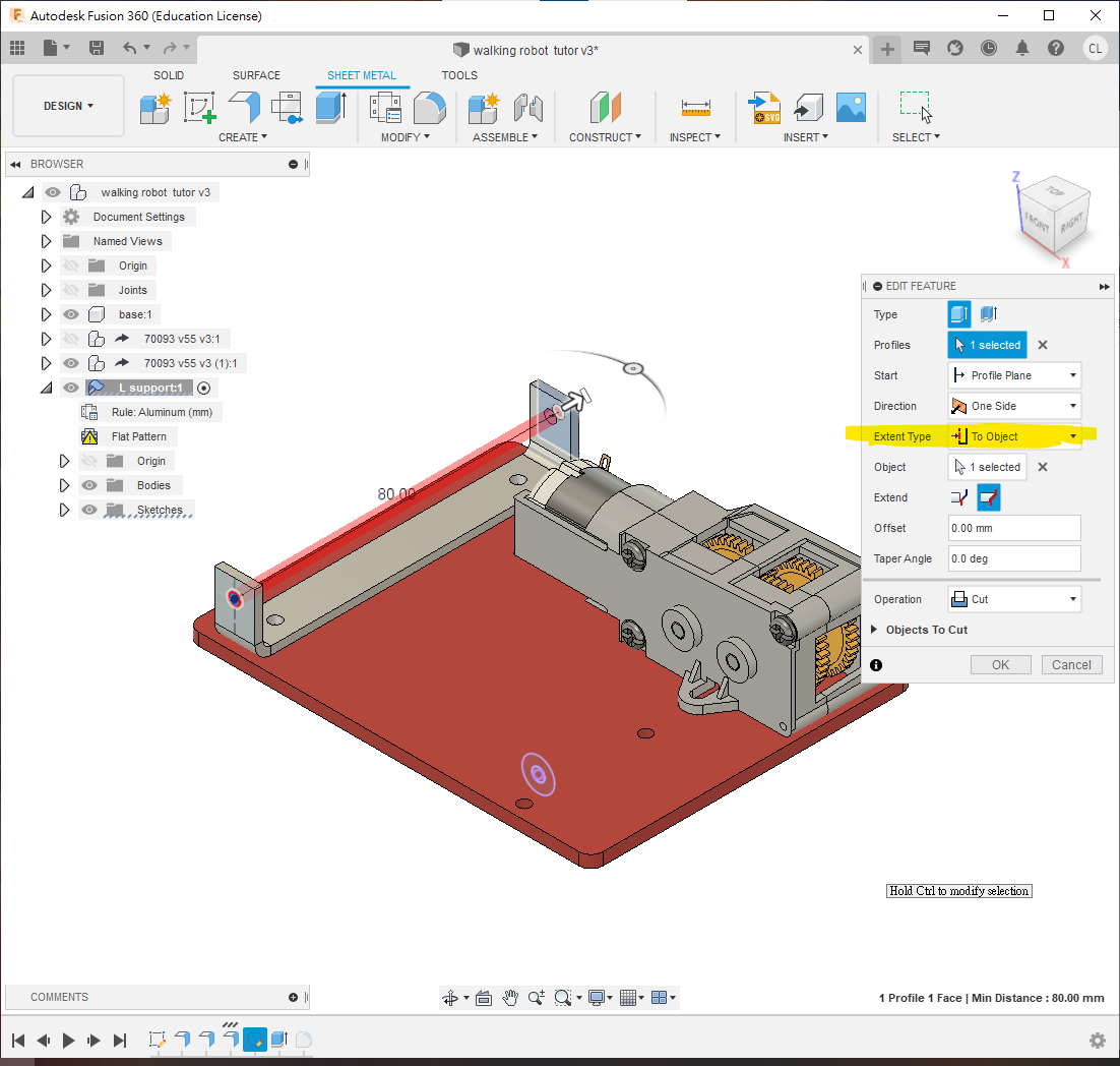
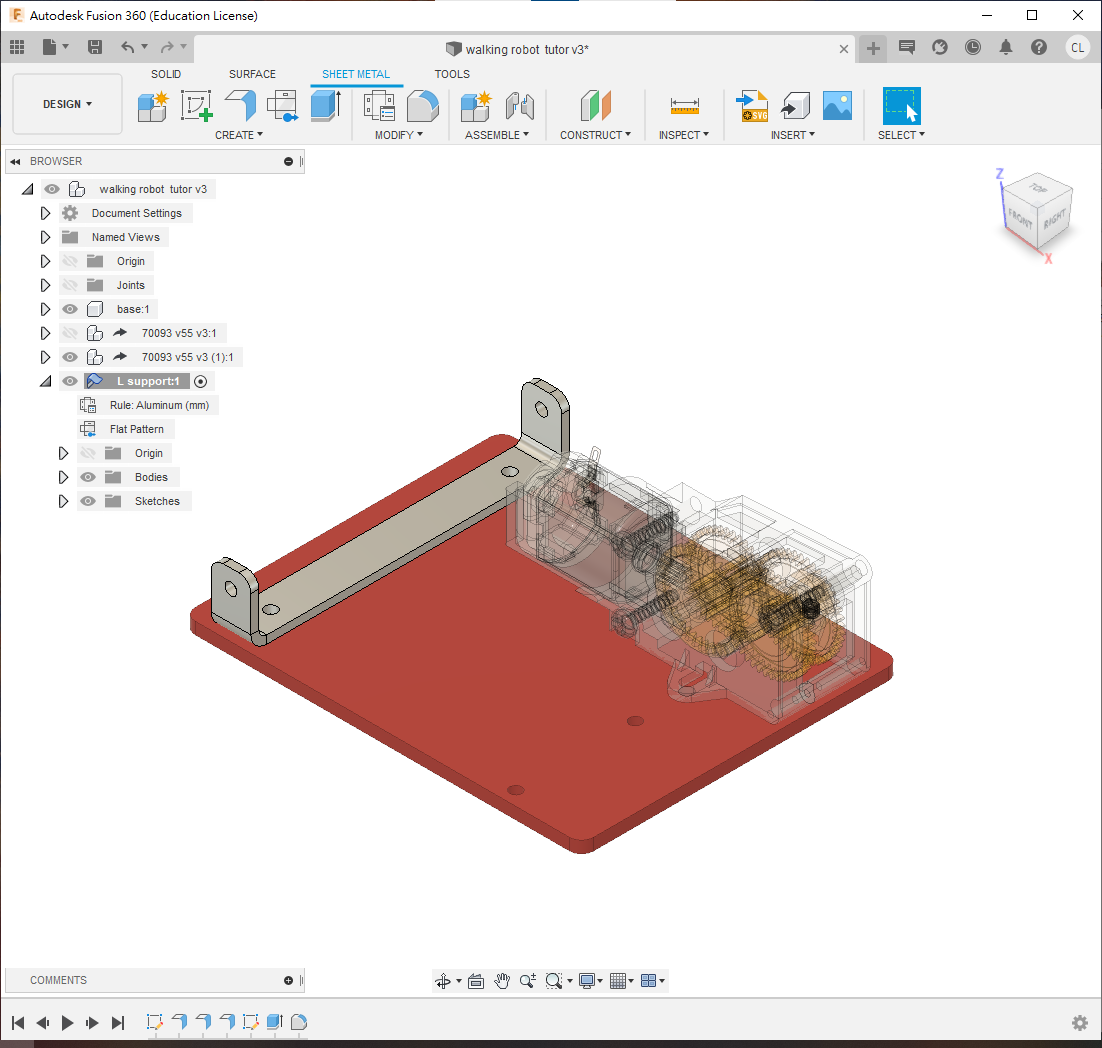
Reactivate the top level and joint the support to the base.
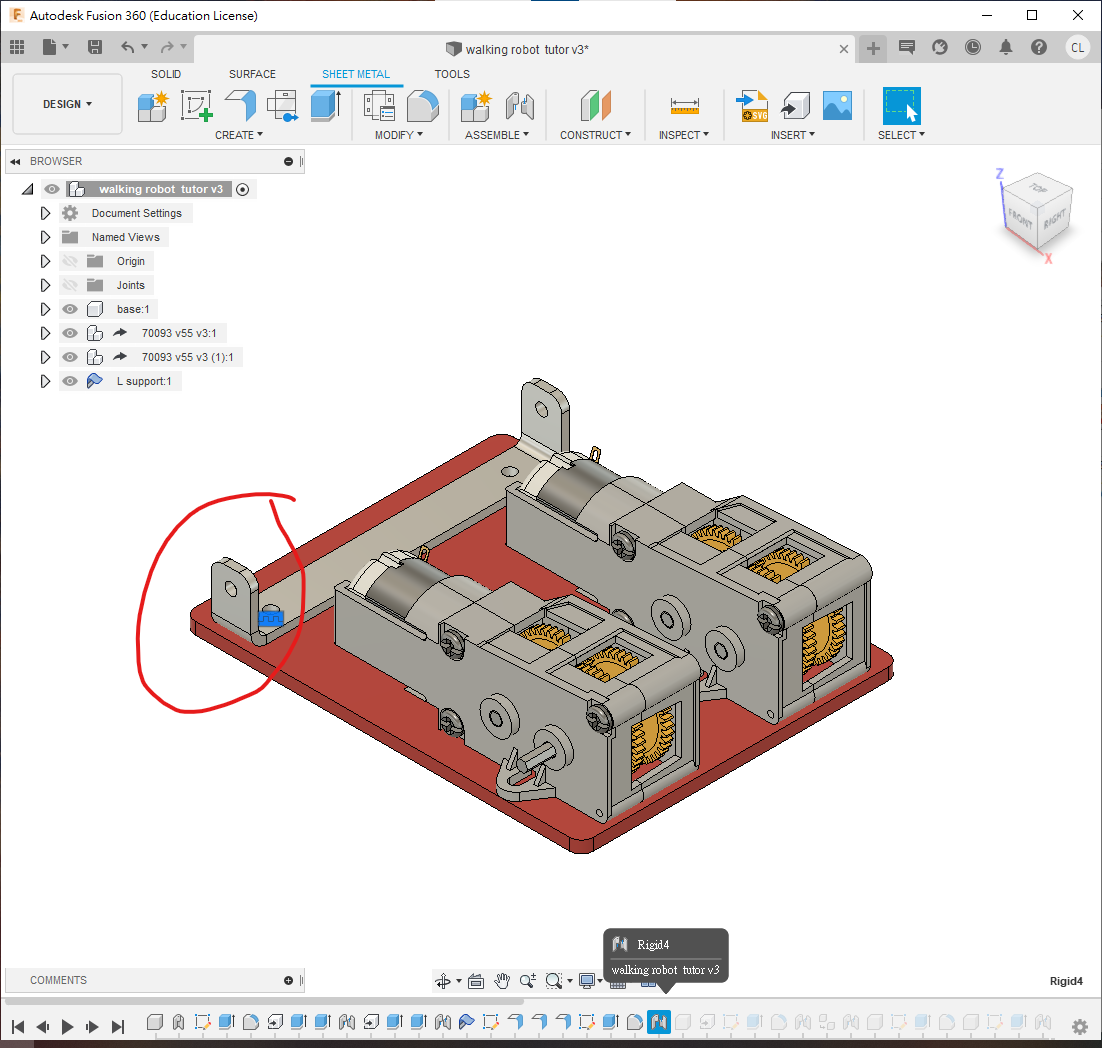
Step 4: First Crank
At the top level, derive the Tamiya crank. Activate it, sketch on its face, project the geometry and draw the cut line shown.
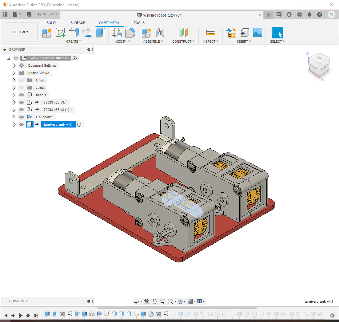
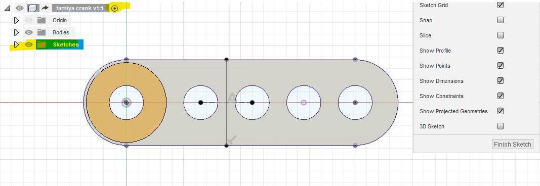
Cut away the excess, leaving the nearest hole. Return to the top level and joint the crank to the gearbox shaft.
ℹ️INFO
If using the Fusion model whose internal gearbox shaft already rotates, use a Rigid joint between crank and shaft. If using a static STEP gearbox, use a Revolute joint to provide that rotation.
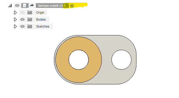
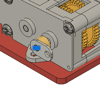
Step 5: Second Crank
At the top level, copy and paste the crank and joint it to the other gearbox shaft. Orient it 180° opposite the first: if the left crank points backwards, the right points forwards.
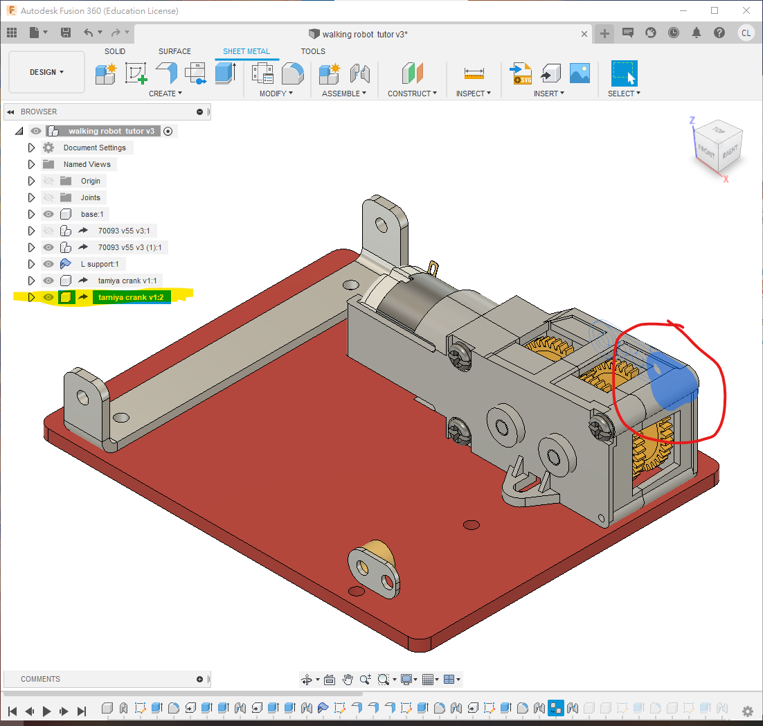
Step 6: Leg Assembly Structure
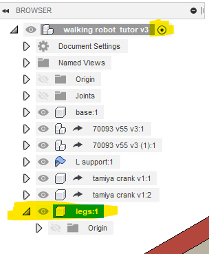
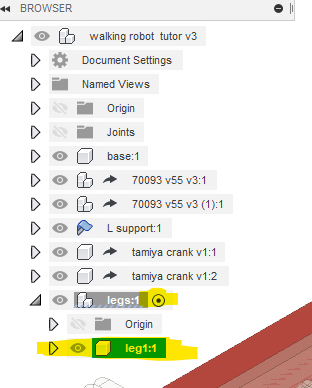
Create a top-level component named legs to contain every left-side leg and linkage. Activate it and create a child component named leg1.
⚠️WARNING
All legs and linkages that must be copied together need to remain beneath legs; otherwise their internal joint relationships will not travel with the copy.
Step 7: First Leg
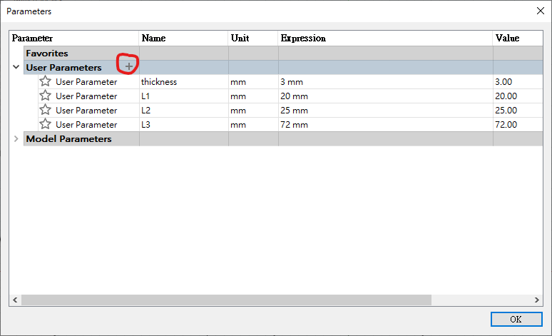
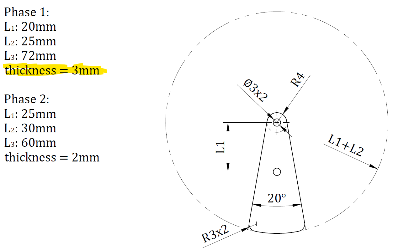
Activate leg1, hide all other components and sketch on the origin XZ plane to the dimensions shown. Define repeated linkage dimensions as user parameters so later changes update every dependent feature.
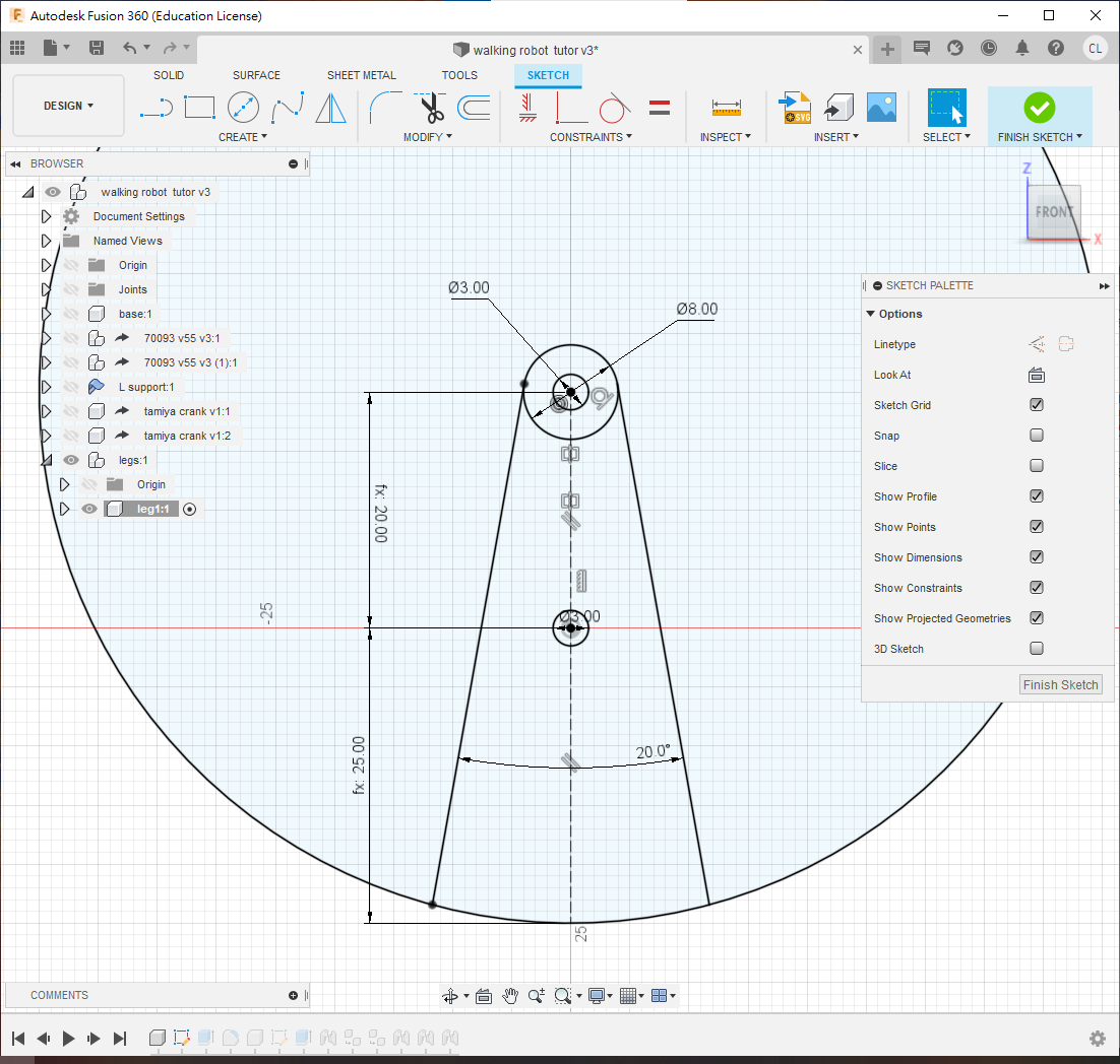
Extrude by thickness and apply approximately 3 mm fillets.
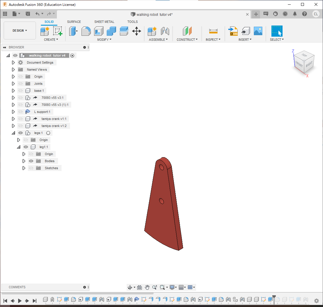
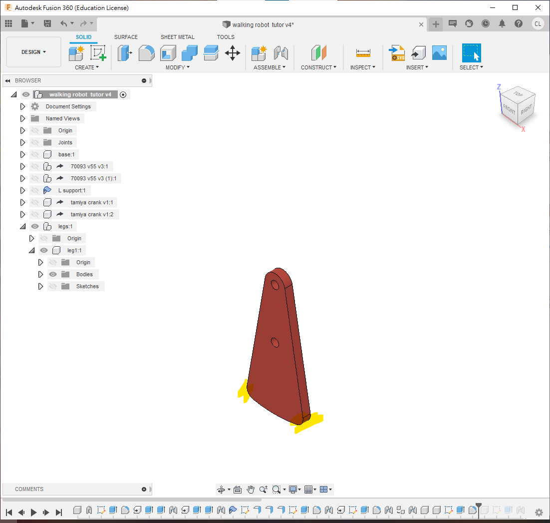
Step 8: First Linkage
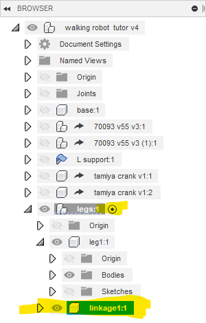
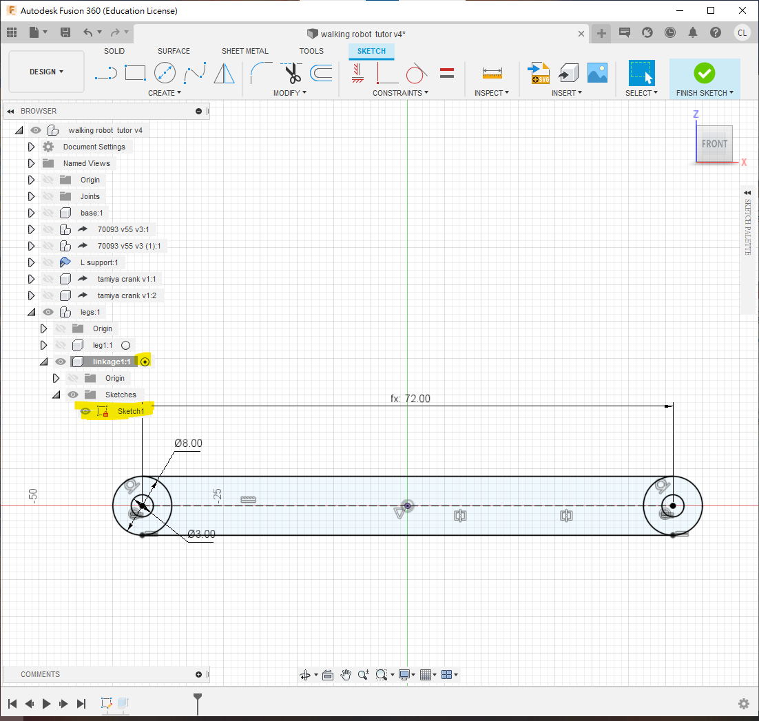
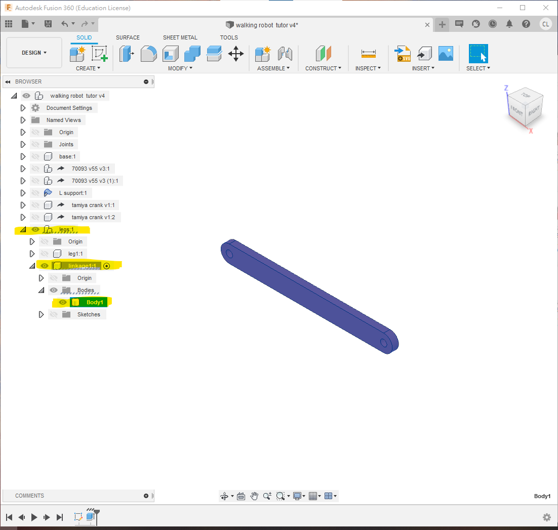
Activate legs, create a child component named linkage1, hide all others and sketch on XZ. Set L3 = 72 mm if it was not already defined, then extrude by thickness.
Step 9: Linkage to Support
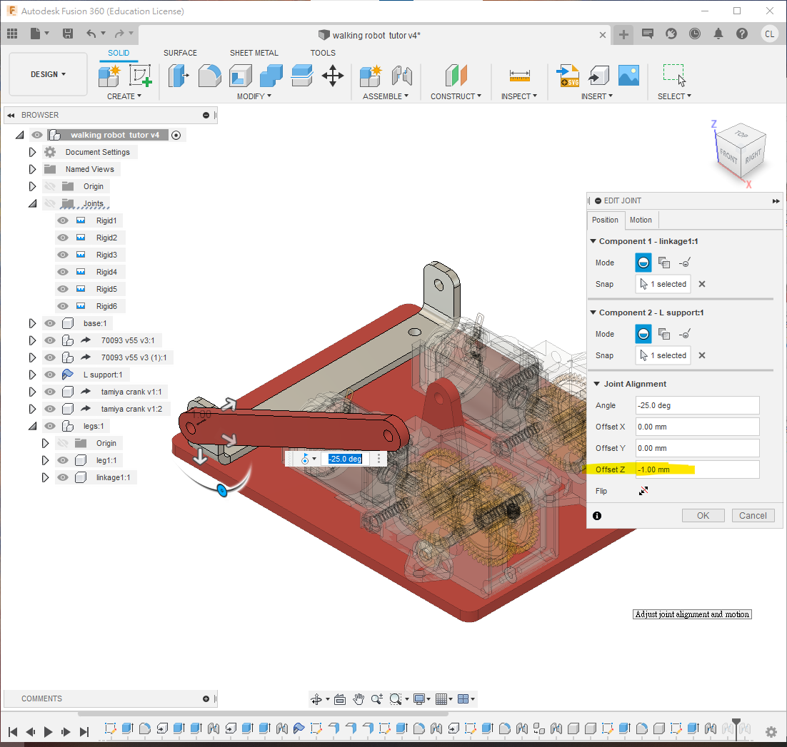
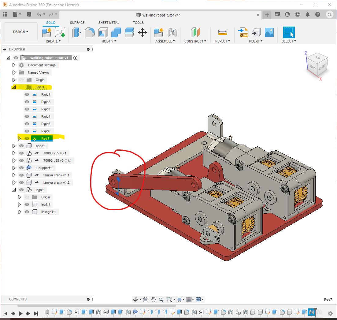
Show all parts. Press J and connect linkage1 to the aluminium support with a Revolute joint, leaving 1 mm between faces for a real spacer and starting at about 25°.
Because the support lies outside legs, this joint is created at the design's top level rather than inside legs; it will not be included when legs is copied.
Step 10: Leg to Crank
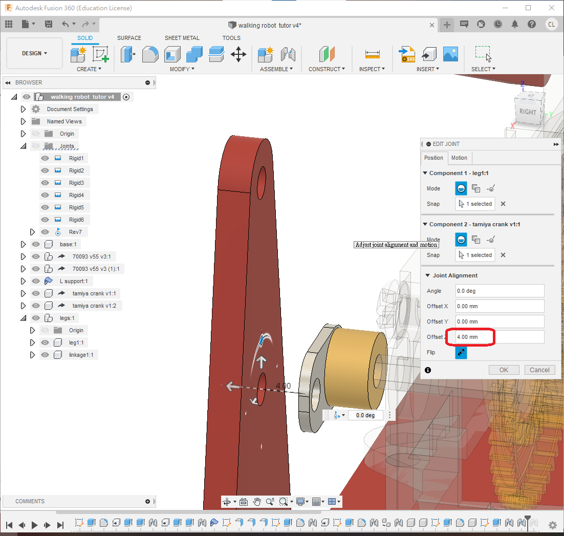
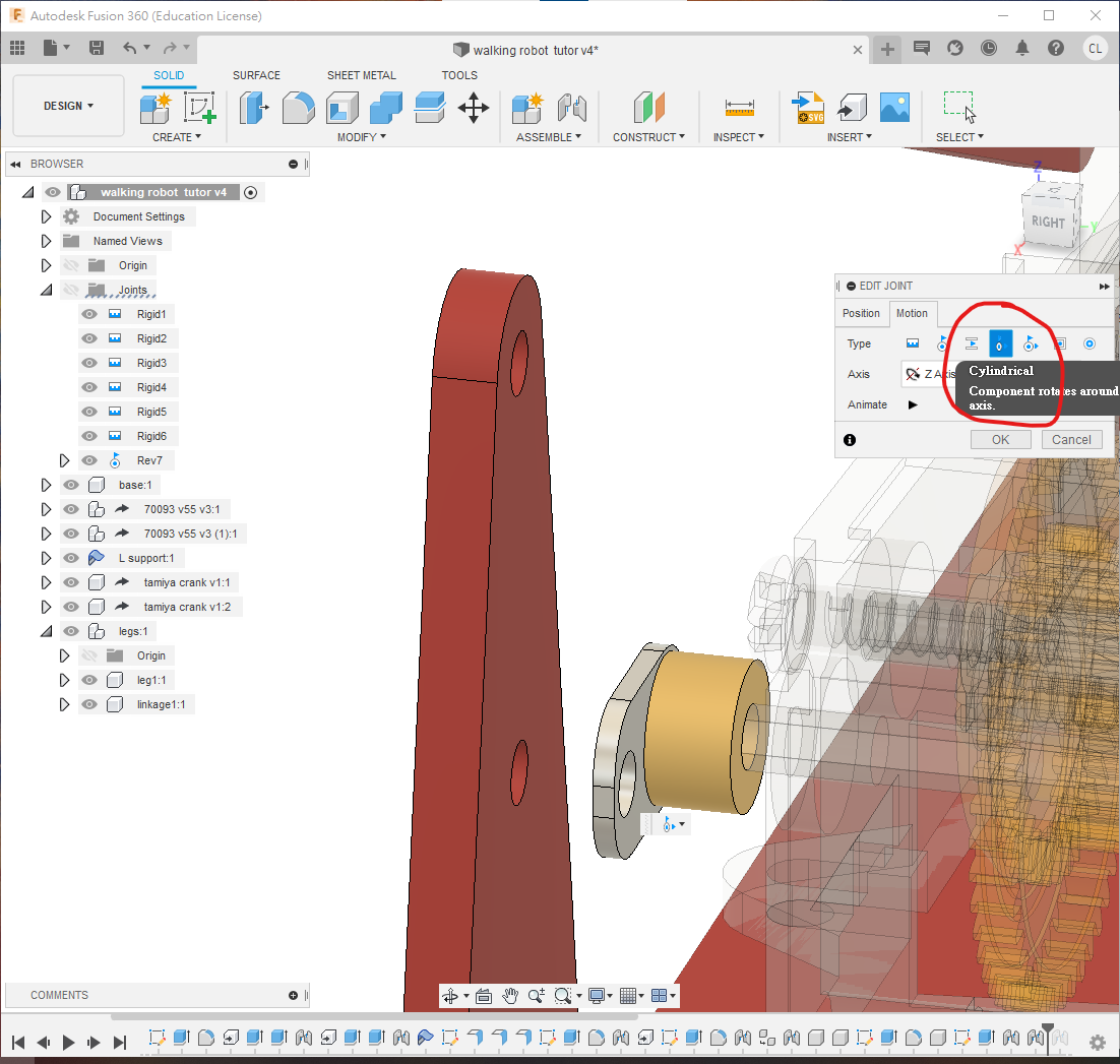
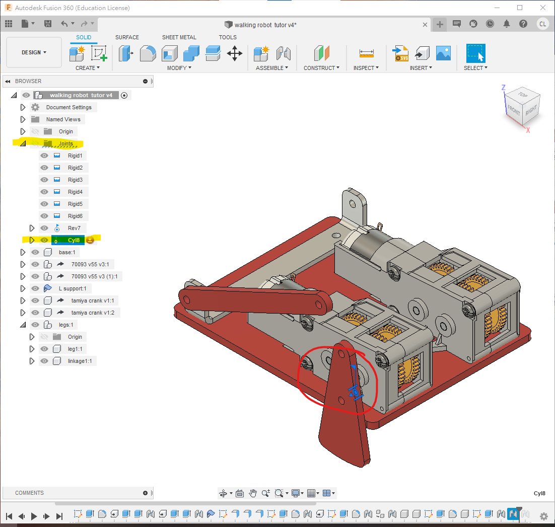
Joint leg1 to the crank with an initial 4 mm offset and choose Cylindrical motion. A Cylindrical joint allows both rotation and sliding along its axis, so the initial axial offset is not a fixed constraint.
Revolute vs Cylindrical
| Property | Revolute | Cylindrical |
|---|---|---|
| Rotation | Yes | Yes |
| Axial sliding | No | Yes |
| Degrees of freedom | 1 | 2 |
| Typical use | Rotation at a fixed axial position | Rotation plus axial self-alignment |
Step 11: Close the First Four-Bar
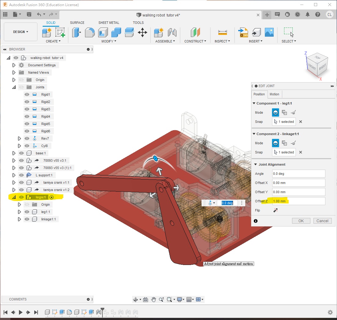
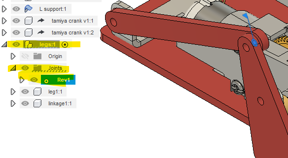
With legs active, joint leg1 to linkage1 with a 1 mm face gap and Revolute motion. Confirm that this joint appears beneath legs so it will be copied with the subassembly.
💡TIP
A robust way to assemble this four-bar model is to use two Revolute joints and one Cylindrical joint among its three moving connections. The Cylindrical joint absorbs the axial spacing, avoiding an over-constrained model.
Step 12: Duplicate Leg and Linkage
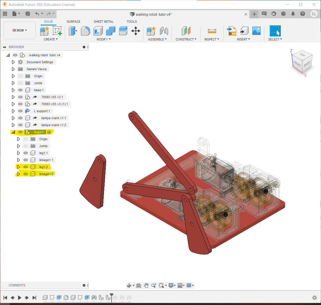
Keep legs active and copy/paste leg1 and linkage1, creating second occurrences beneath the same parent.
Step 13: Complete the Left Linkage
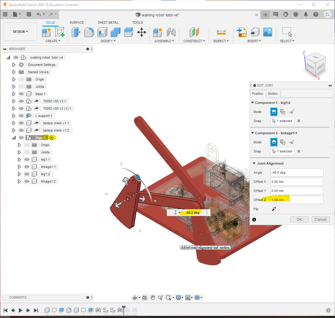
- Joint
leg1:2to the first linkage with a1 mmoffset and Revolute motion. - Joint
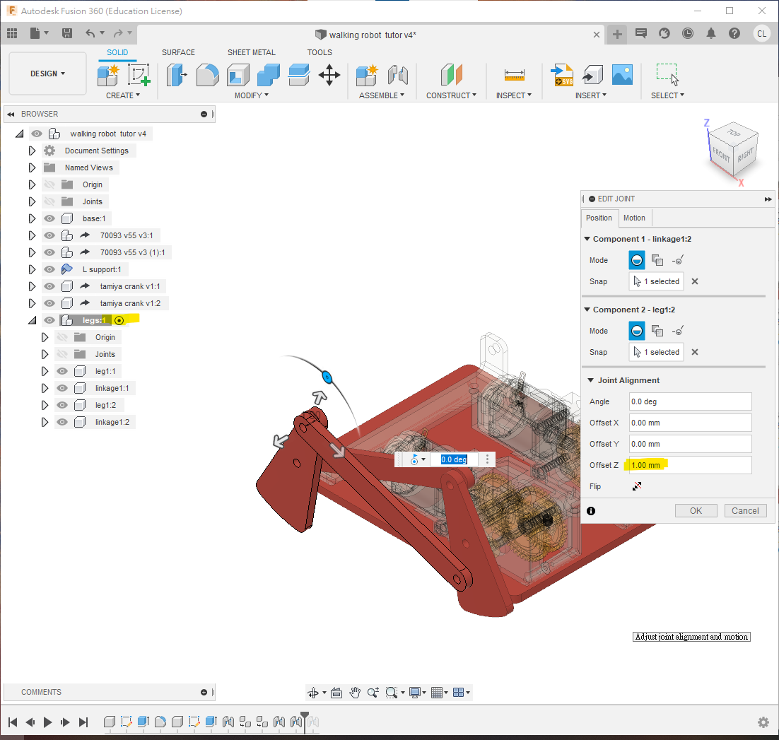
linkage1:2toleg1:2with a1 mmoffset and Revolute motion. - Joint the other end of
linkage1:2toleg1with Cylindrical motion and no fixed offset.
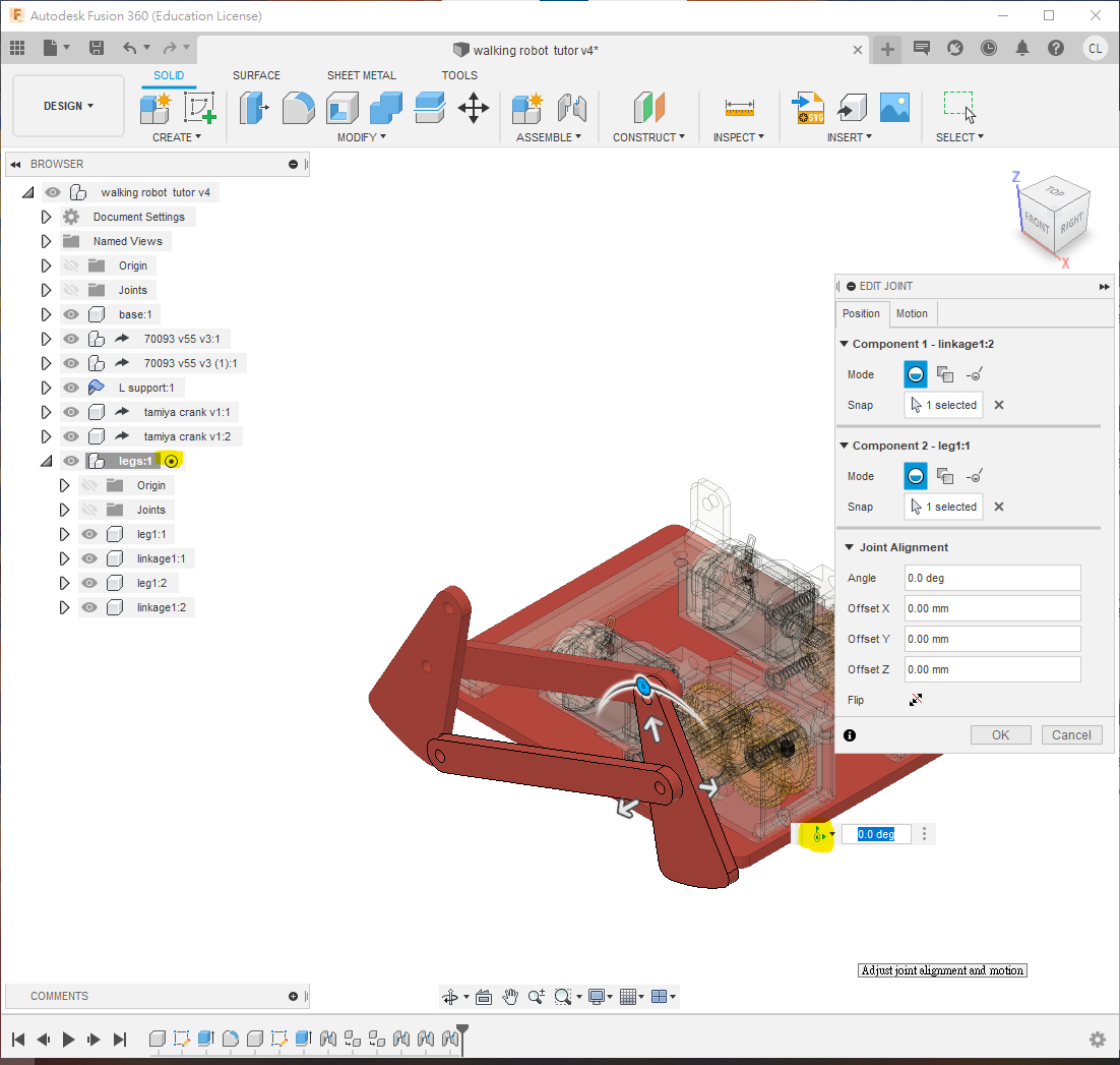
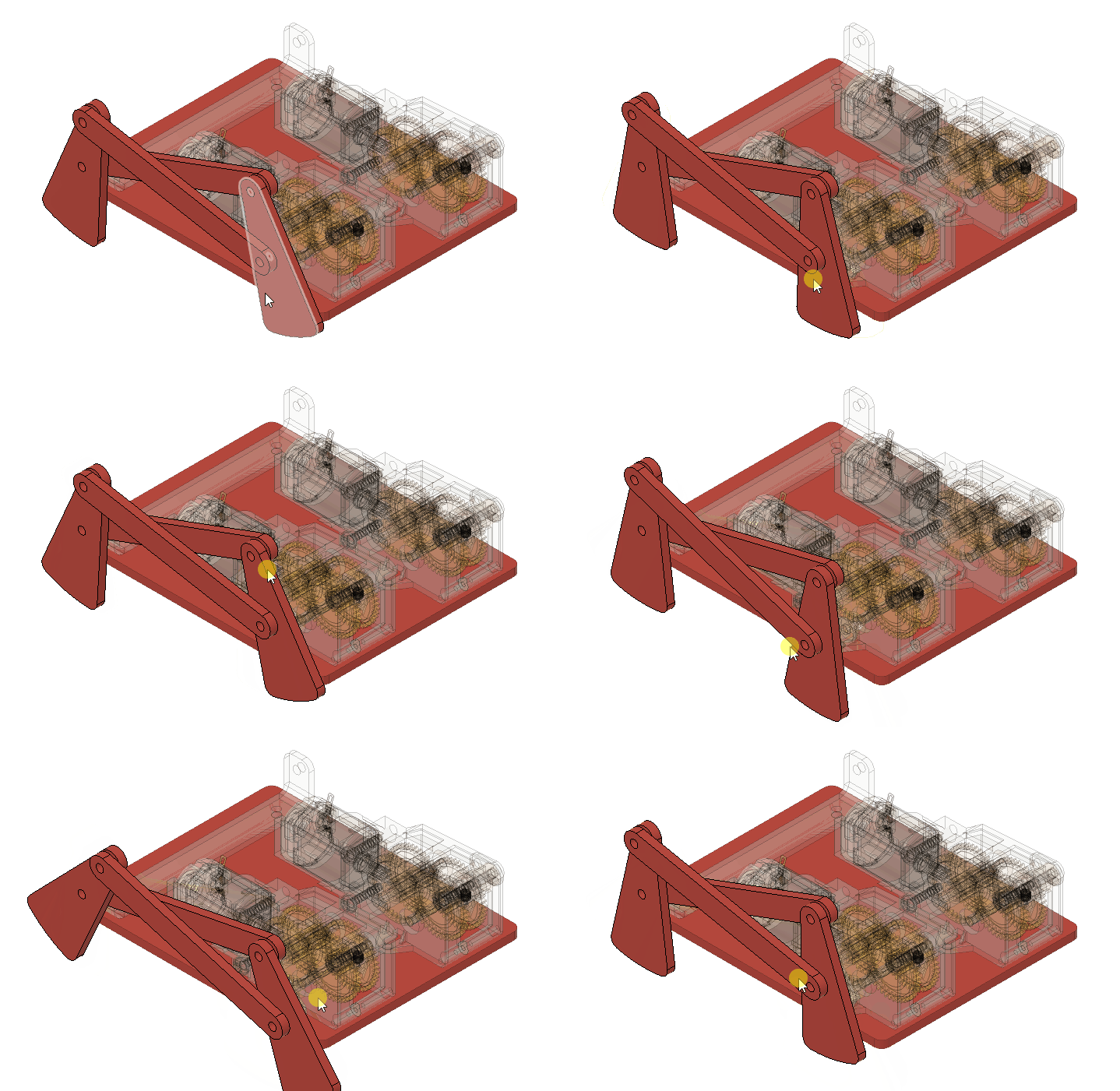
Step 14: Test the Left Side
Rotate the gearbox and confirm that the legs follow. Change the leg/linkage gap from 1 mm to 0.5 mm or another value; a properly constrained parametric model should update without timeline errors.
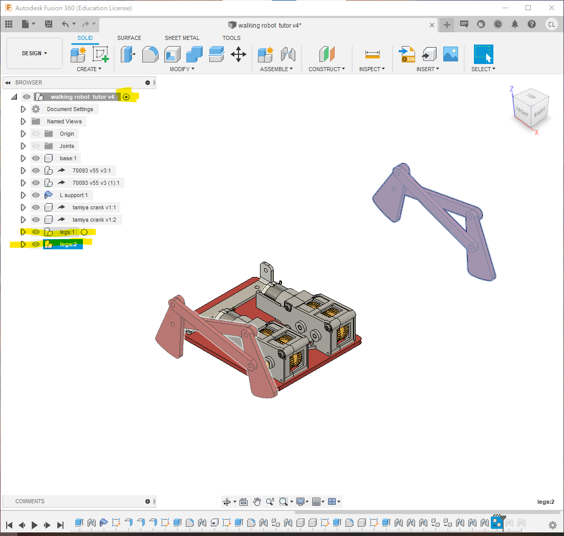
Step 15: Duplicate the Leg Assembly
Reactivate the top level and copy/paste the entire legs component to create the right-side subassembly. Move the copy aside temporarily.
ℹ️INFO
Fusion 360's Mirror feature does not duplicate assembly joints, so the external joints to the right crank and support must be created again.
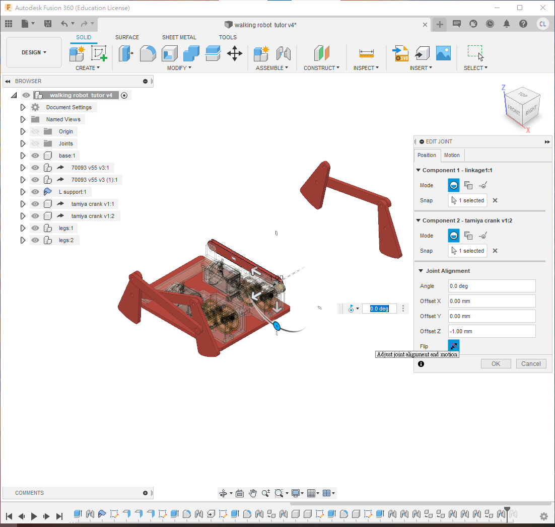
Step 16: Connect the Right Crank
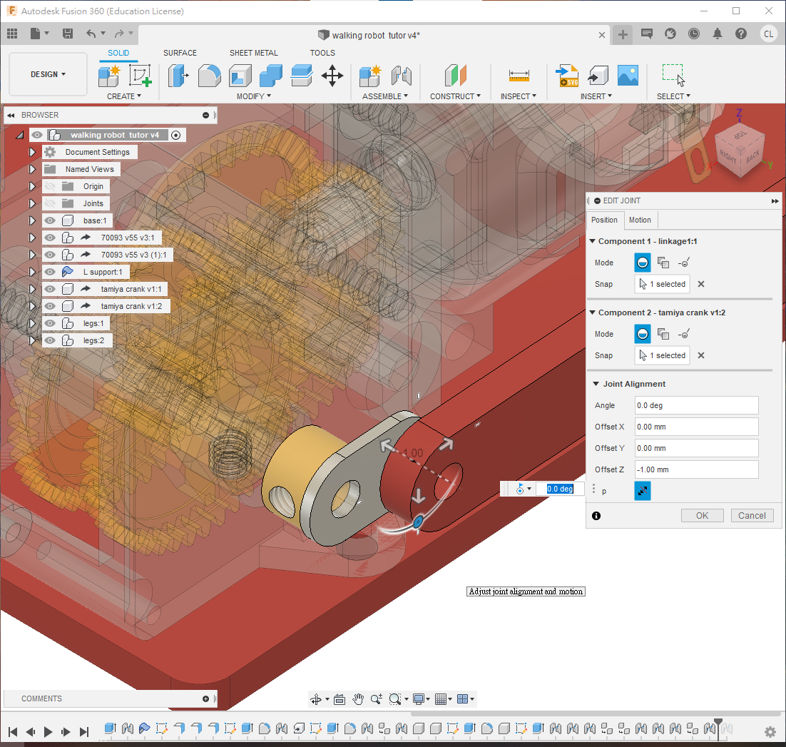
Joint the linkage nearest the right crank to its crank hole with Revolute motion and 1 mm offset.
Step 17: Connect the Right Support
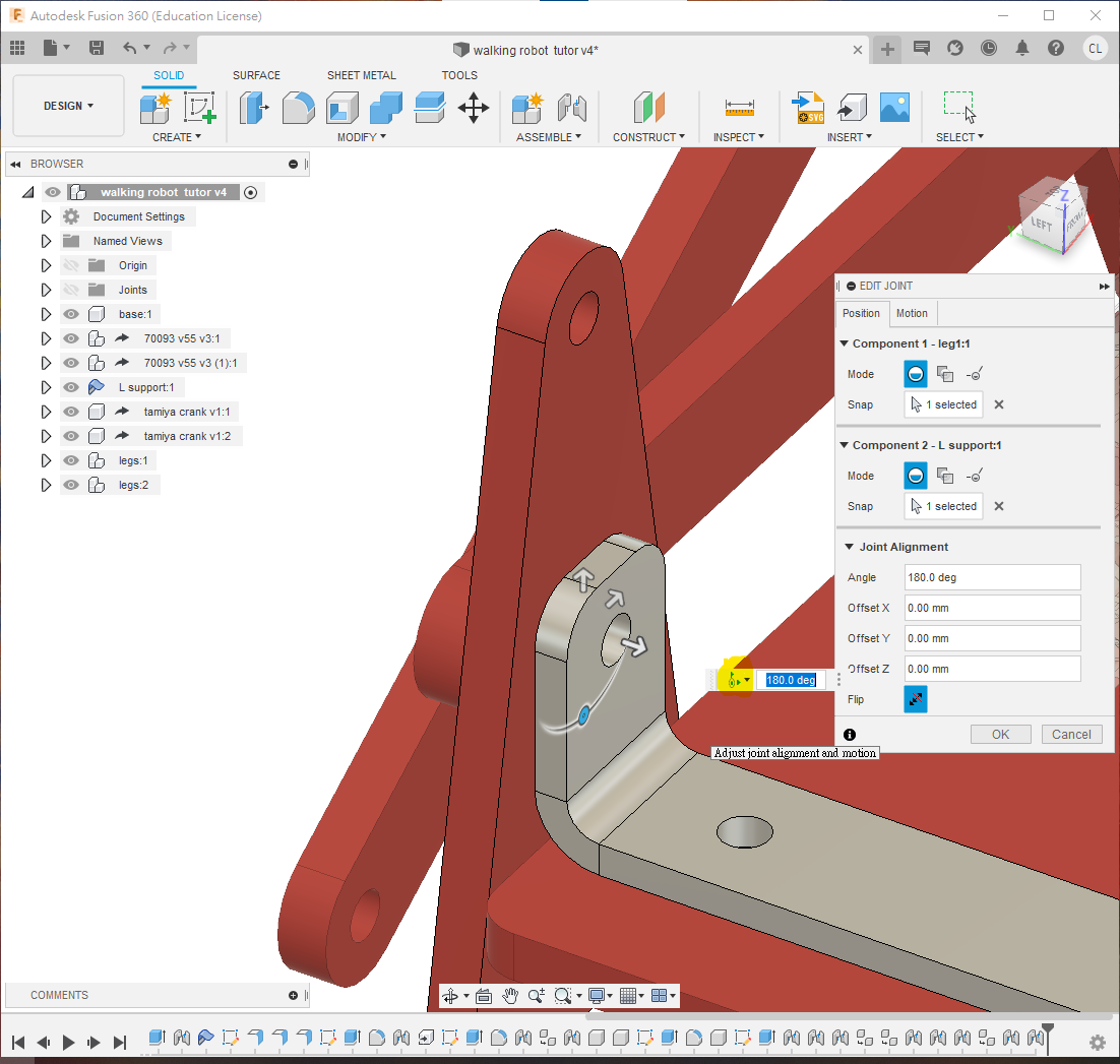
Joint the remaining right-side leg to the unused hole in L support. Choose Cylindrical motion and no offset so it can self-align with the previous connections.
Complete
- Rotate the right-side mechanism and confirm that the complete linkage moves realistically.
- Change spacing parameters and check that the timeline remains free of errors.
- The PDF includes Phase 1 and Phase 2 dimensions. Change the parameters to confirm that the whole design updates immediately.
Translation notice: This English page was generated automatically by AI and has not yet been reviewed by a human. It will be checked and revised page by page when time permits.