Sumo Robot
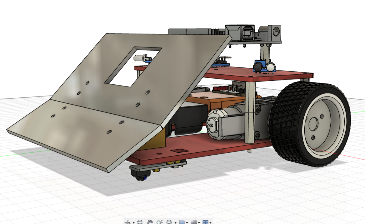
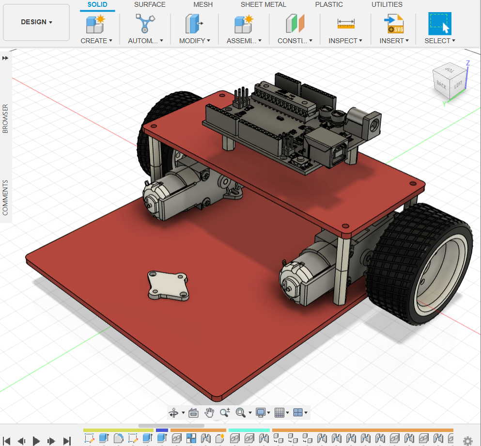
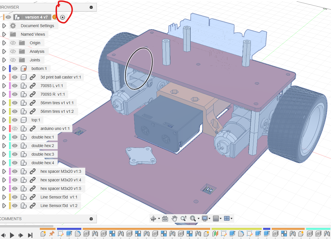
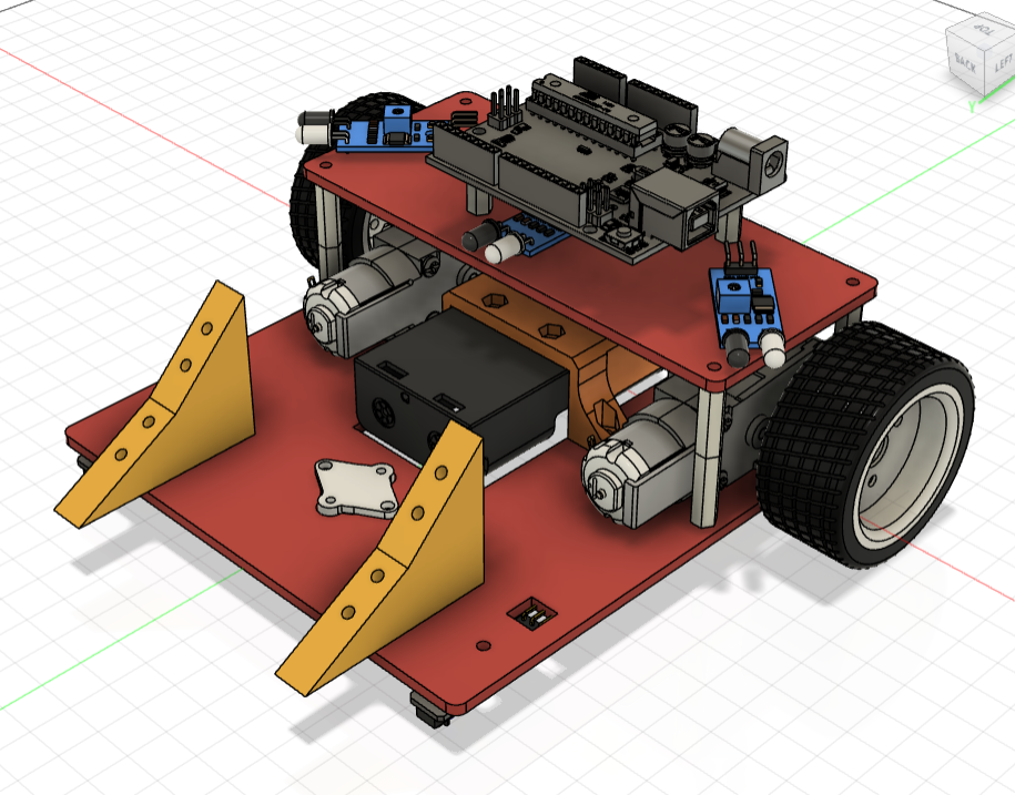
This chapter assembles the sumo robot shown below.
Step 1: Preparation and Files
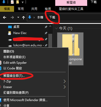
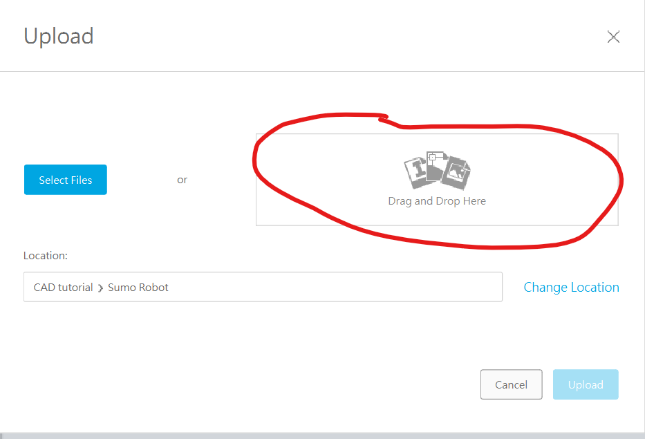
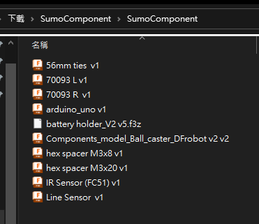
Download and extract the component archive. In Fusion's Data Panel, click Upload and drag the extracted files into the upload area.
Step 2: Build the Chassis
Draw the Bottom Plate
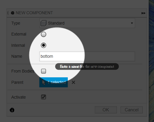
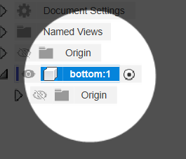
Start a new design and create a component named bottom.
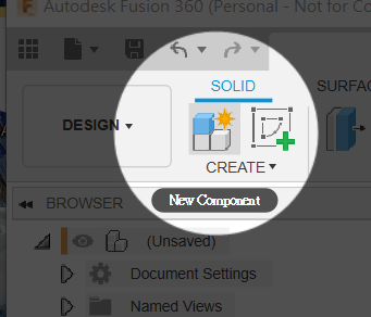
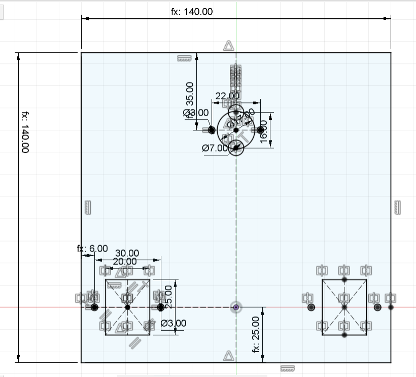
Activate bottom, create a sketch and follow the dimensioned drawing.
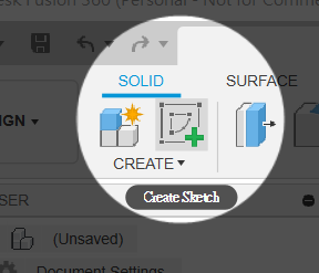
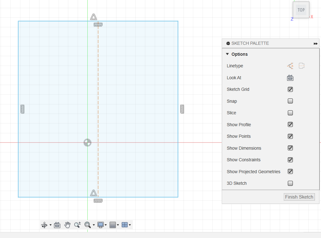
Draw a rectangle with R and a vertical centreline with L. Apply Coincident between the centreline and origin.
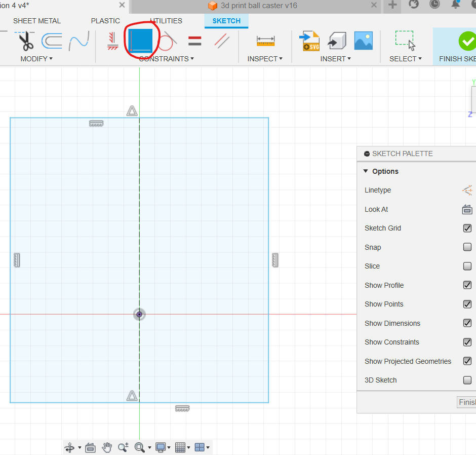
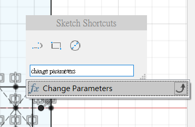
Open Change Parameters and add thickness, carLength, carWidth, gearBoxLength, gearBoxWidth and ballCastorLength with the values shown. Parameter names cannot contain spaces; values may include units or expressions.
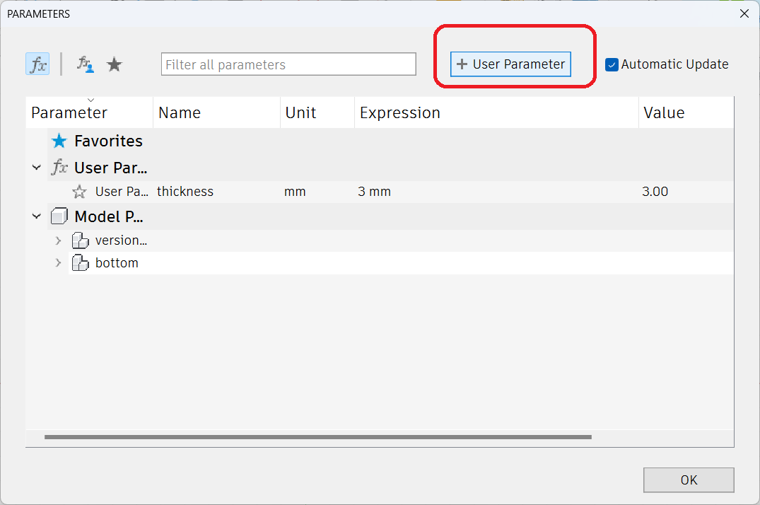
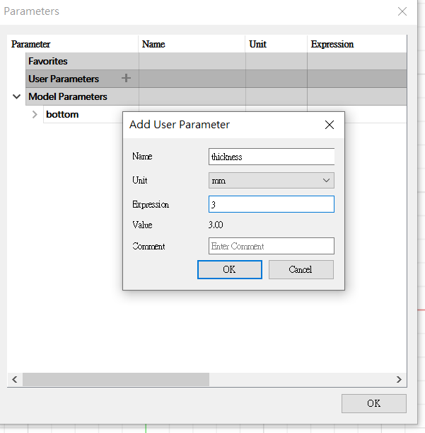
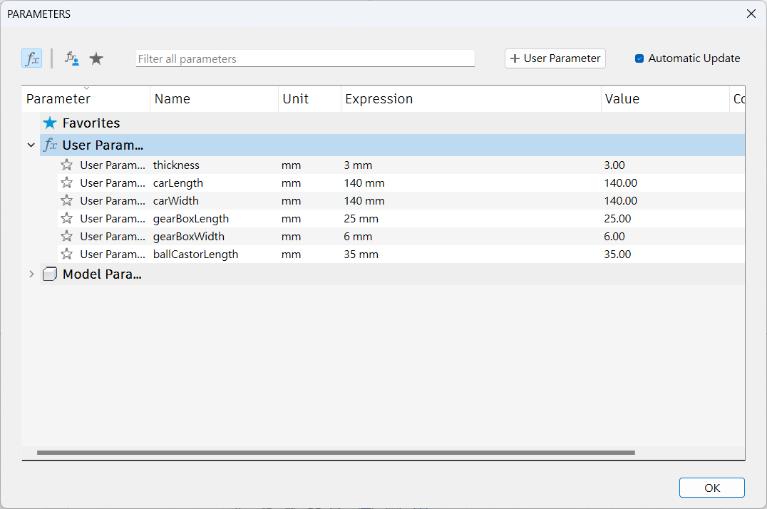
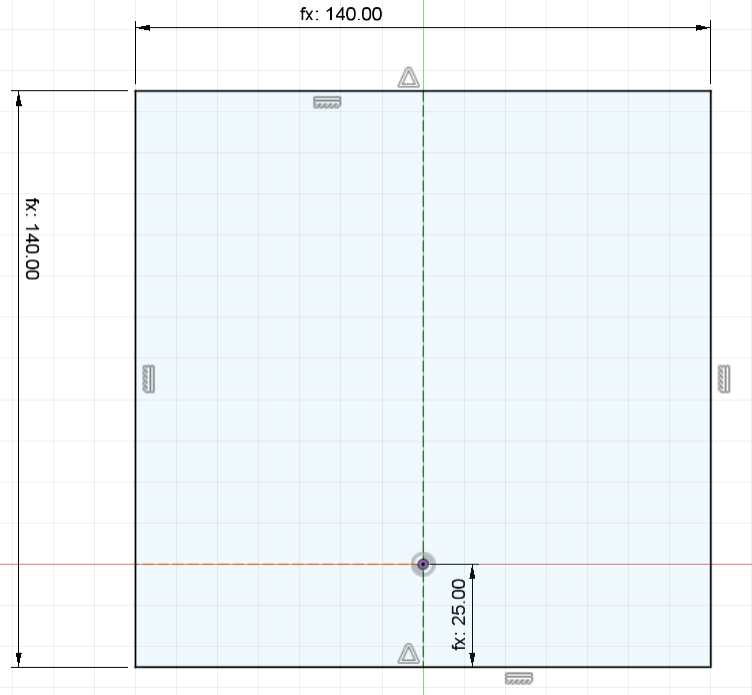
Set rectangle length and width to carLength and carWidth, and its lower edge to gearBoxLength from the origin. Fully constrain the sketch. From the origin, draw a horizontal construction line to the edge, then add a centre rectangle and two circles. Add a centreline, make the circles Equal and Symmetric, and dimension the layout with gearBoxWidth. Mirror it to the opposite side.
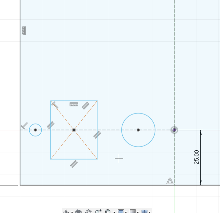
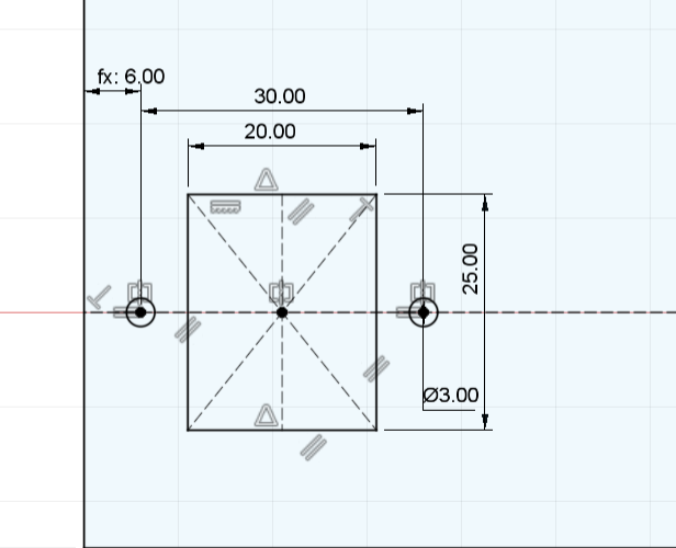
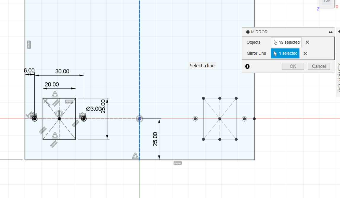
Draw the upper geometry about the centreline, using Equal and Symmetry.
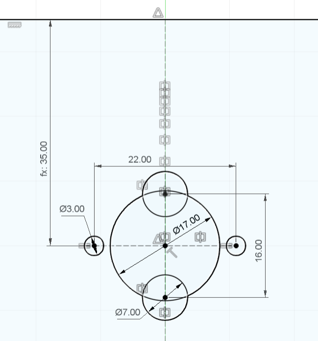
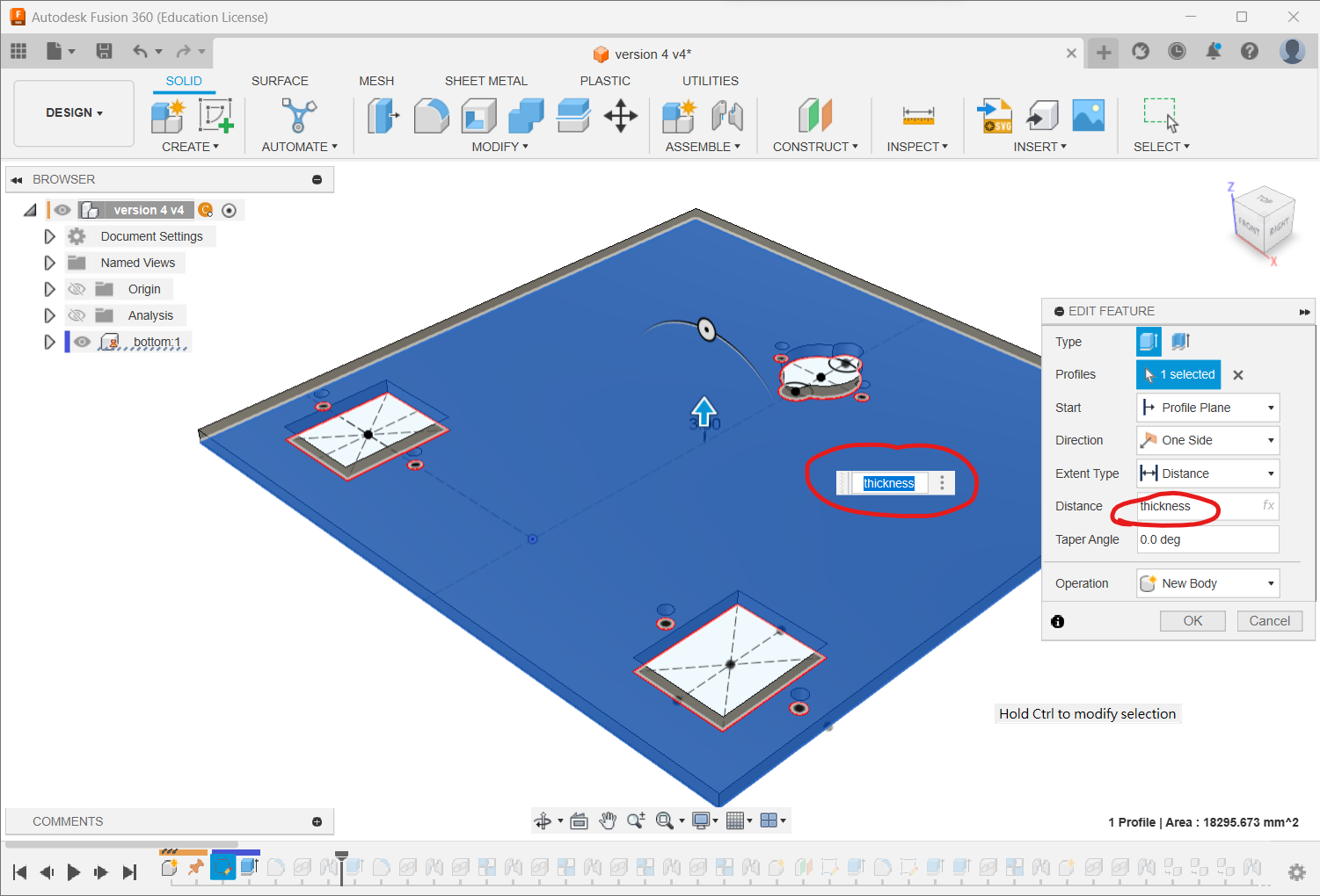
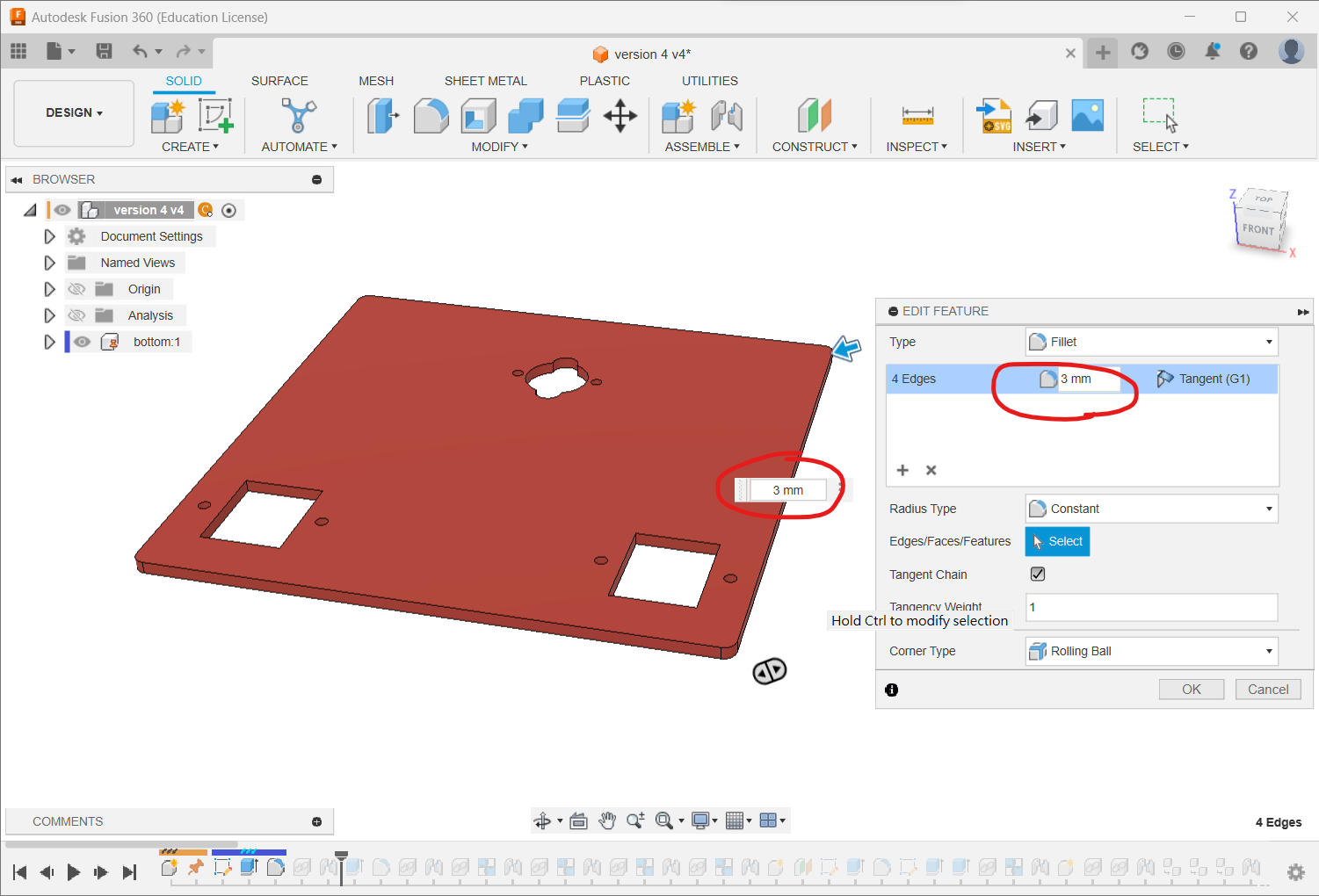
Extrude by thickness and fillet the four corners to 3 mm so the manufactured plate has no sharp corners.
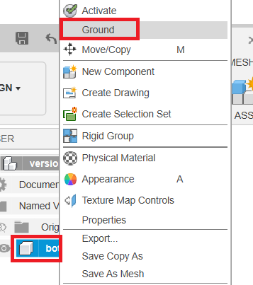
Right-click bottom and choose Ground. All later joints will then be referenced to this fixed component.
Insert Chassis Components
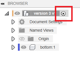
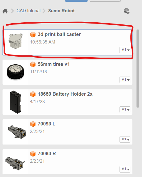
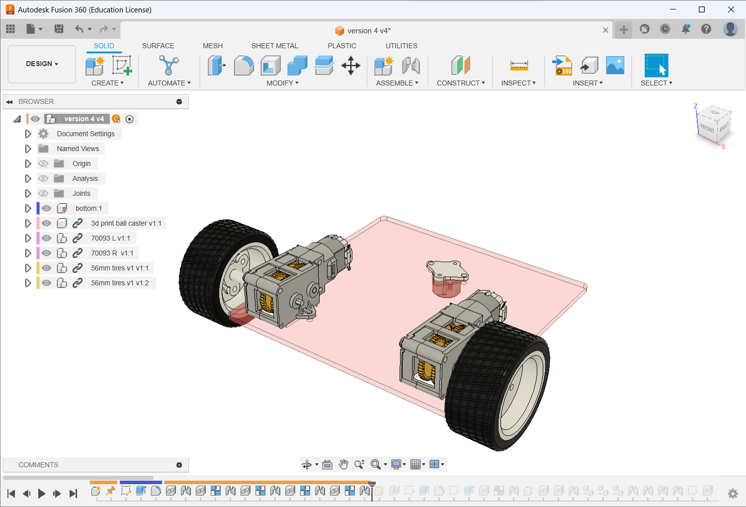
Reactivate the top level. Drag the ball caster from the uploaded library into the design and joint it to the chassis.
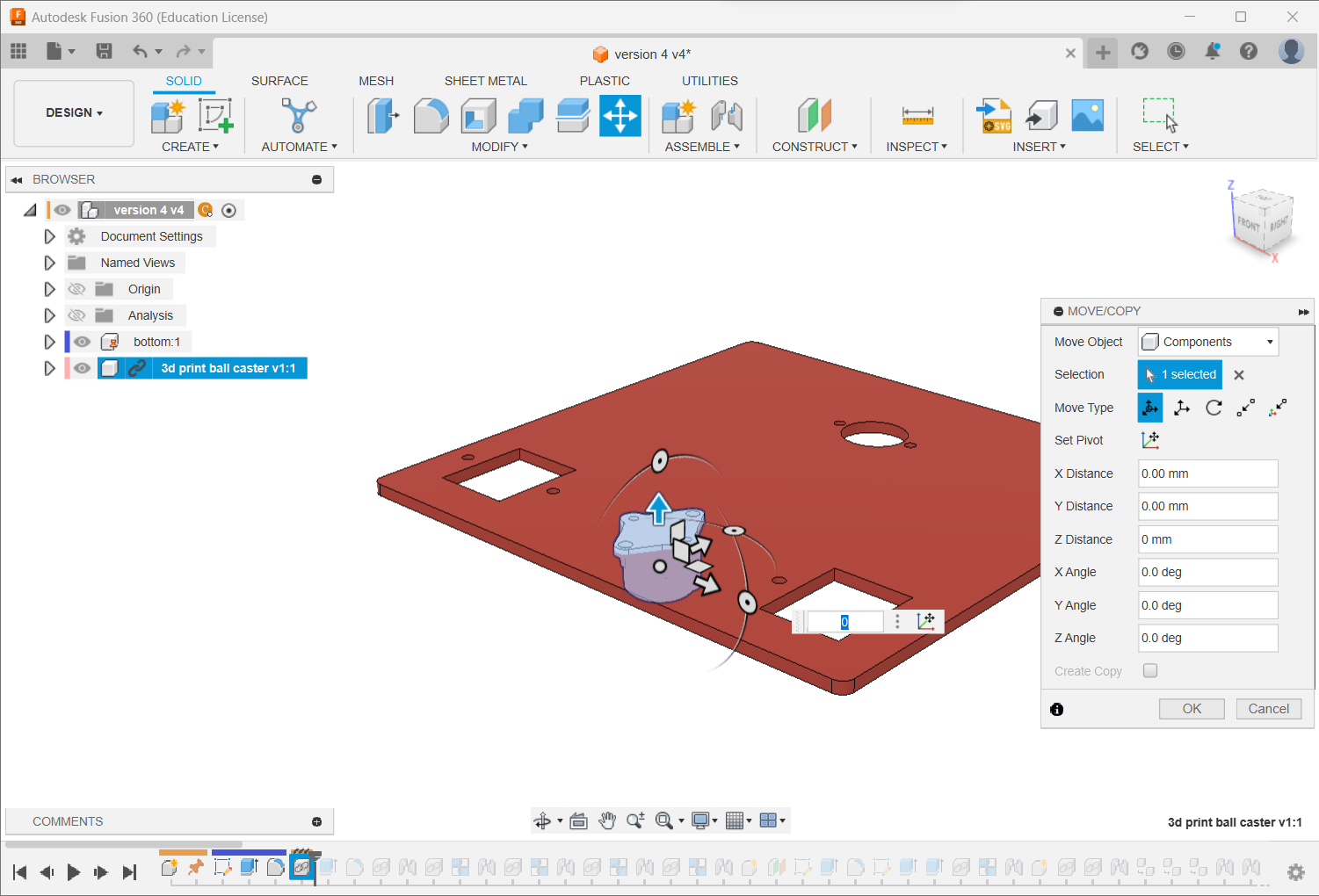
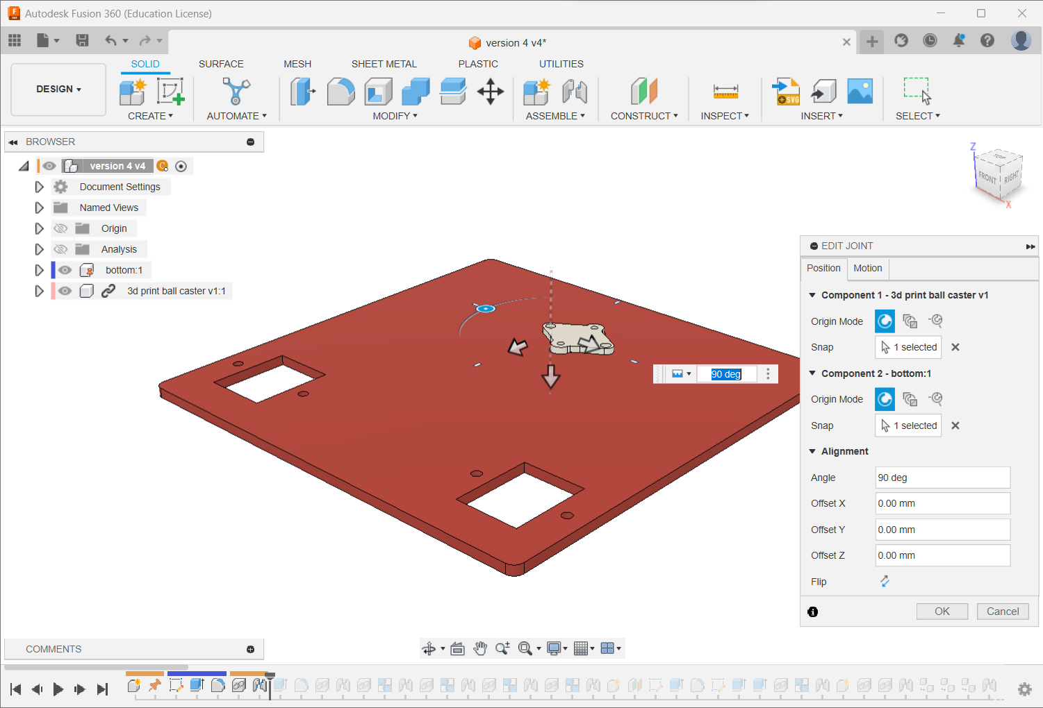
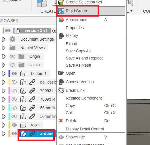
Insert 70093L, right-click it in the Browser and create a Rigid Group, then joint it to the bottom plate.
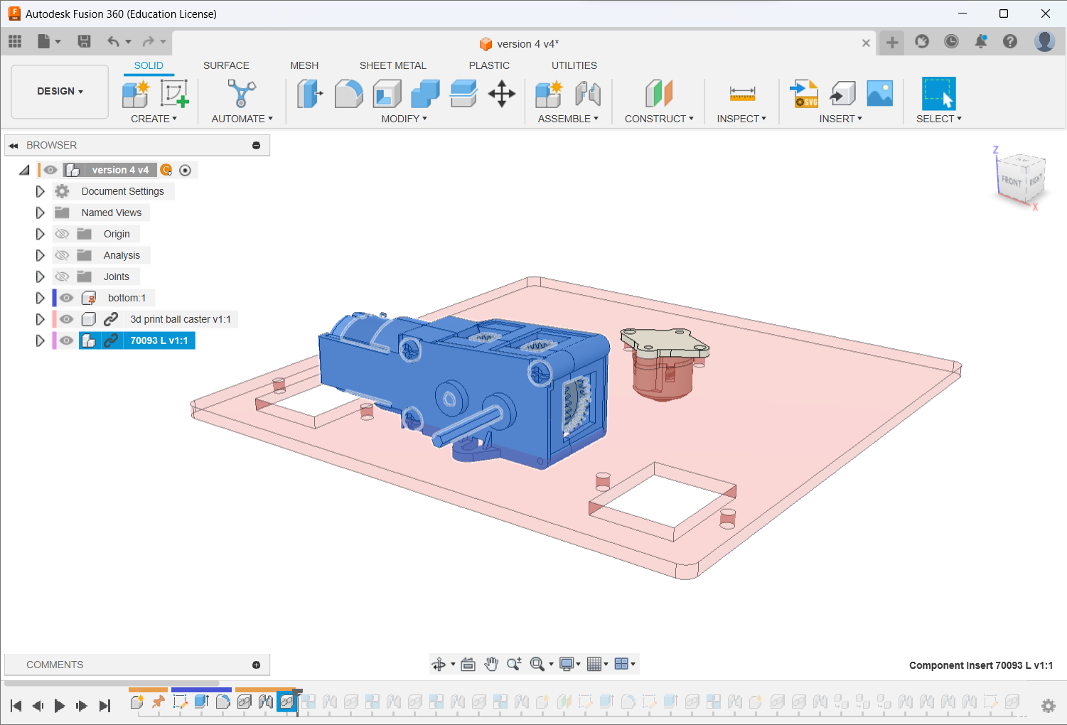
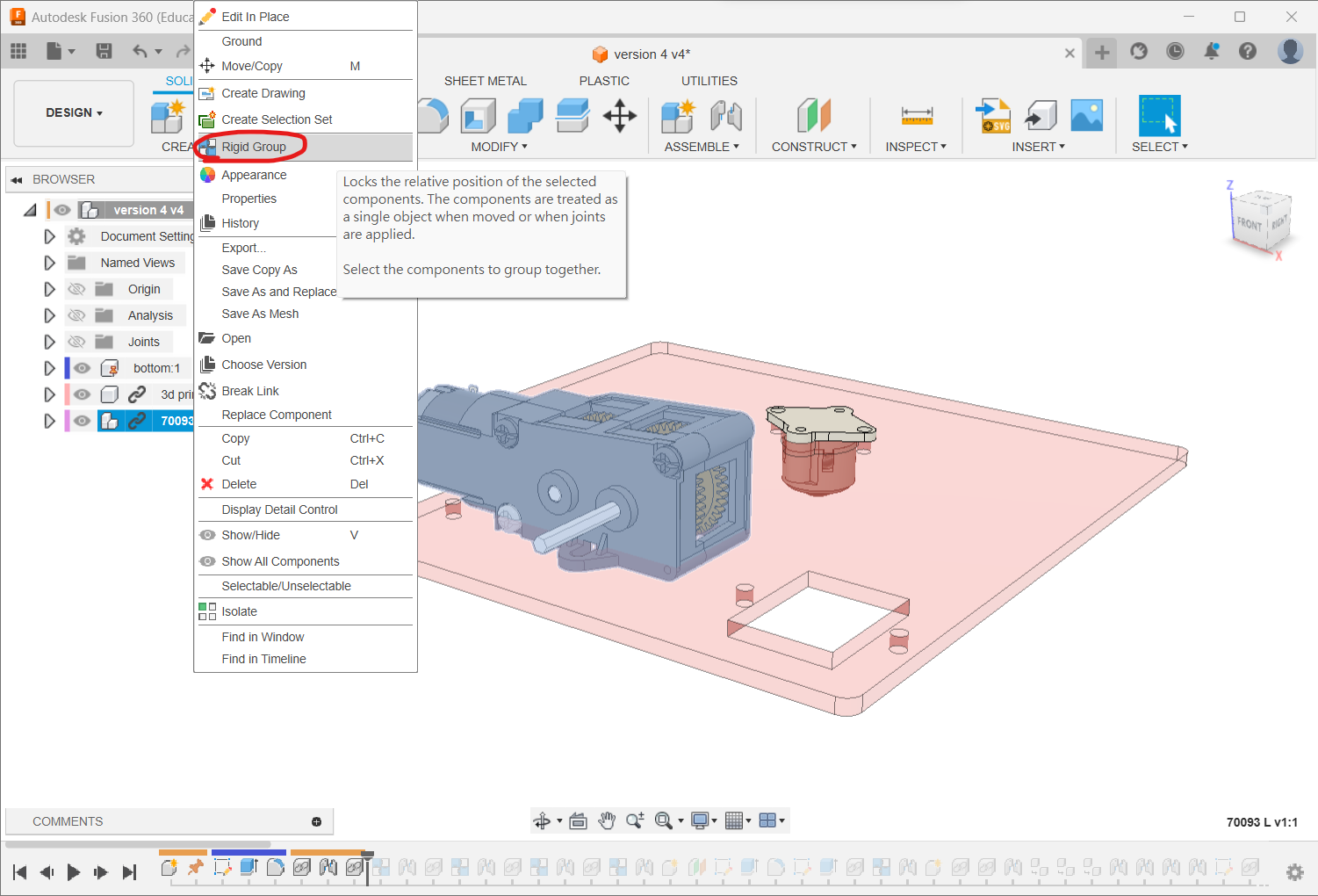
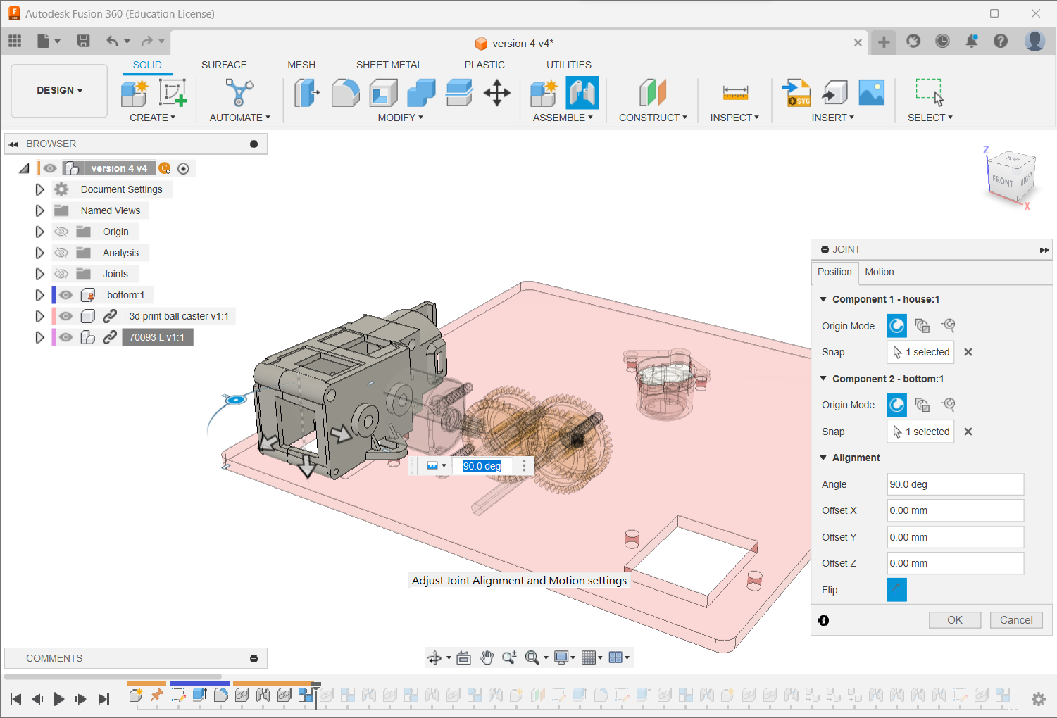
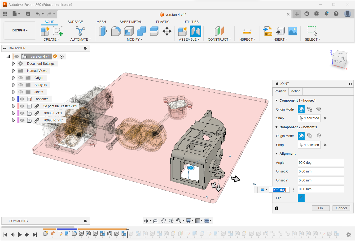
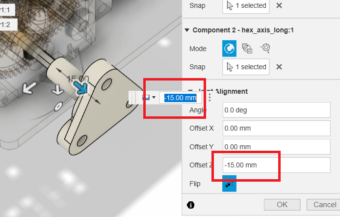
Repeat for 70093R and both Tamiya 56 mm sport tyres. Joint each tyre at the gearbox hex-shaft centre with a 15 mm offset and Revolute motion.
Step 3: Create and Assemble the Upper Plate
Draw the Top Plate
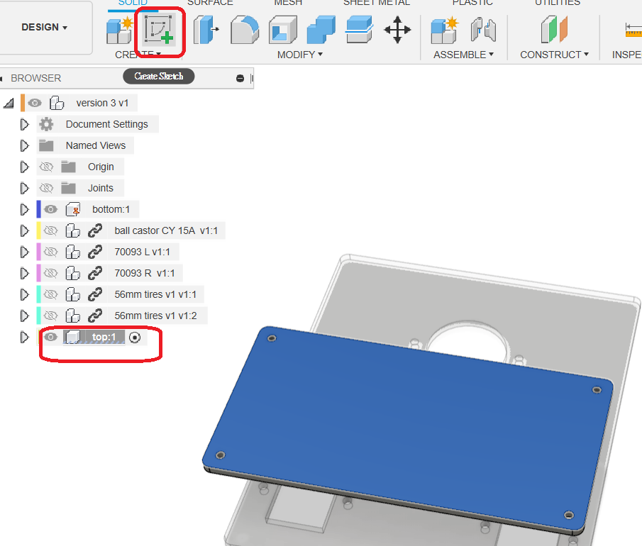
At the top level, create a component named top.
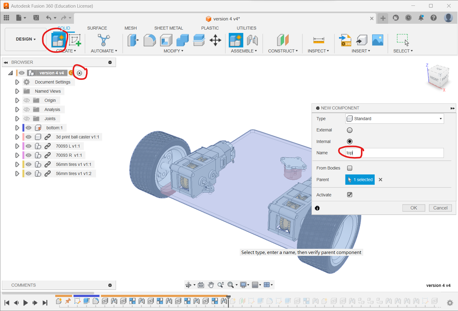
Activate it and create an Offset Plane 40 mm above the bottom plate. The workshop provides 20 and 8 mm hex spacers; combine available sizes or add printed spacers when another height is required.
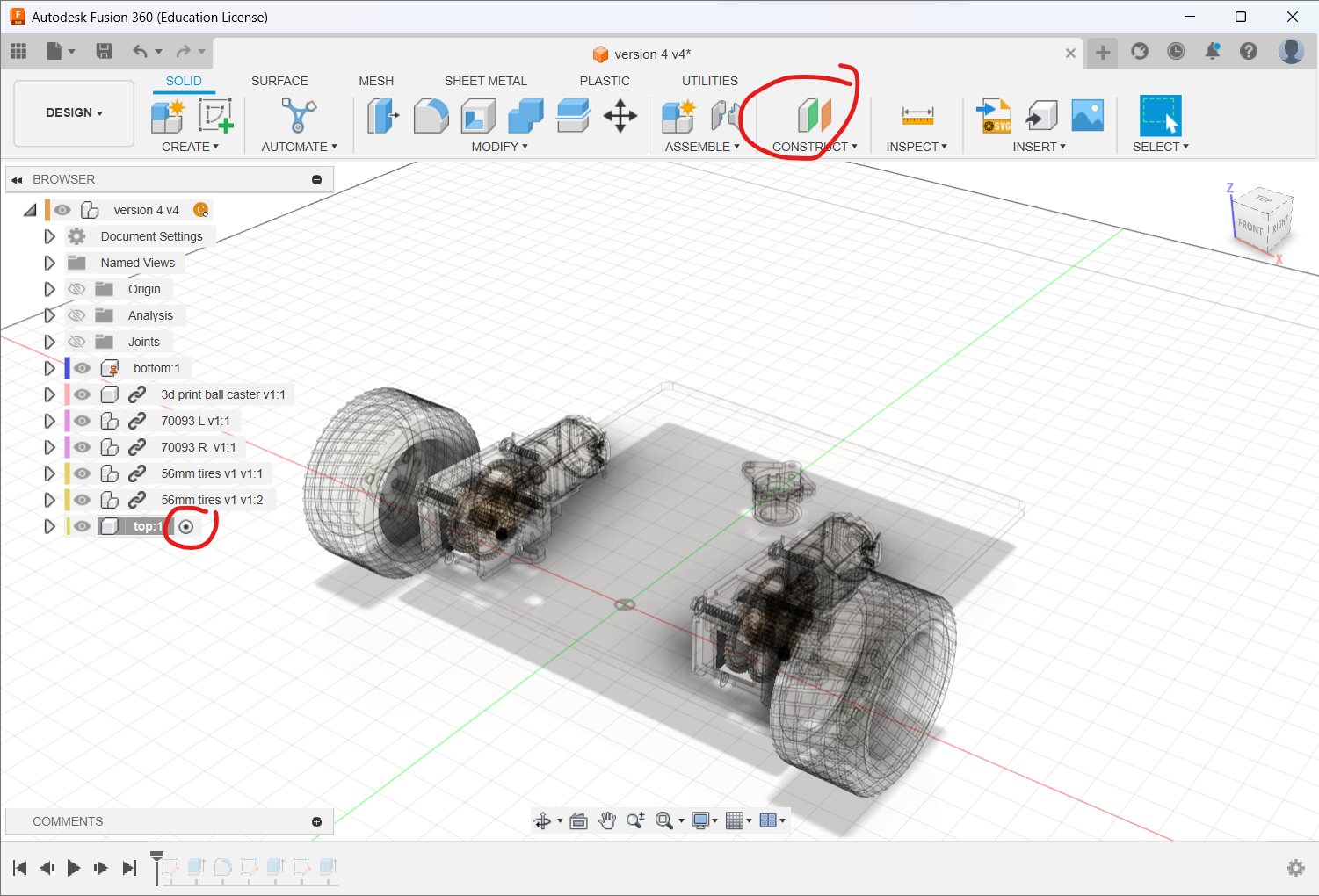
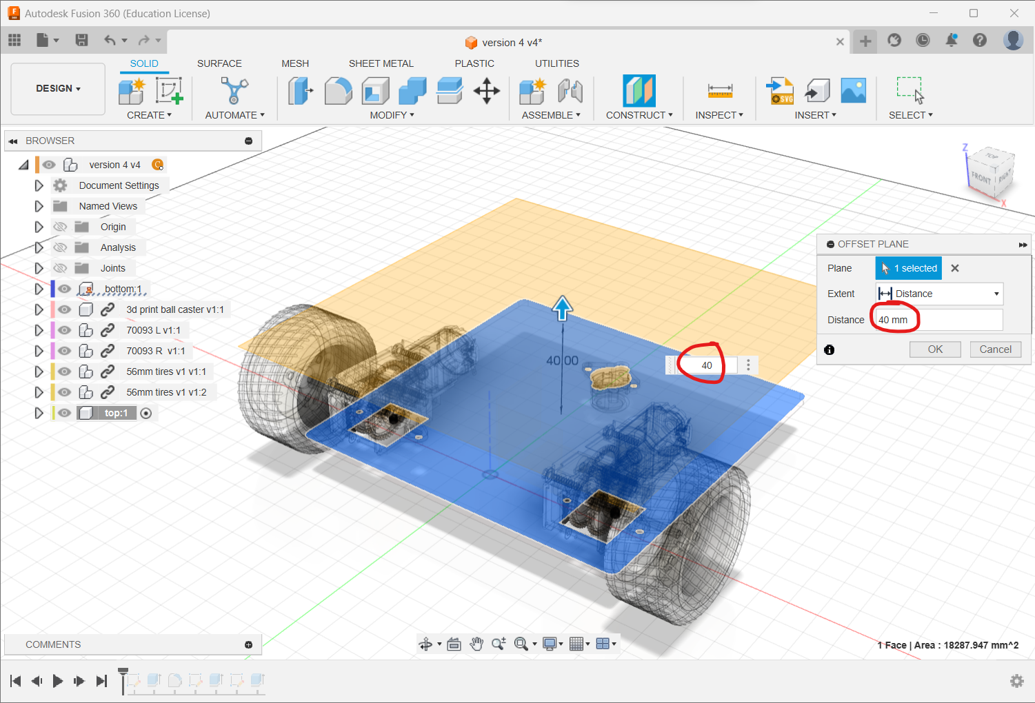
Sketch on the plane and press P to project the bottom plate.
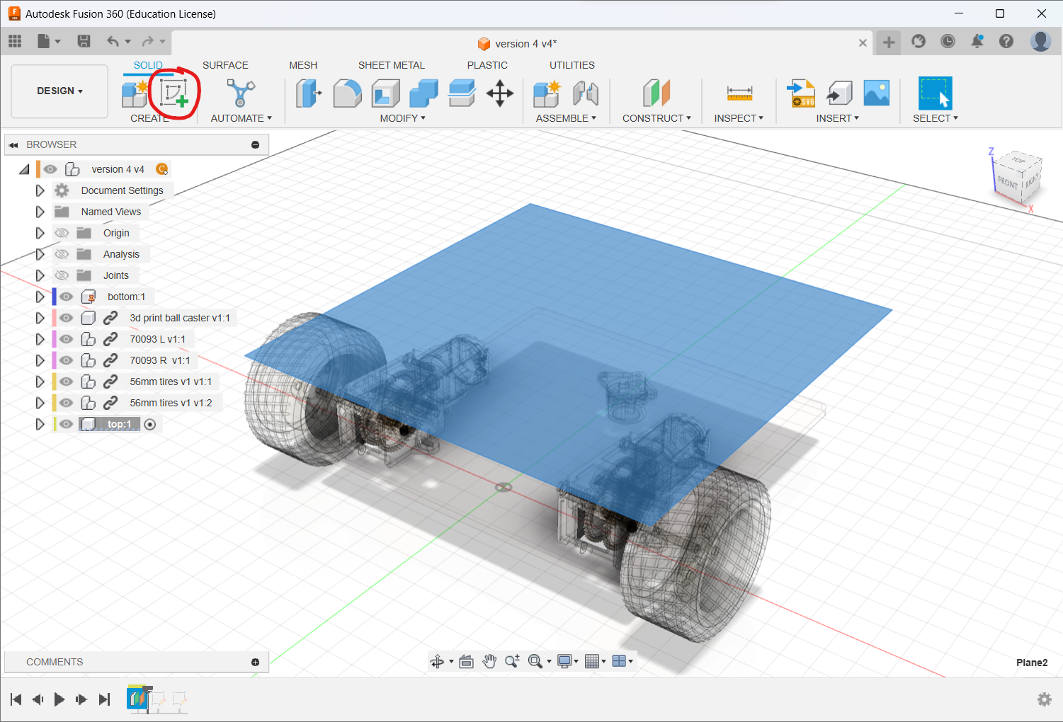
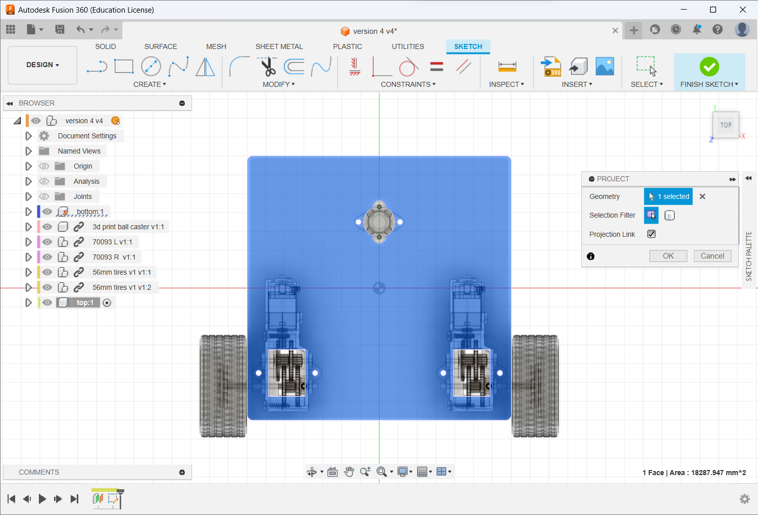
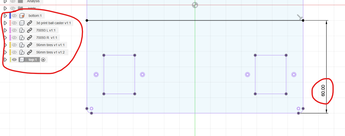
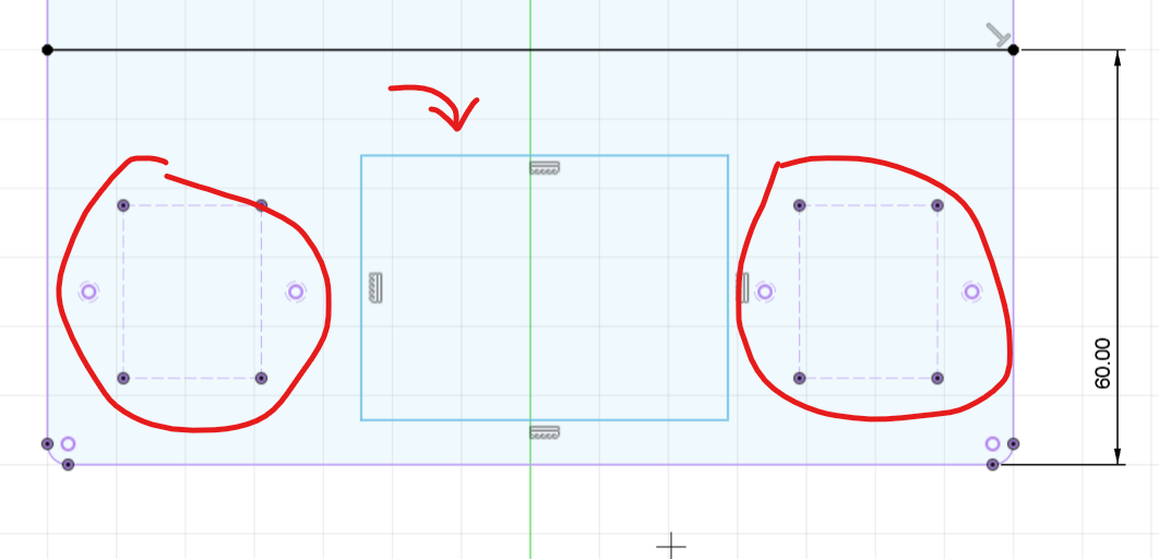
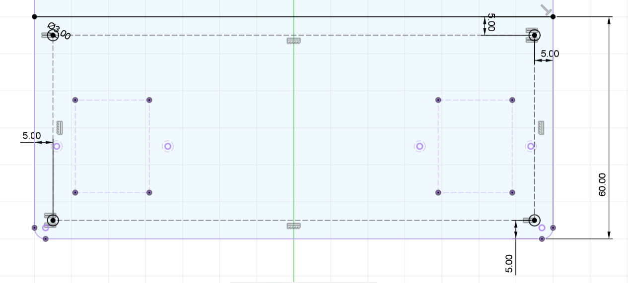
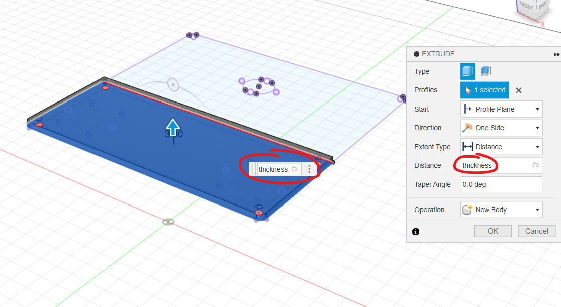
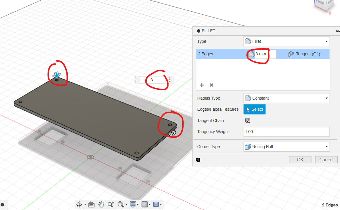
Hide other components. Draw a horizontal line 60 mm from the bottom edge. Convert the gearbox mounting geometry and two rectangles to construction geometry. Create the top outline 5 mm inside the required boundaries, place four Equal Ø3 mm mounting holes at the corners, extrude by thickness, and fillet the remaining sharp corners to 3 mm.
Install the Arduino UNO
With top active, sketch on its top face and create parameters unoX and unoY for the UNO position.
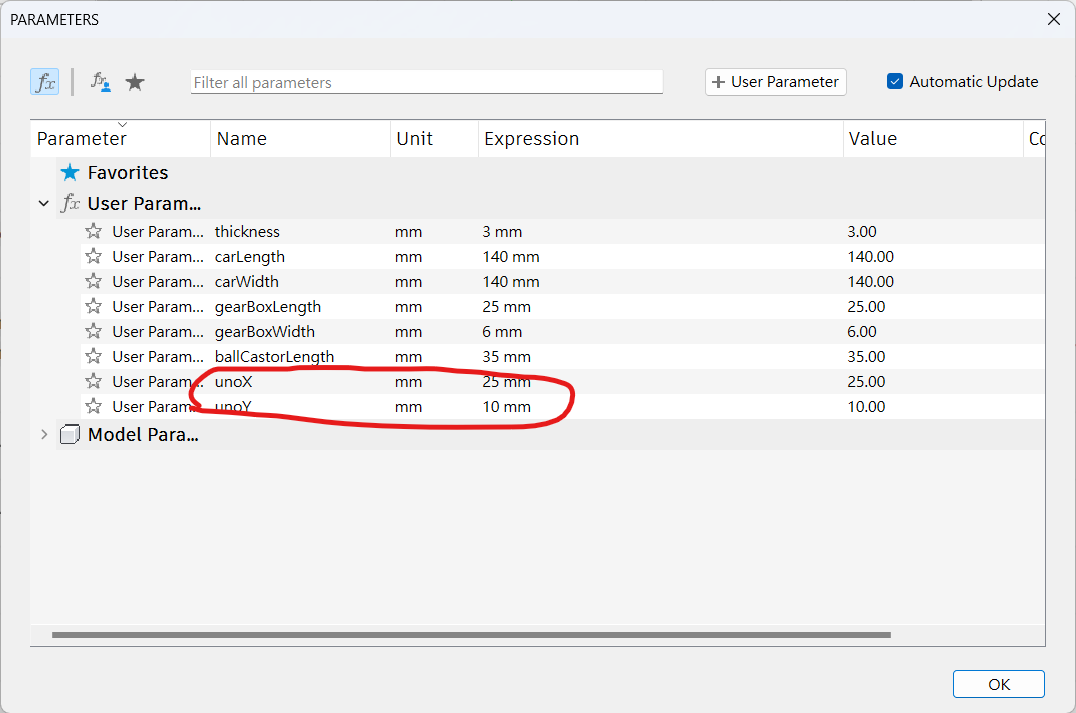
Using the inch-derived UNO dimensions shown, draw three Equal Ø3 mm holes. The fourth is omitted because it lies too close to another top-plate feature. Locate them with unoX and unoY, then cut the holes.
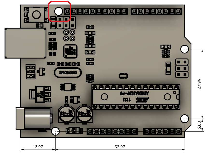
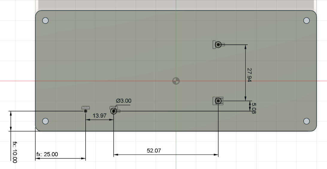
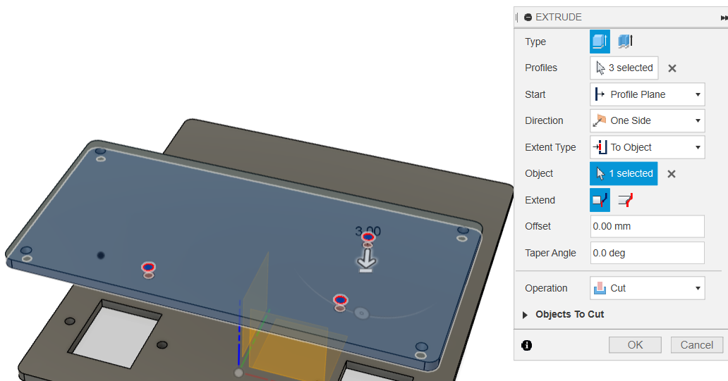
Show the sketch containing the four chassis-spacer holes and extrude them down through the bottom plate as well.
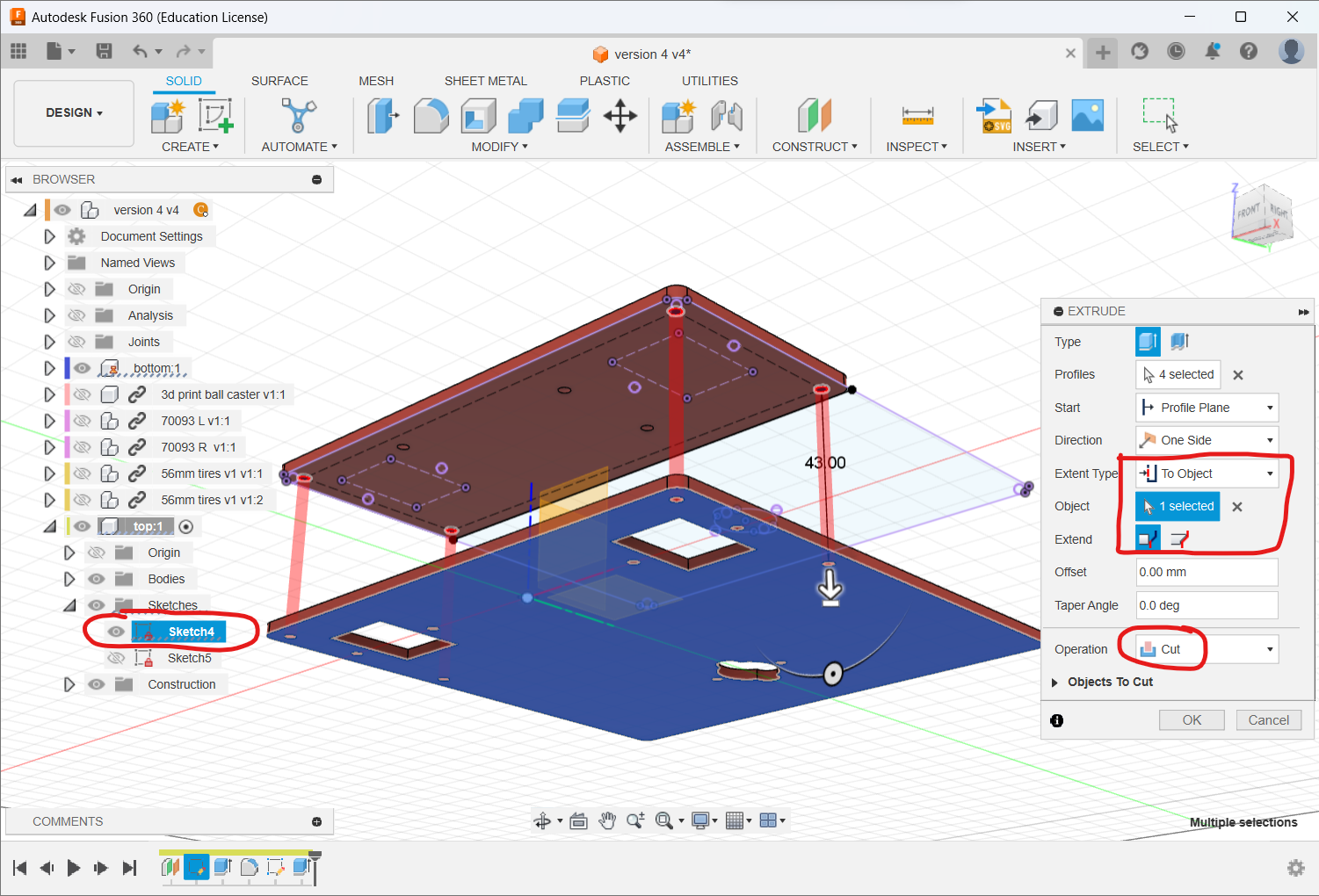
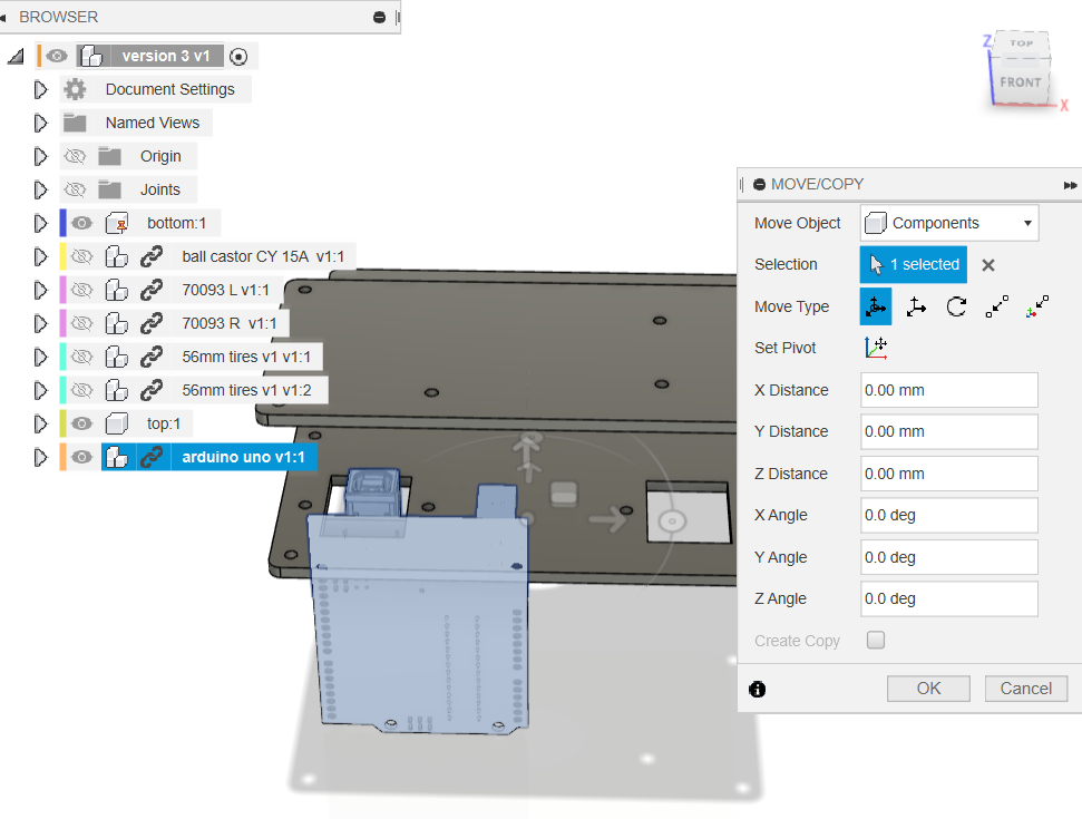
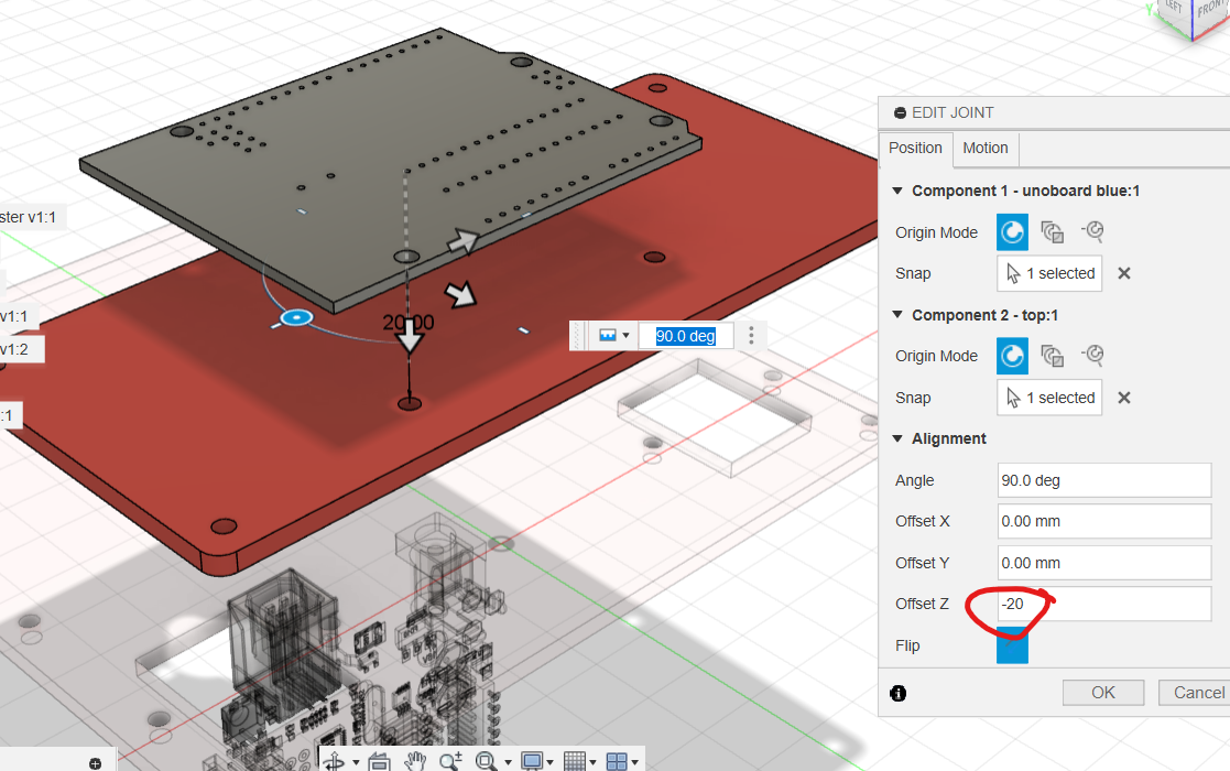
Insert the Arduino UNO, make its parts a Rigid Group, and joint it to the top plate with 20 mm offset.
Insert Hex Spacers
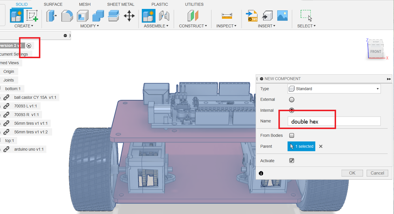
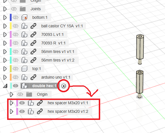
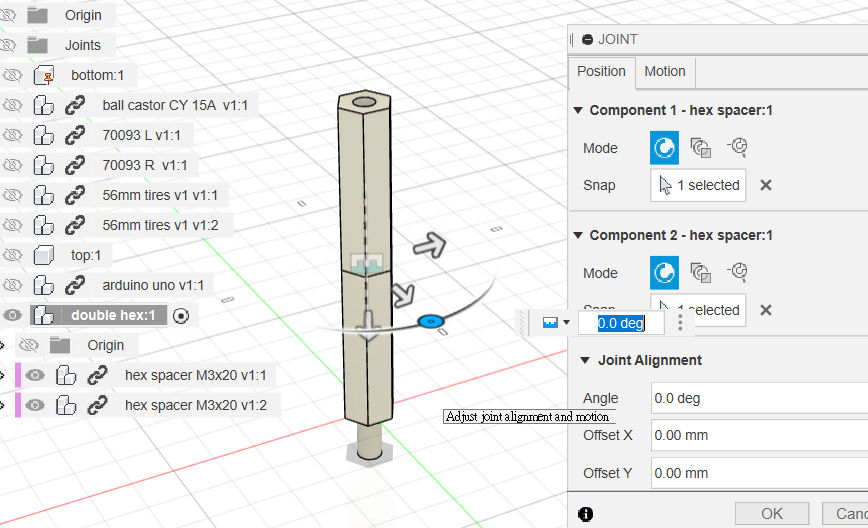
At the top level create double hex. Activate it, insert two hex spacer M3x20 occurrences and joint them end-to-end.
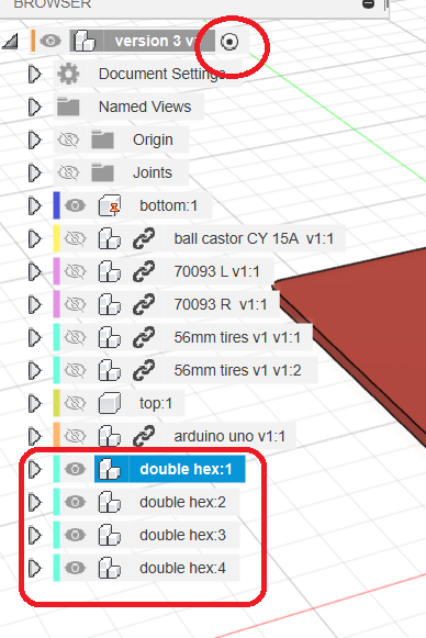
Copy it three times and joint all four assemblies to the chassis.
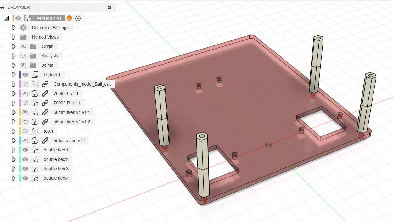
Copy one 20 mm spacer three times and joint those three spacers to the UNO holes.
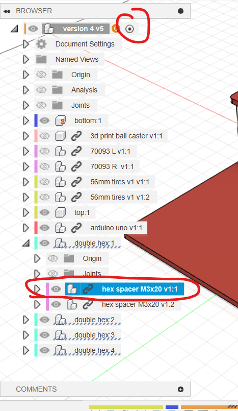
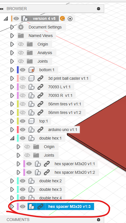
After assembly, drag parts gently to confirm that every intended component is fixed.
Step 4: Install Sensors and Battery
Cut the Bottom Plate
Create sensorX, sensorY and batteryY to control line-sensor and battery-holder locations.
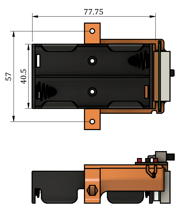
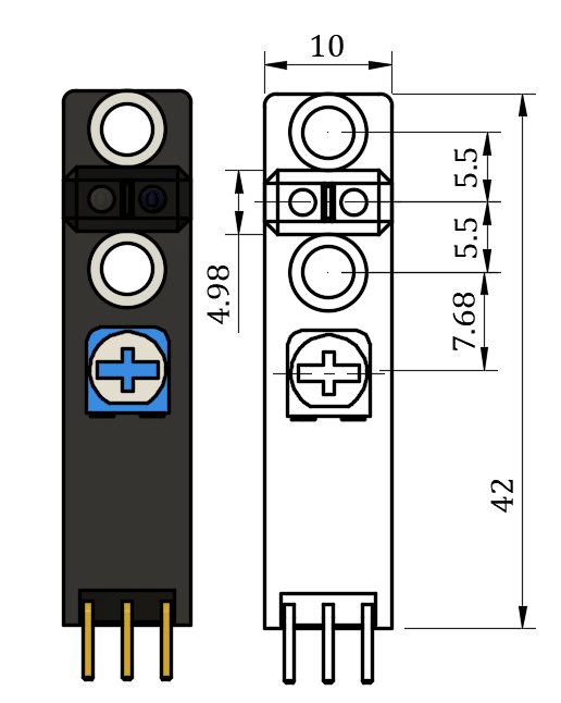
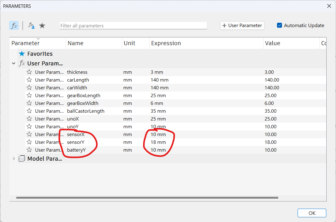
Activate bottom, sketch on it and hide other components.
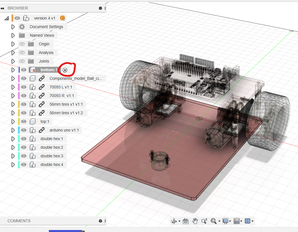
For one line sensor, create two mounting holes: the lower hole is positioned by sensorX and sensorY, and the upper is 11 mm above it. Join their centres with construction geometry and add an 11 × 5.5 mm centre rectangle at the midpoint. Add an 8 × 8 mm opening 8 mm from the lower hole for resistor adjustment, plus the indicated wiring rectangle and round hole.
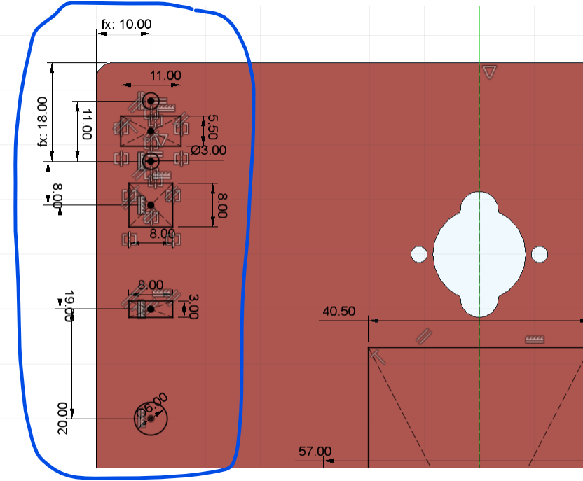
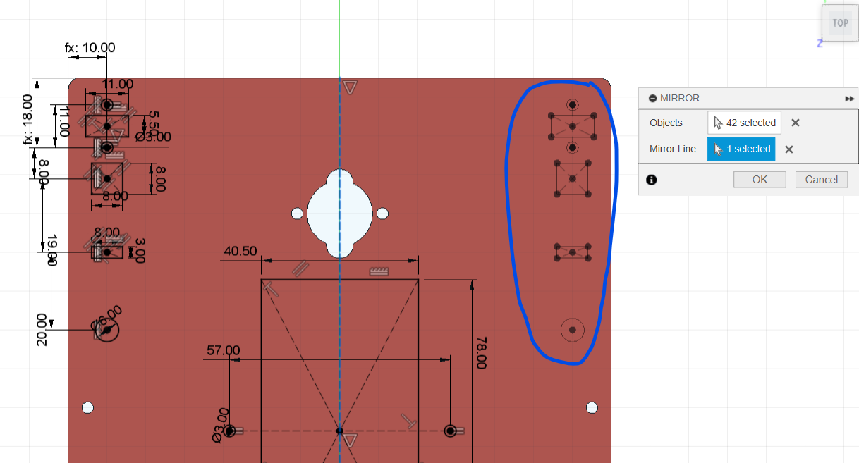
Create a chassis centreline and mirror the complete sensor geometry to the other side.
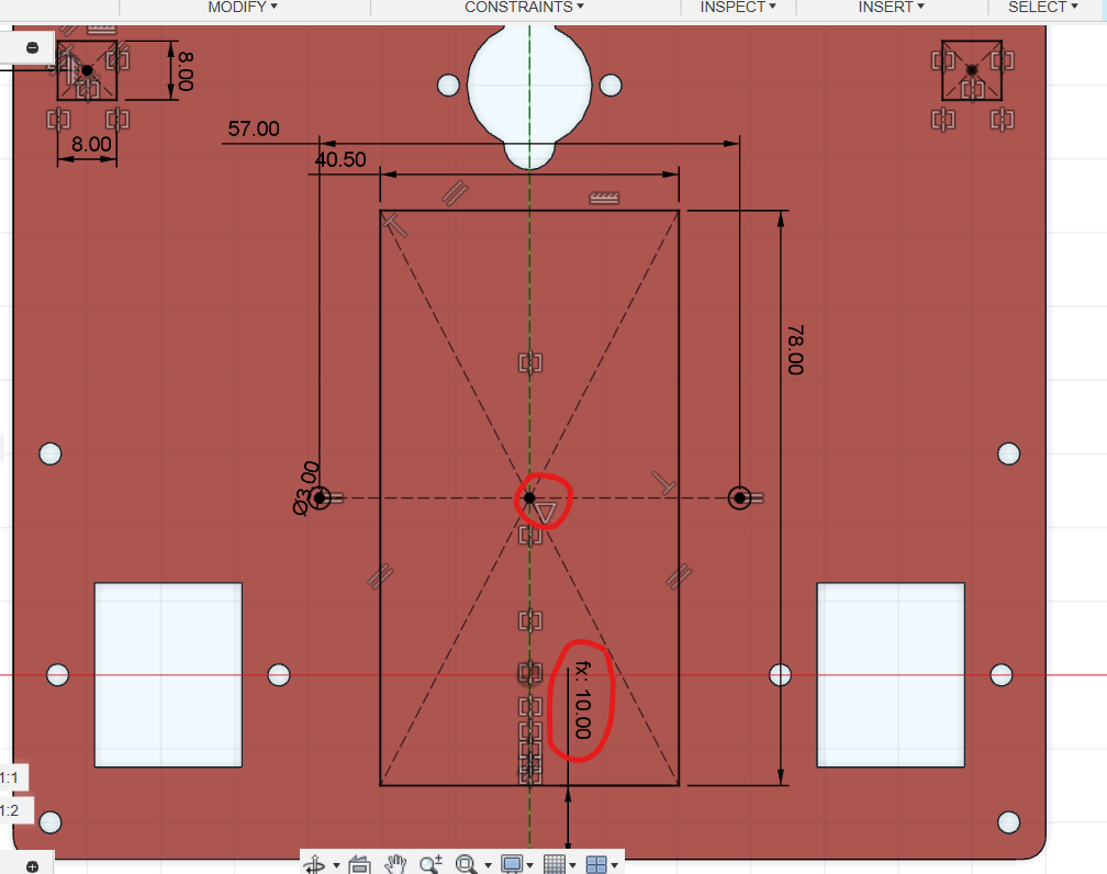
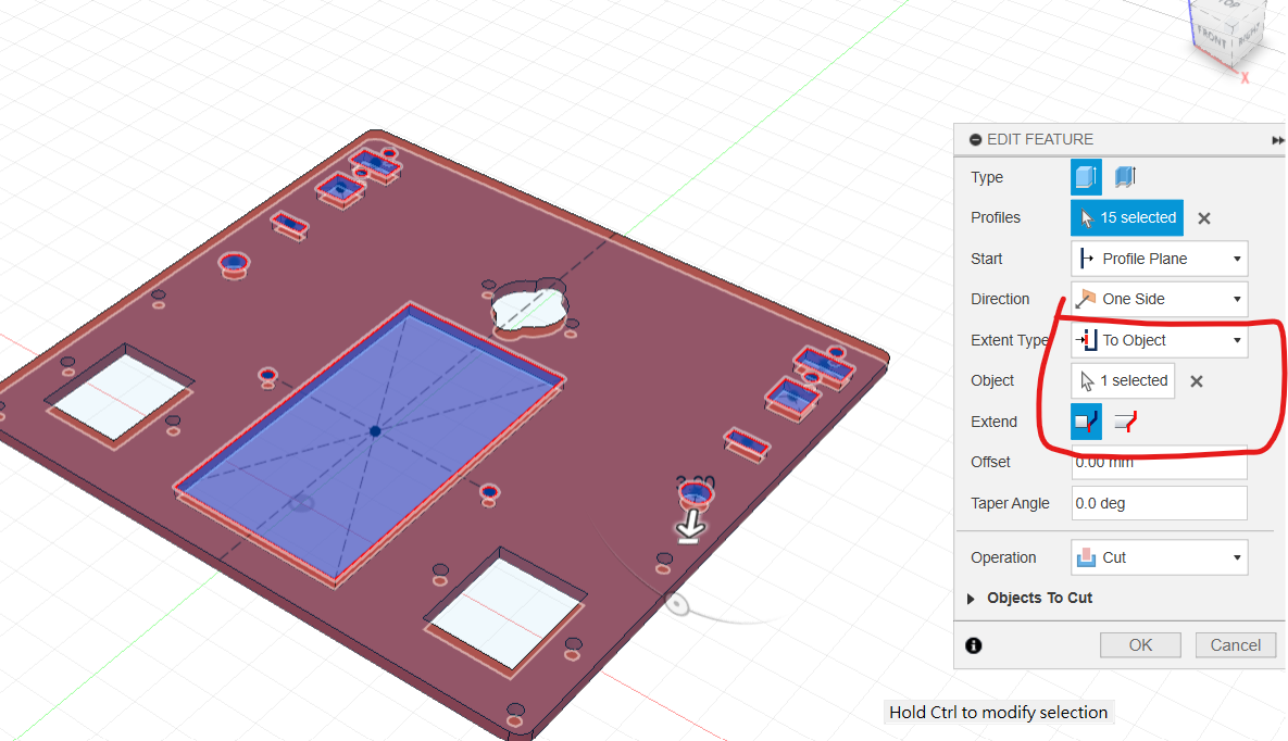
On the centreline, draw the battery-holder rectangle. Add a horizontal line constrained by Midpoint to the rectangle centre, place Equal Ø3 mm holes at its ends, and set the rectangle's bottom position to batteryY. Cut all openings from the plate.
Insert Line Sensors and Battery Holder
Return to the top level. Insert two Line Sensor components and one Battery Shell.
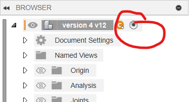
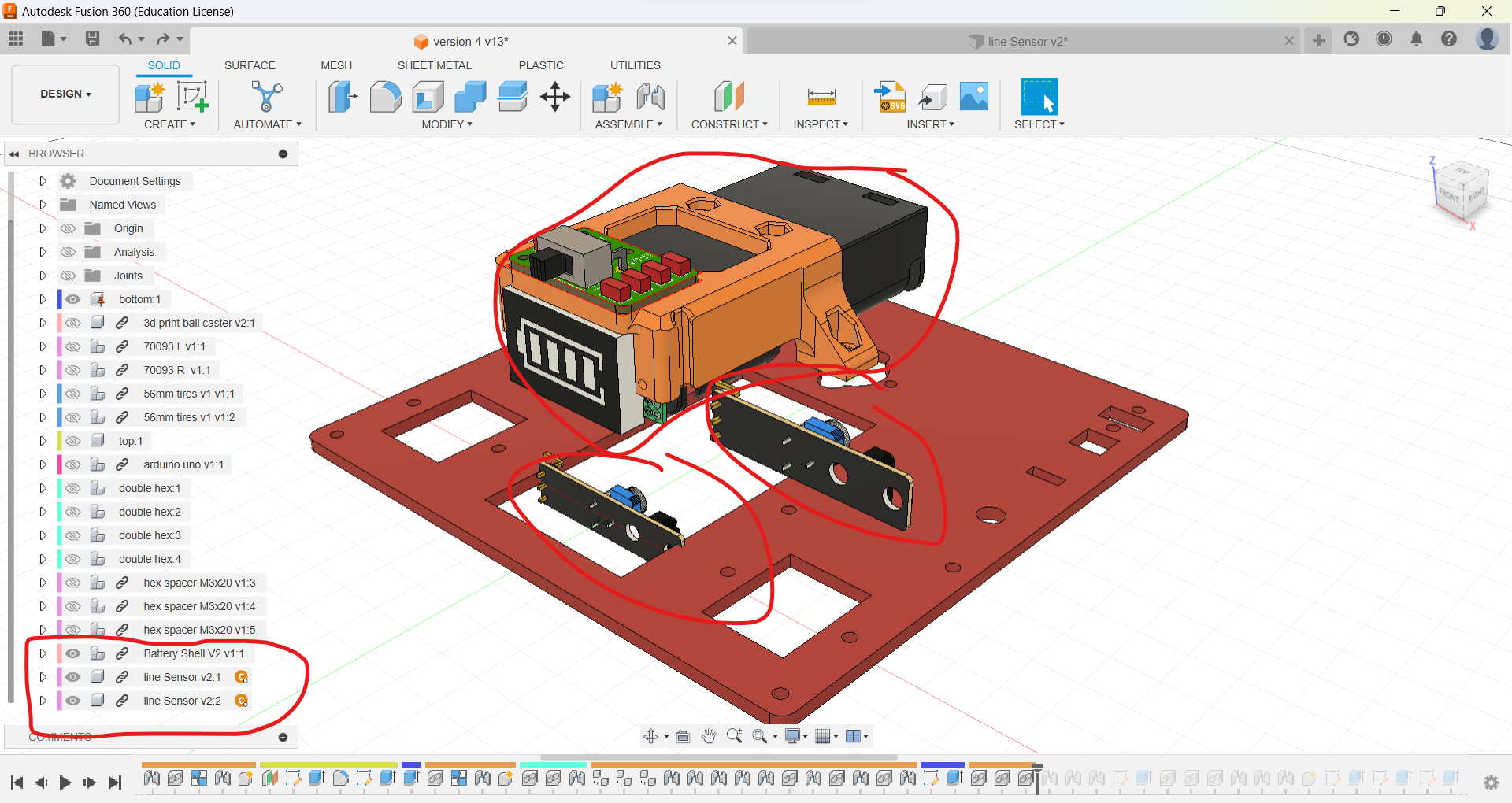
Joint both line sensors beneath the chassis, then install the battery holder and show all components.
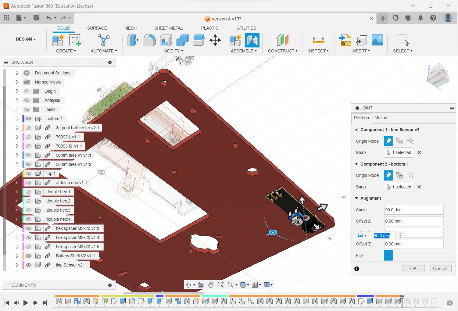
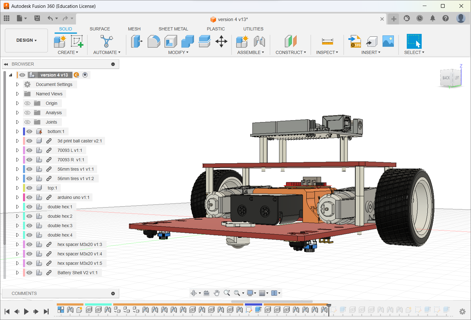
Cut the Top Plate and Install IR Sensors
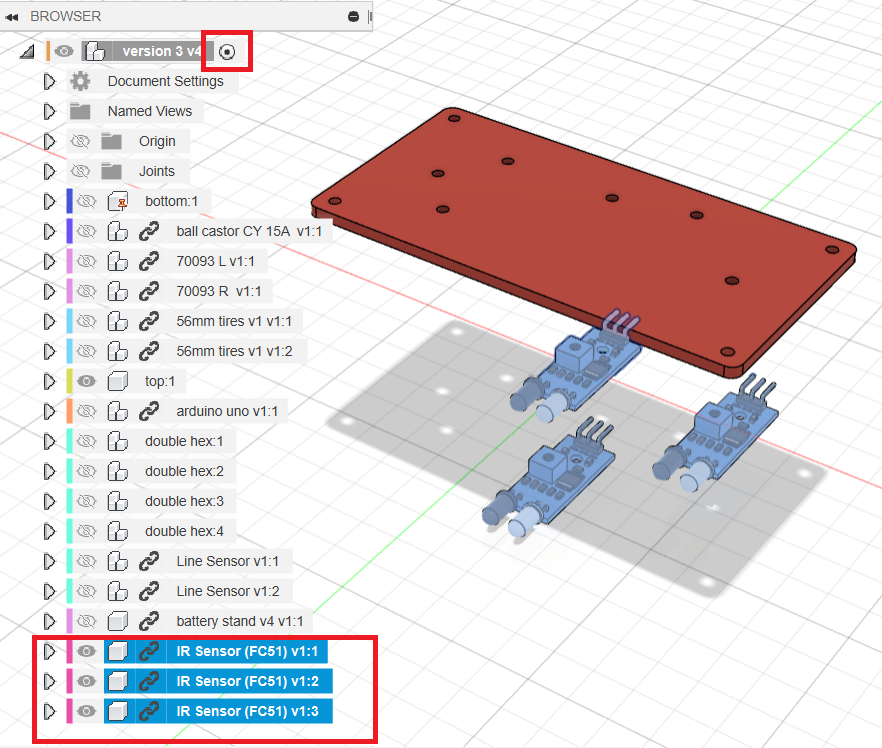
Create IRSensorX and IRSensorY.
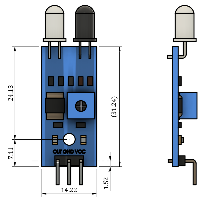
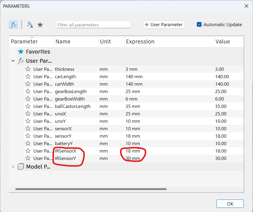
Activate top, hide the UNO/spacers and sketch on the top plate. Draw a construction centreline. Place an Ø3 mm hole using IRSensorX and IRSensorY, mirror it to the other side, and place a third Equal hole on the centreline aligned horizontally with the outer holes. Cut all three.
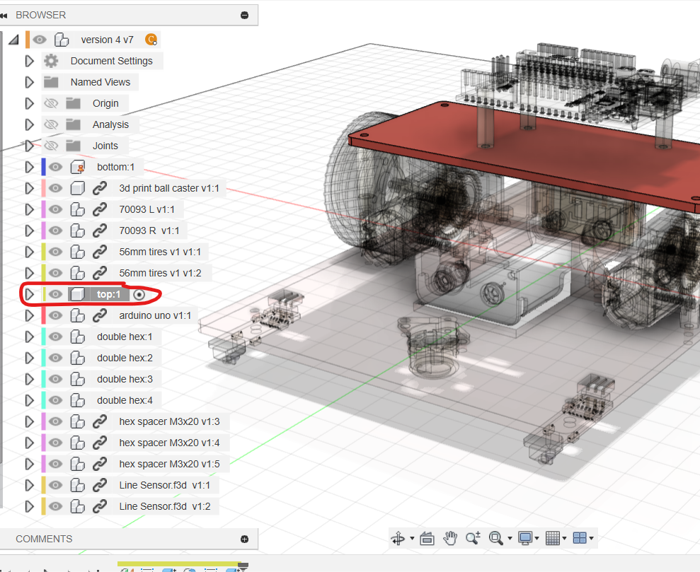
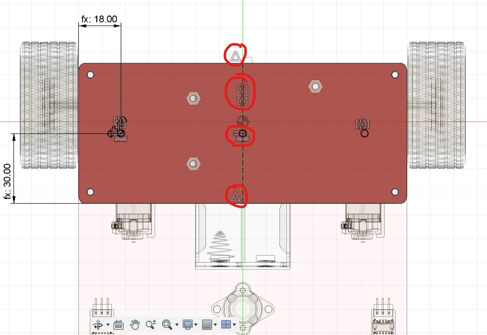
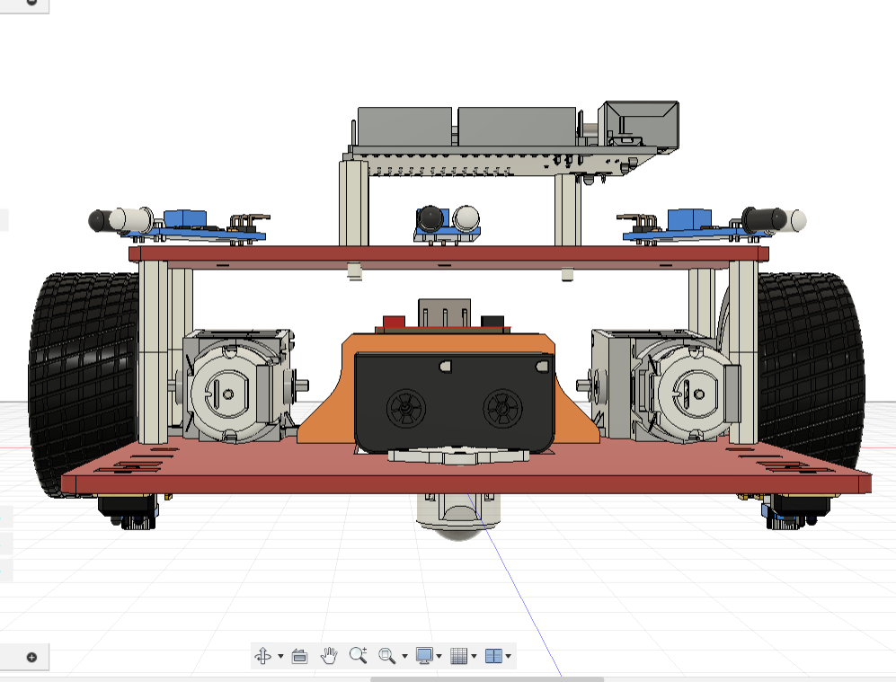
At the top level, insert three IR Sensor (FC51) components and joint them to the top plate. Point the outer sensors 45° left and right. Offset every sensor upward by 3 mm; physical assembly needs 3 mm washers so the leads are not bent.
Step 5: Front Guard and Wedge
Create the Printed Brackets
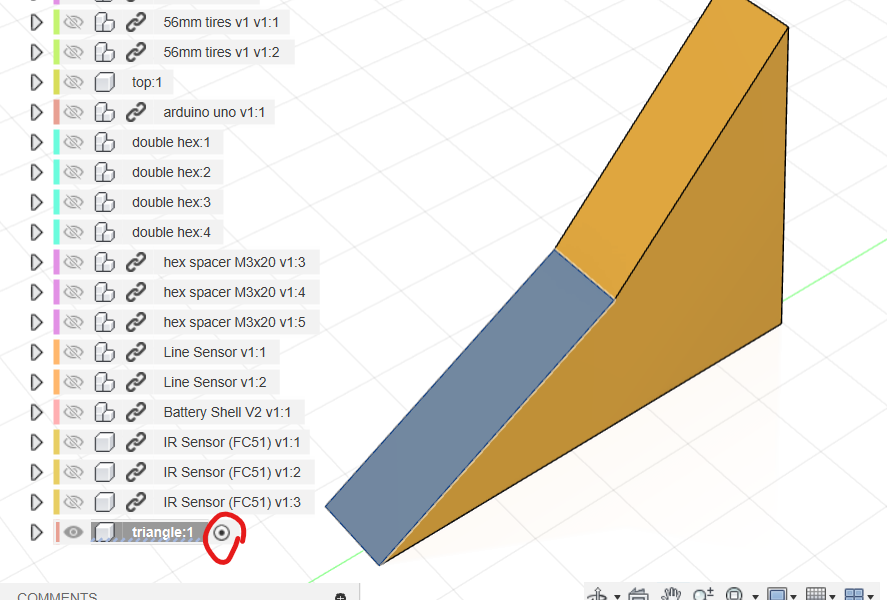
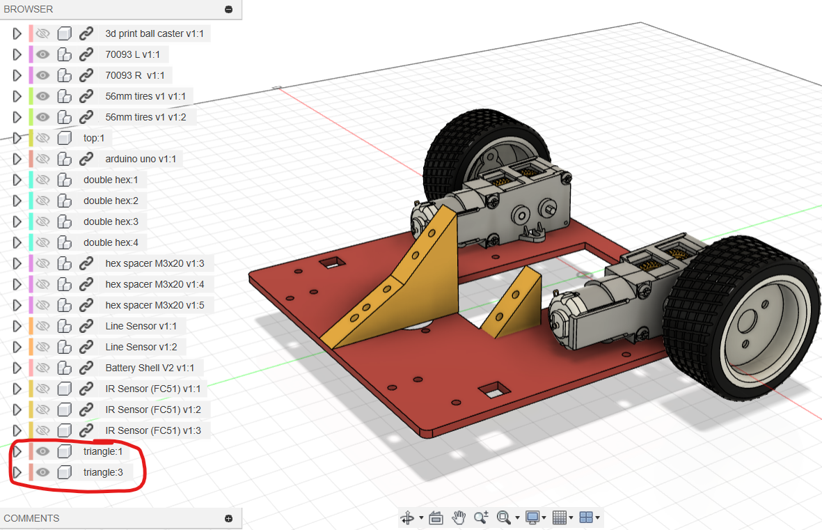
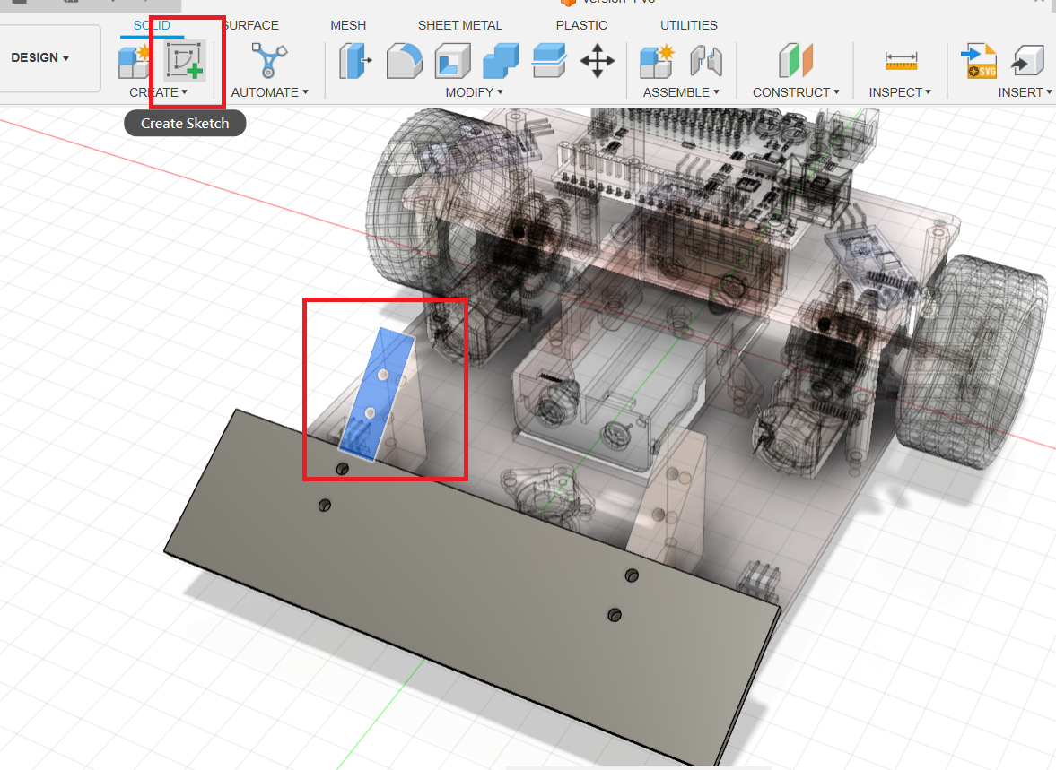
At the top level create triangle, hide everything except it and bottom, activate it and sketch on YZ.
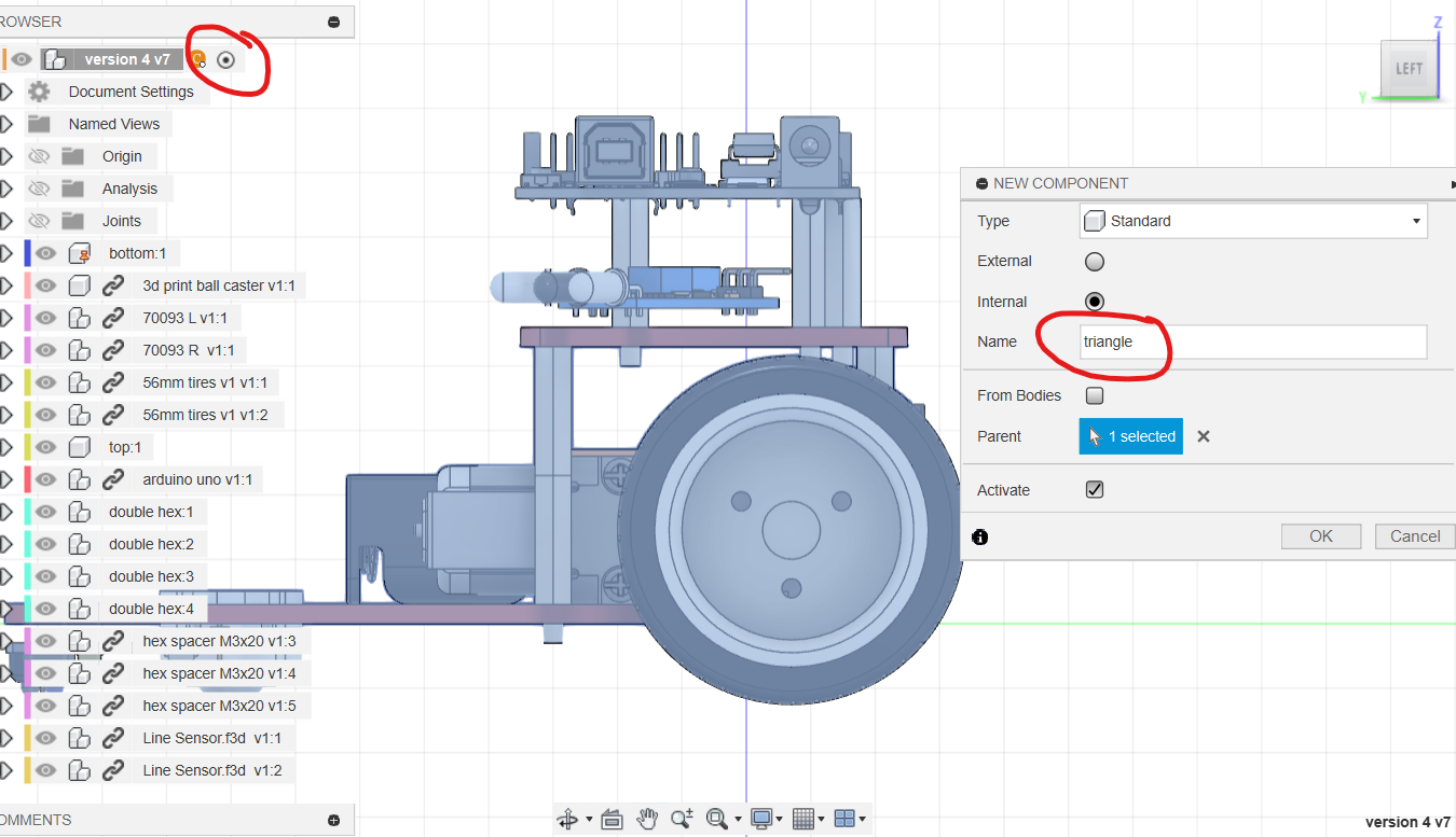
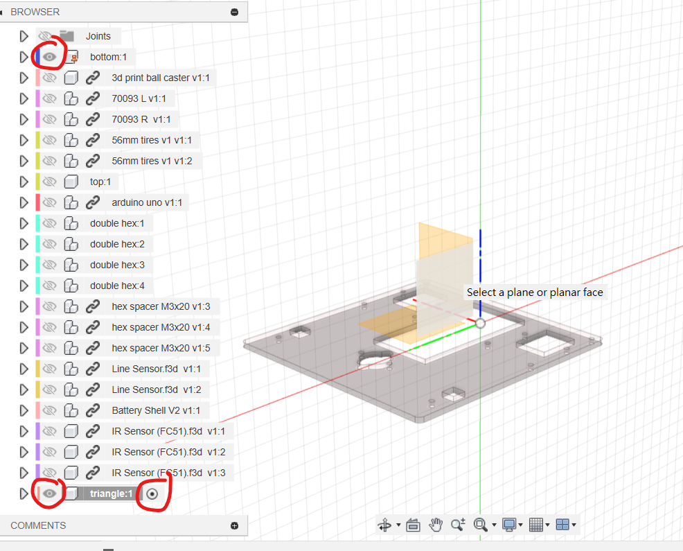
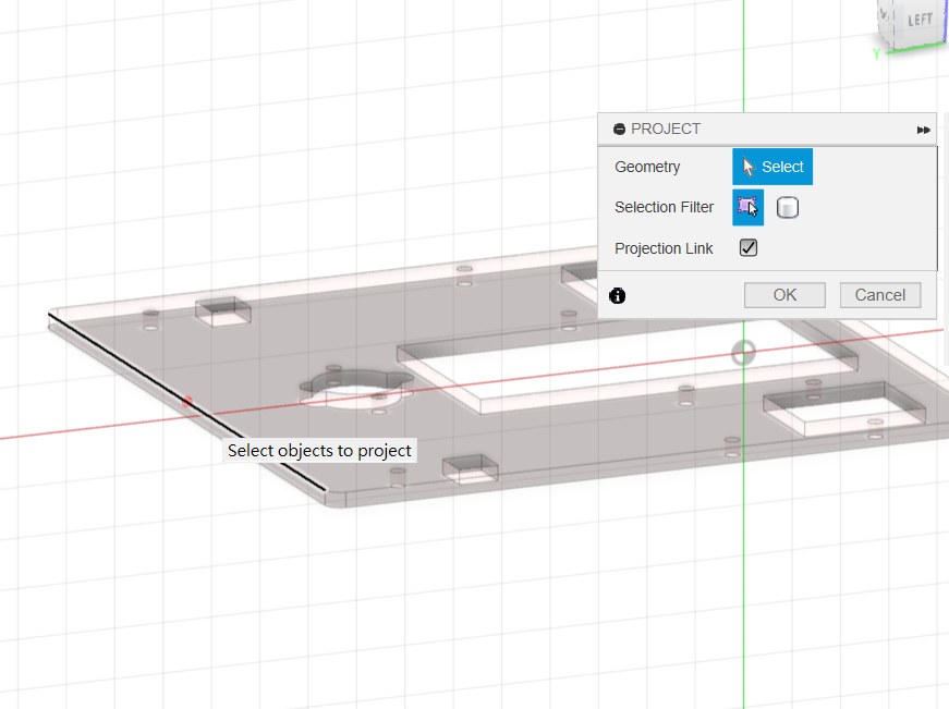
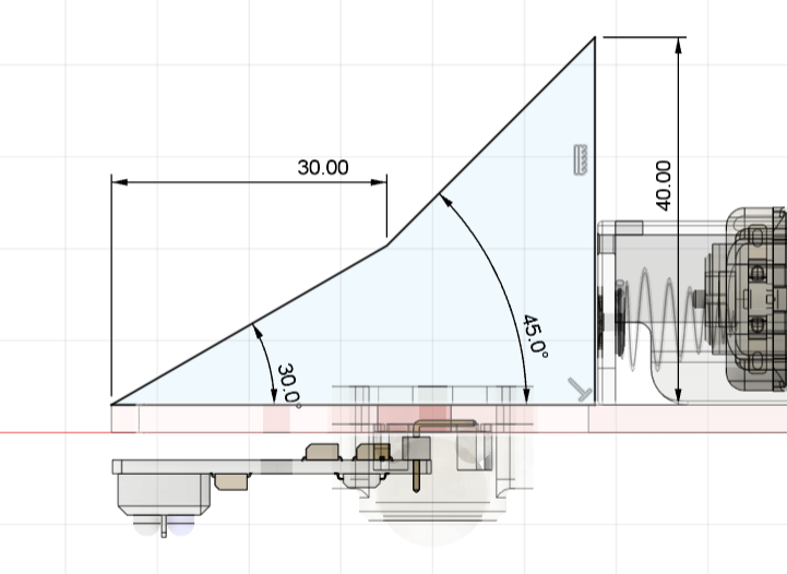
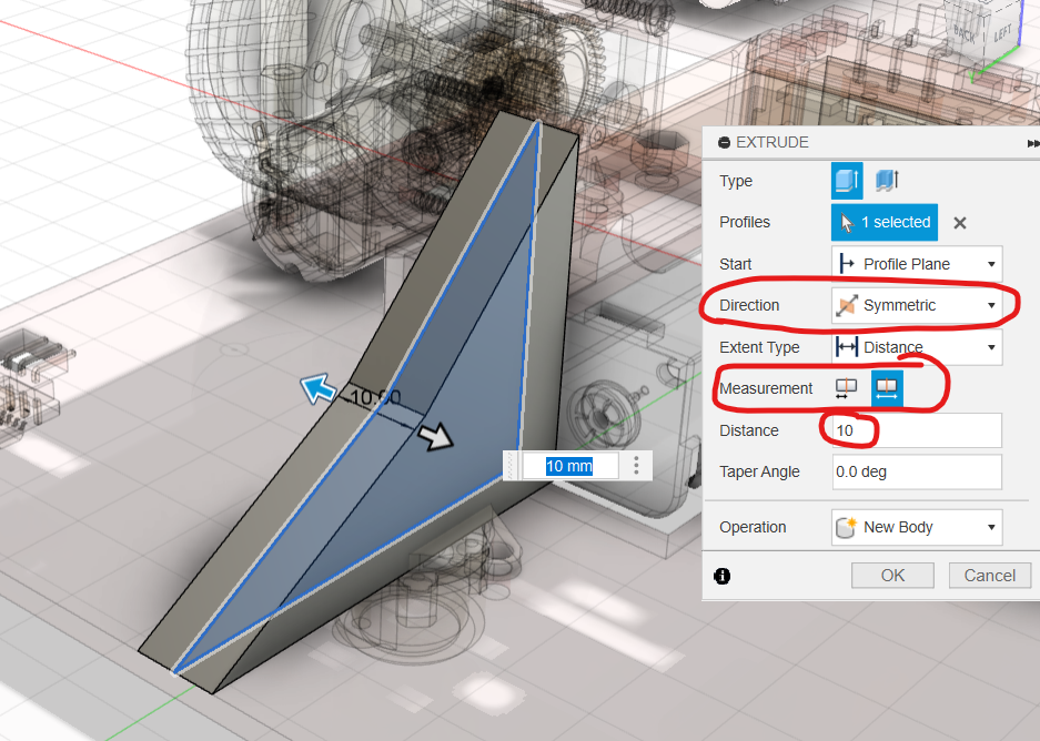
Project the top of the bottom plate and draw the bracket to the dimensions shown. Extrude symmetrically with total length 10 mm.
Sketch on the 30° face, add a centreline and two Ø3 mm holes, then cut 10 mm deep.
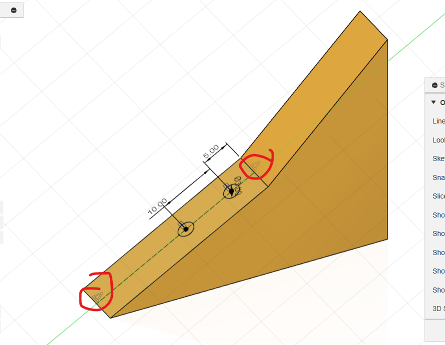
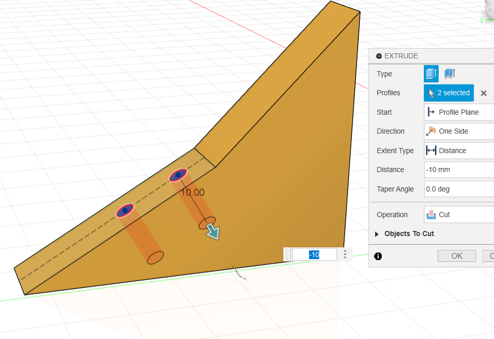
Repeat on the 45° face using the dimensions shown.
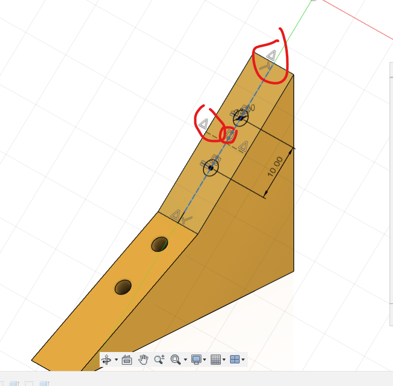
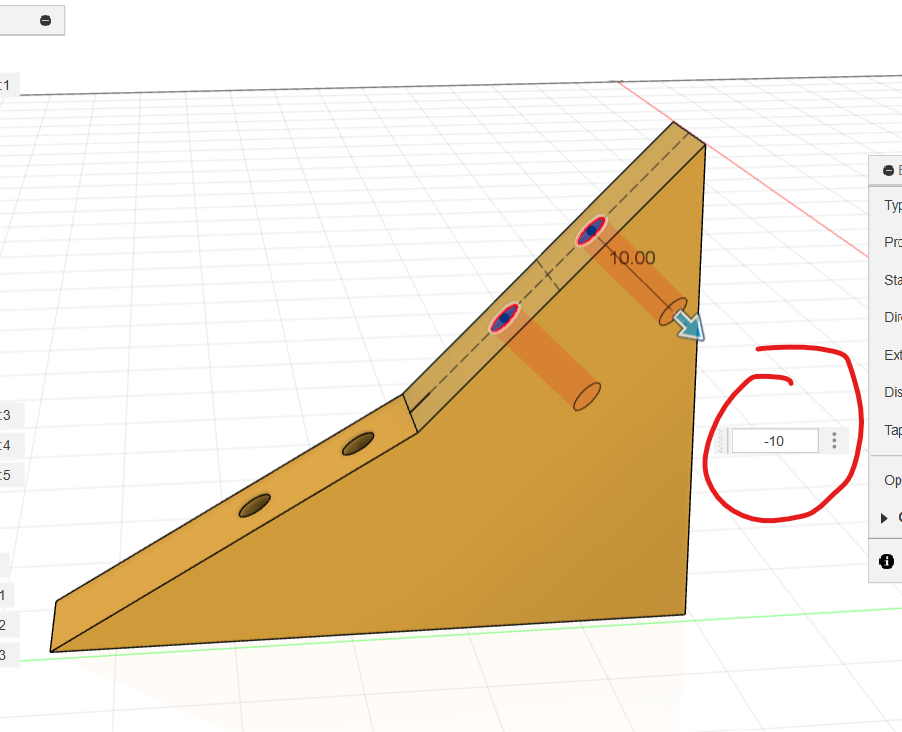
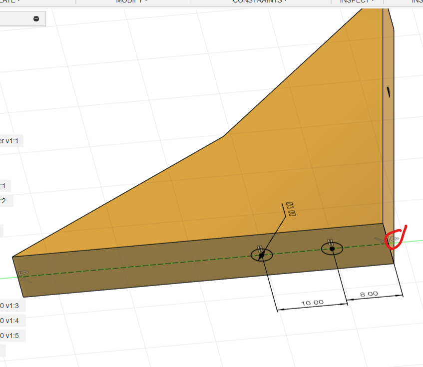
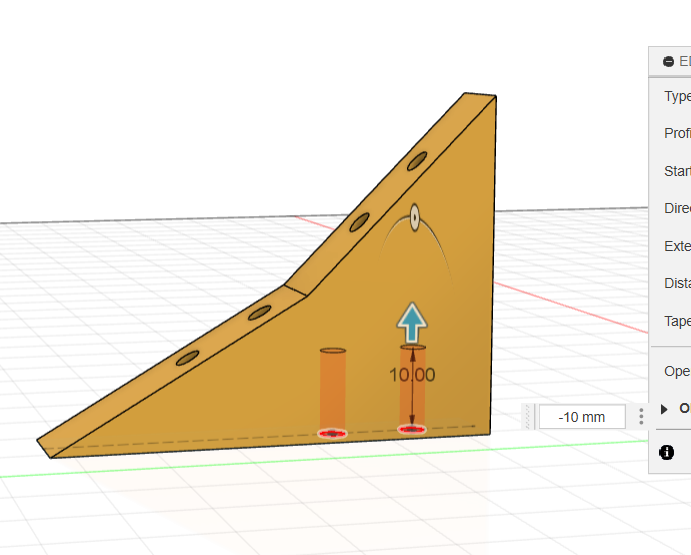
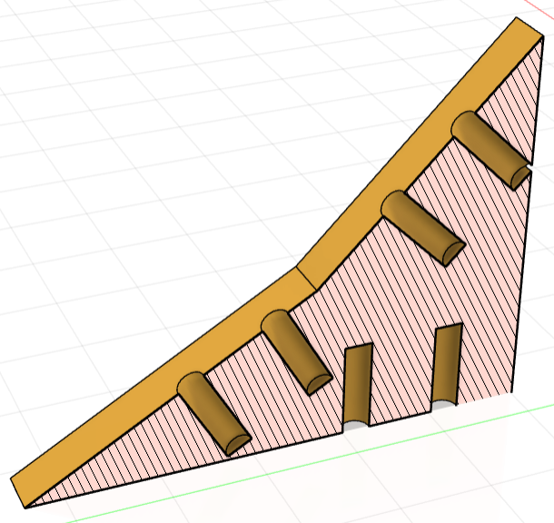
Sketch underneath and add two Ø3 mm chassis-mounting holes. Move them rearwards so they do not intersect the holes from the sloping faces.
Mount the Brackets
Show and activate bottom, then sketch on it.
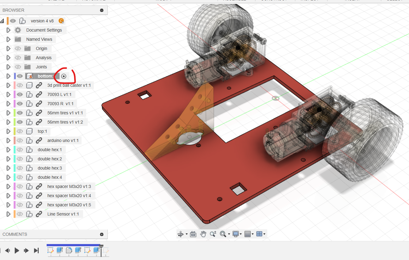
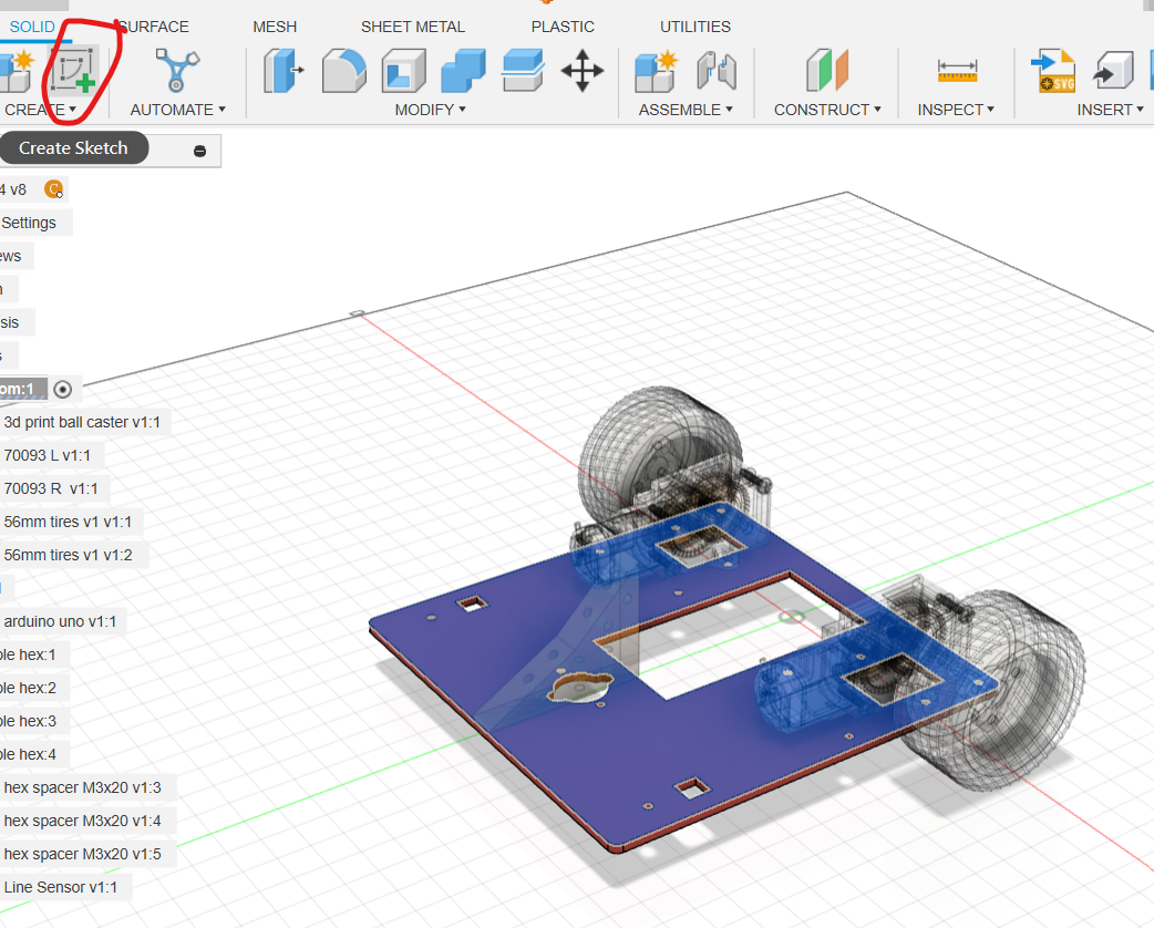
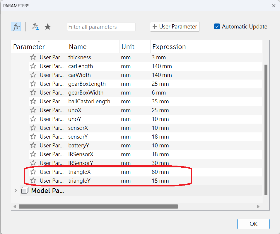
Create parameters triangleX and triangleY.
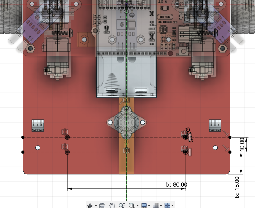
Draw a centreline and two horizontal construction lines positioned by triangleY and 10 mm. Place two Equal Ø3 mm holes aligned vertically, mirror them to the other side, and cut all four from the bottom plate.
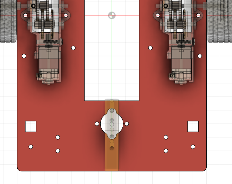
At the top level, copy the triangle and joint both brackets to the plate.
Draw the Wedge and Front Guard
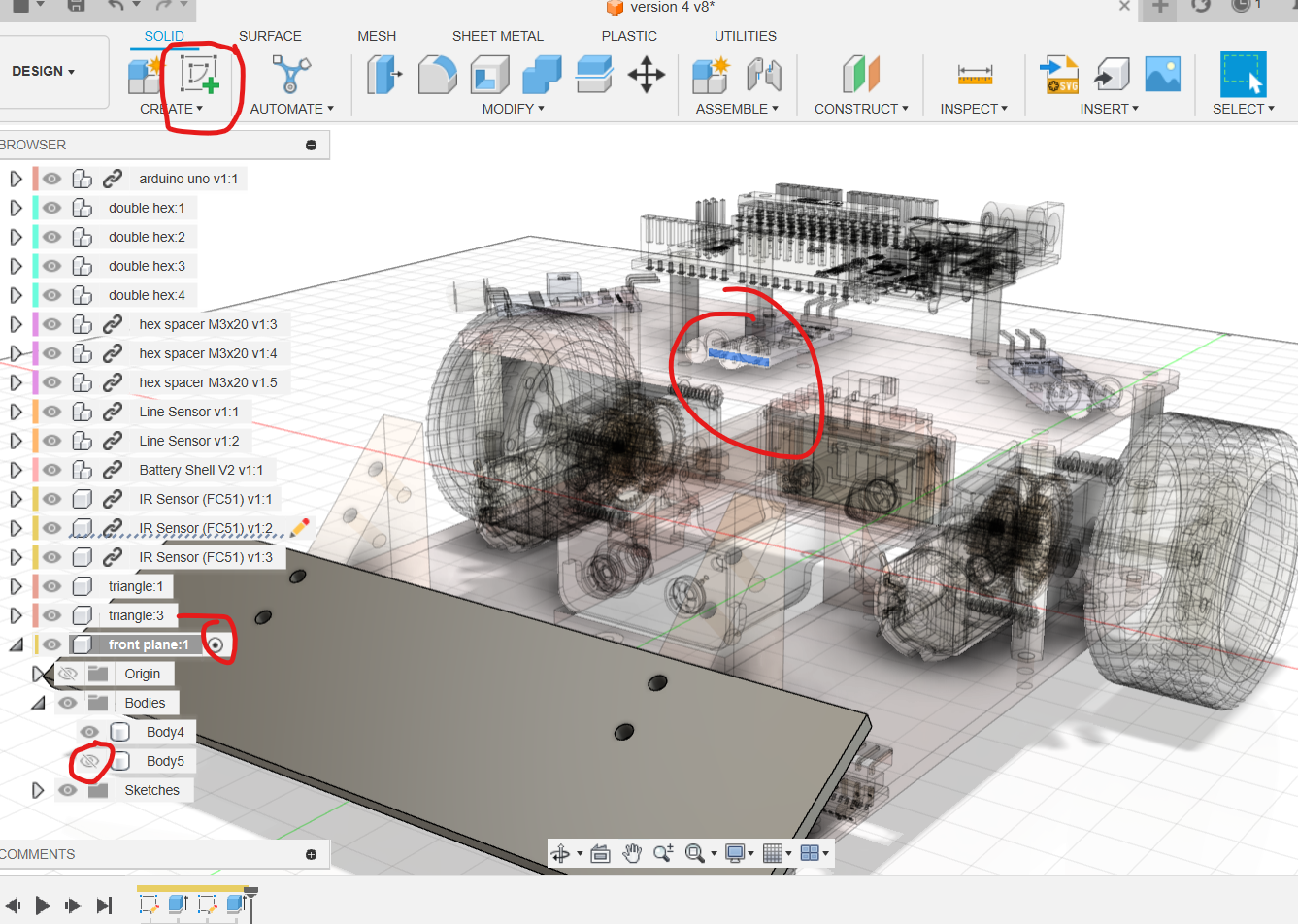
Create front plane and sketch on either bracket's 30° face.
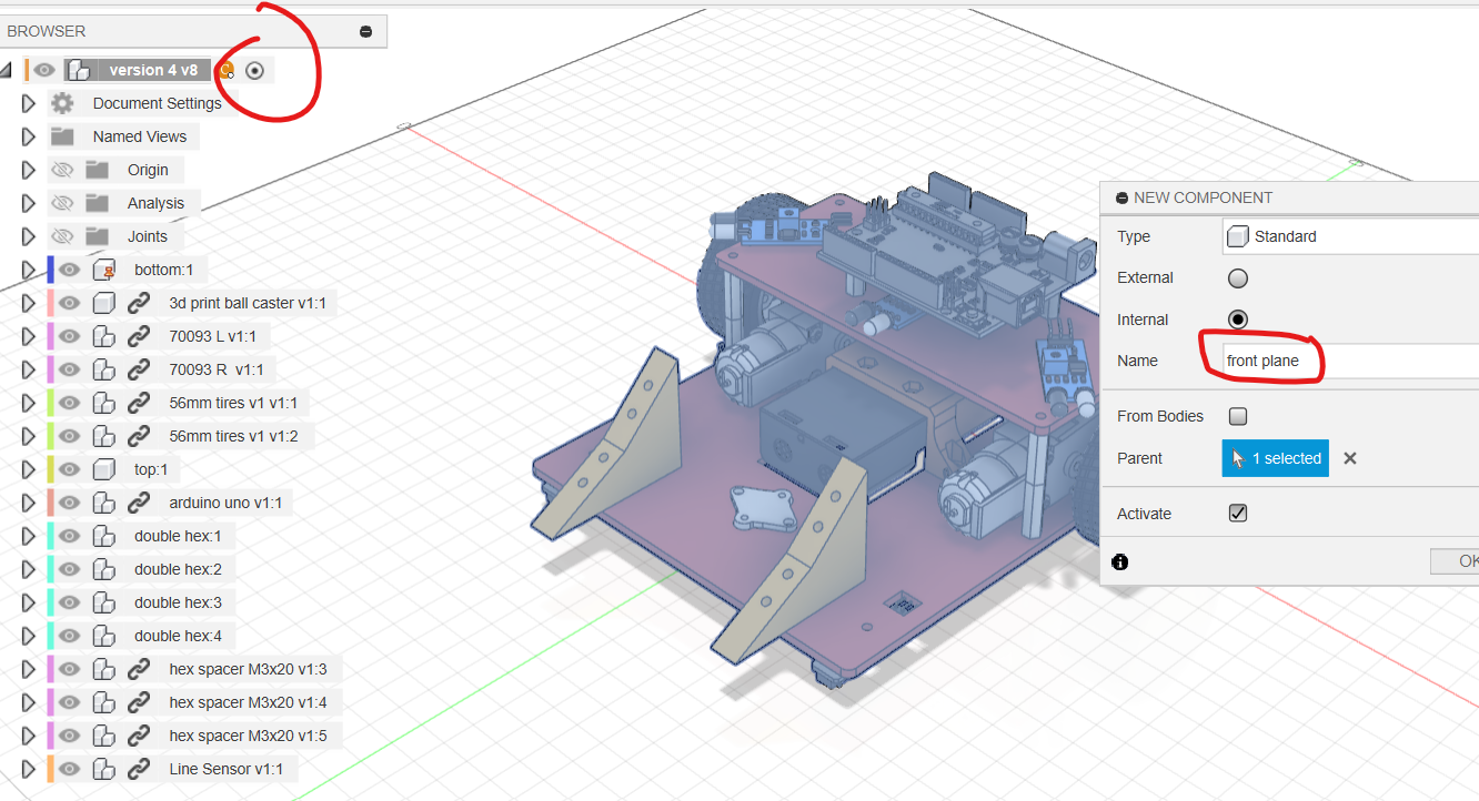
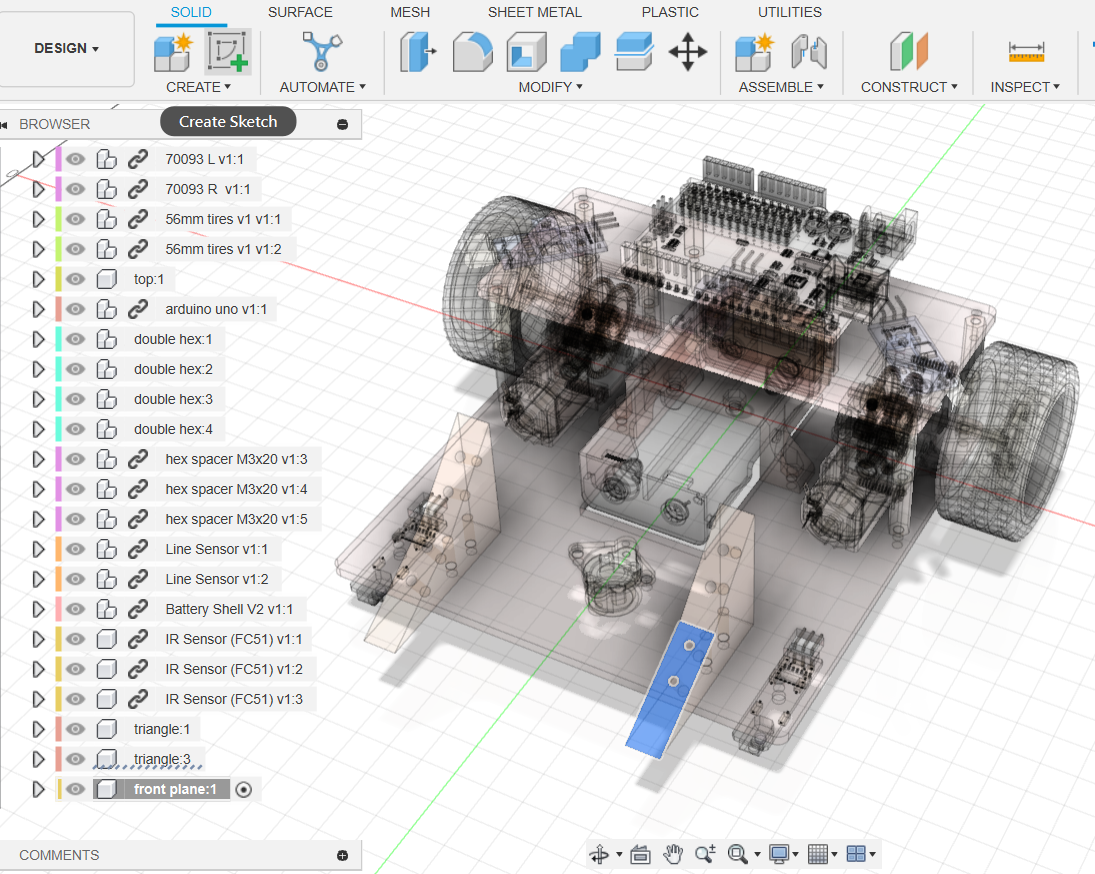
Project both brackets, draw a centreline through the origin and a rectangle whose top meets the top of the 30° faces. Extrude by thickness.
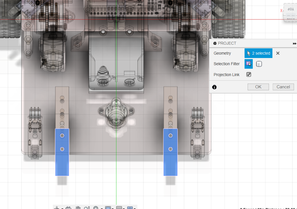
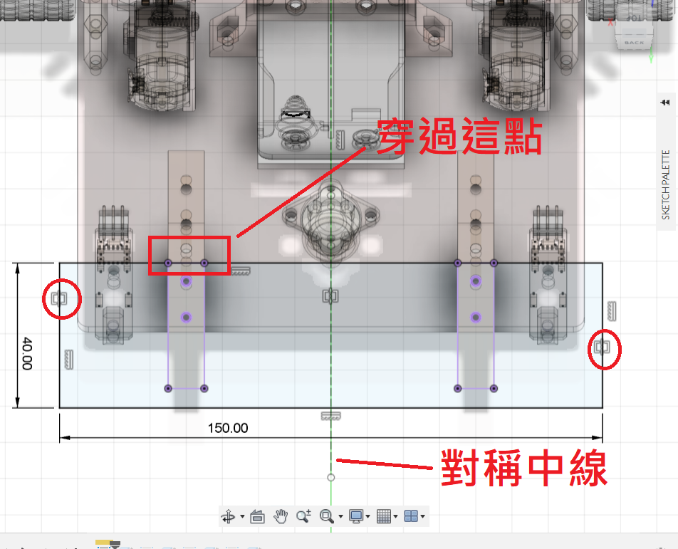
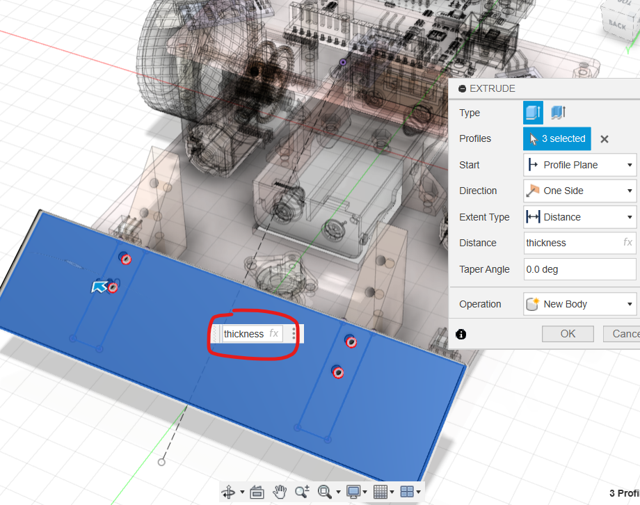
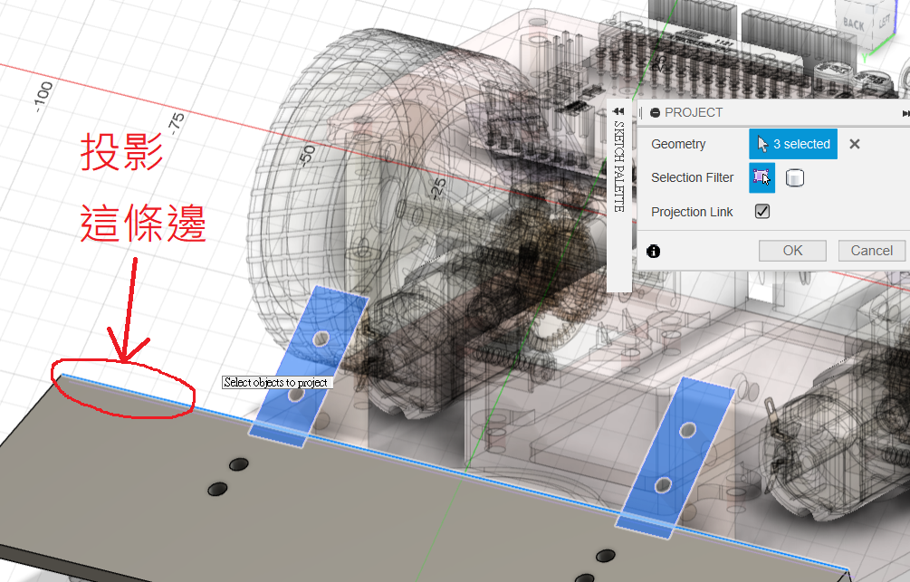
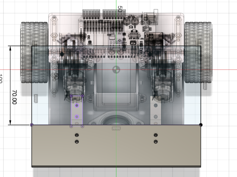
Sketch on a 45° face. Project both 45° bracket faces and the top edge of the wedge. Draw a 70 mm-wide rectangle using that projected edge and extrude by thickness. Joint the wedge/guard component to the brackets.
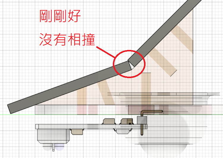
⛔️DANGER
Inspect the side view and make sure the wedge and guard bodies do not overlap or collide.
Make an Opening for the Forward IR Sensor
Activate front plane and hide the guard body. Sketch on the face of the forward IR sensor and draw a Ø15 mm circle centred between its emitter and receiver.
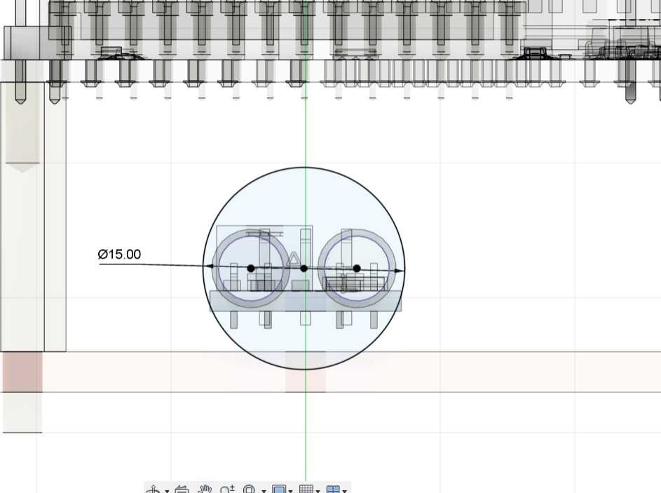
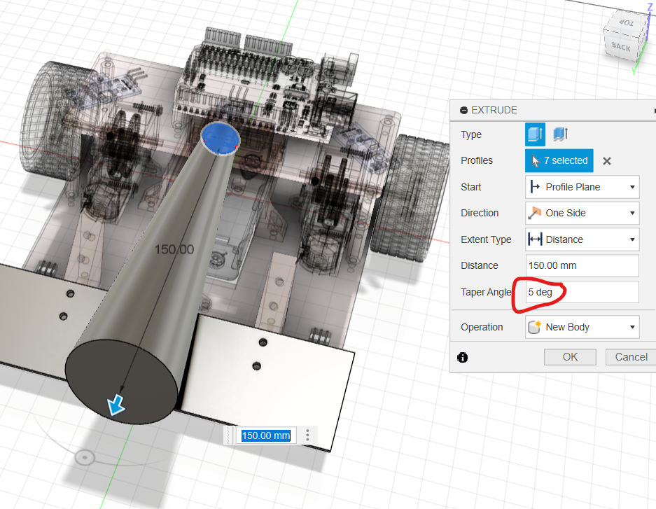
Extrude the circle as a new body farther than the chassis length, with Taper Angle = 5°. The taper approximates the sensor's field of view; choose the actual angle from sensor measurements or specifications.
Show the guard, sketch on its front face and use Intersect to obtain the section where the tapered field-of-view body crosses the guard.
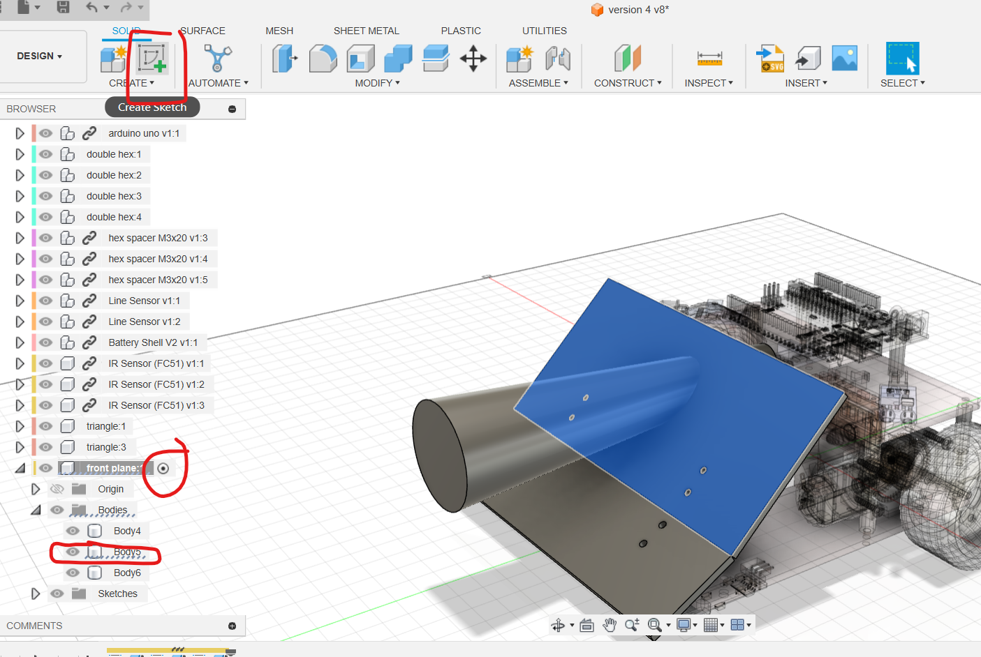
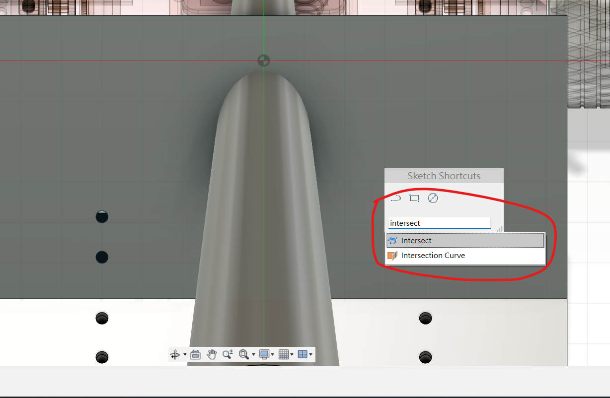
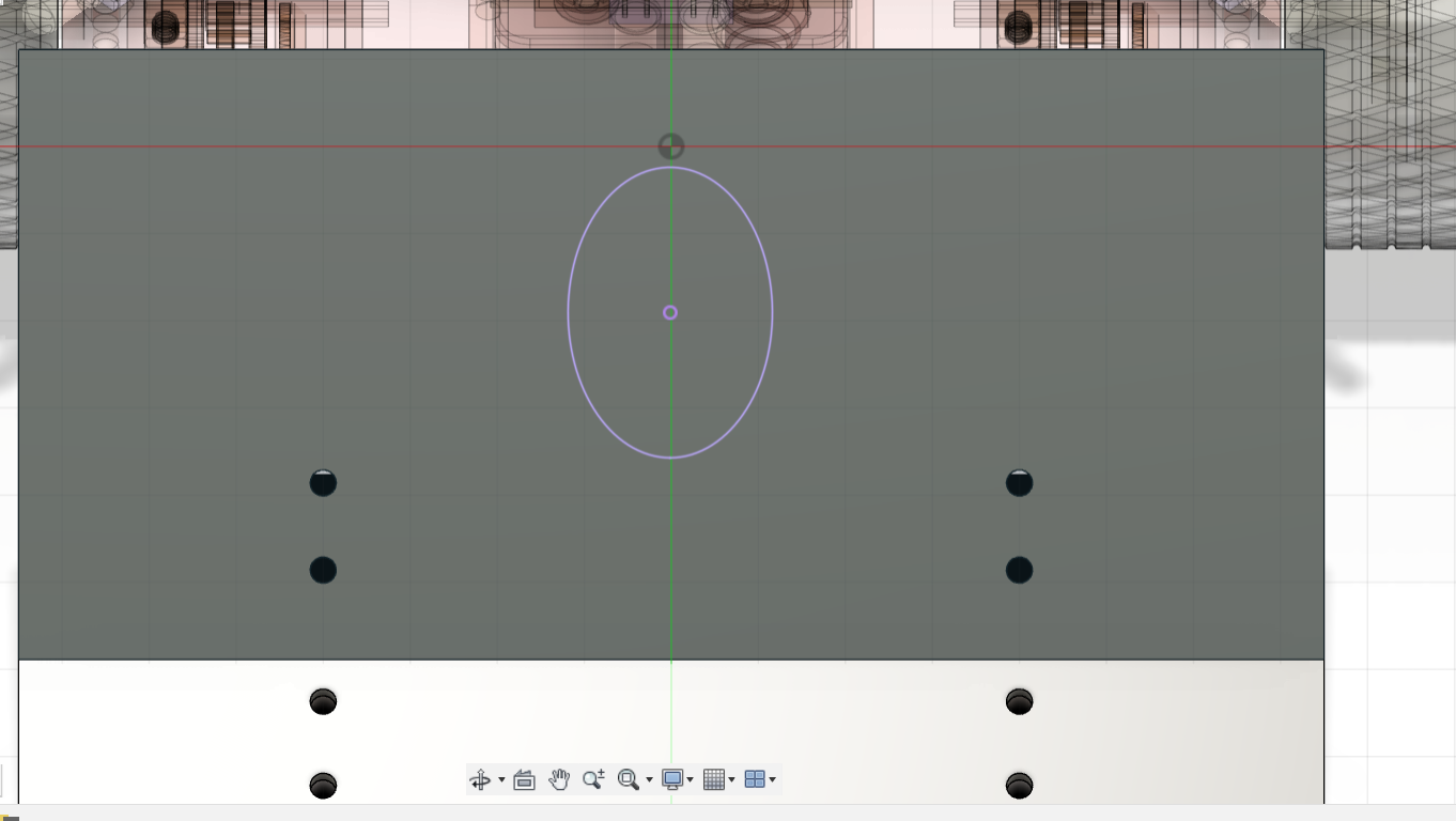
Using the ellipse centre, draw a 35 × 35 mm square and cut it through the guard so the emitted and reflected infrared path is unobstructed.
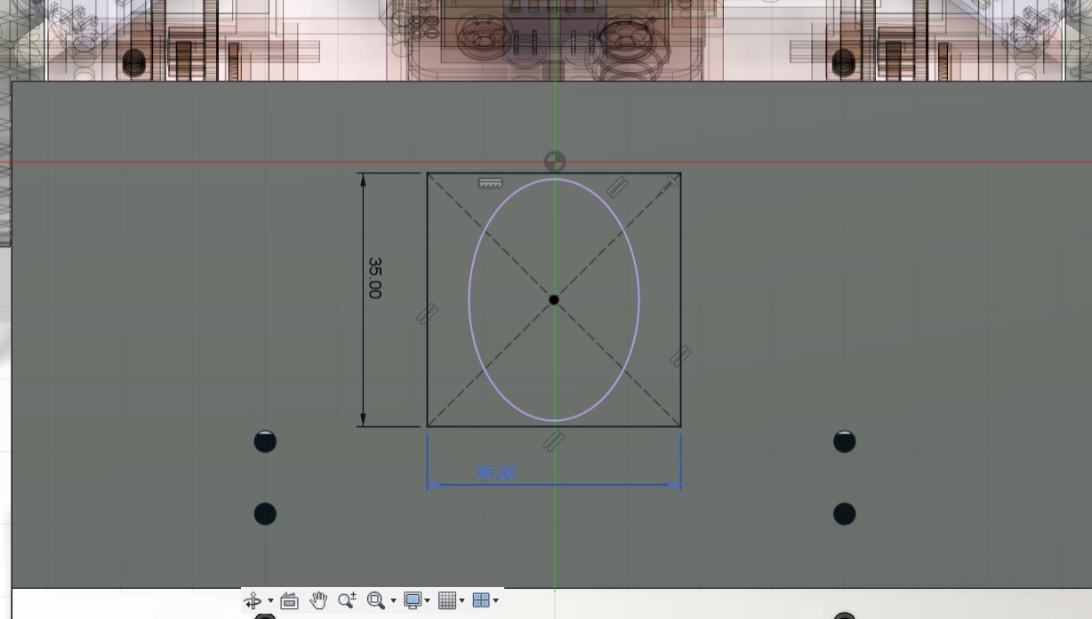
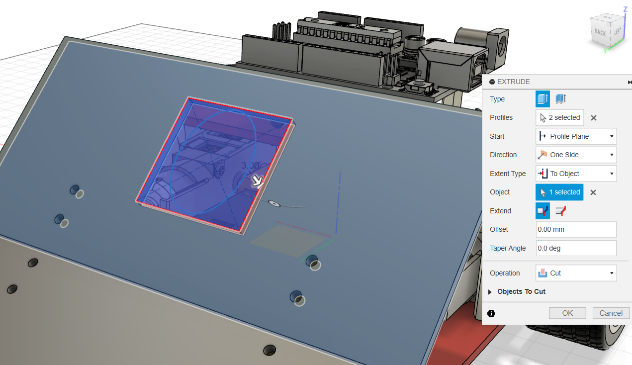
The main design is now complete. Drag each part to verify its joints and run Interference to detect physical collisions.
Step 6: Refinement Assignment
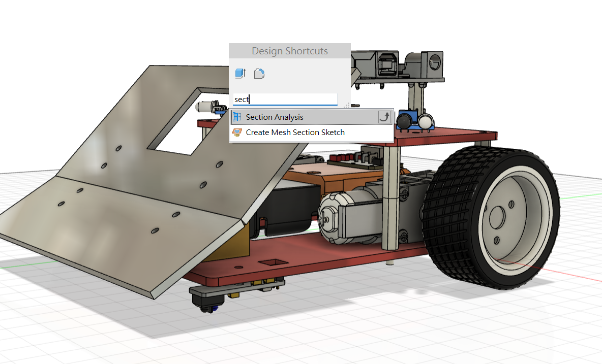
Reactivate the top level. Run Section Analysis on the world YZ plane (or the robot's side plane) to inspect the centre section.
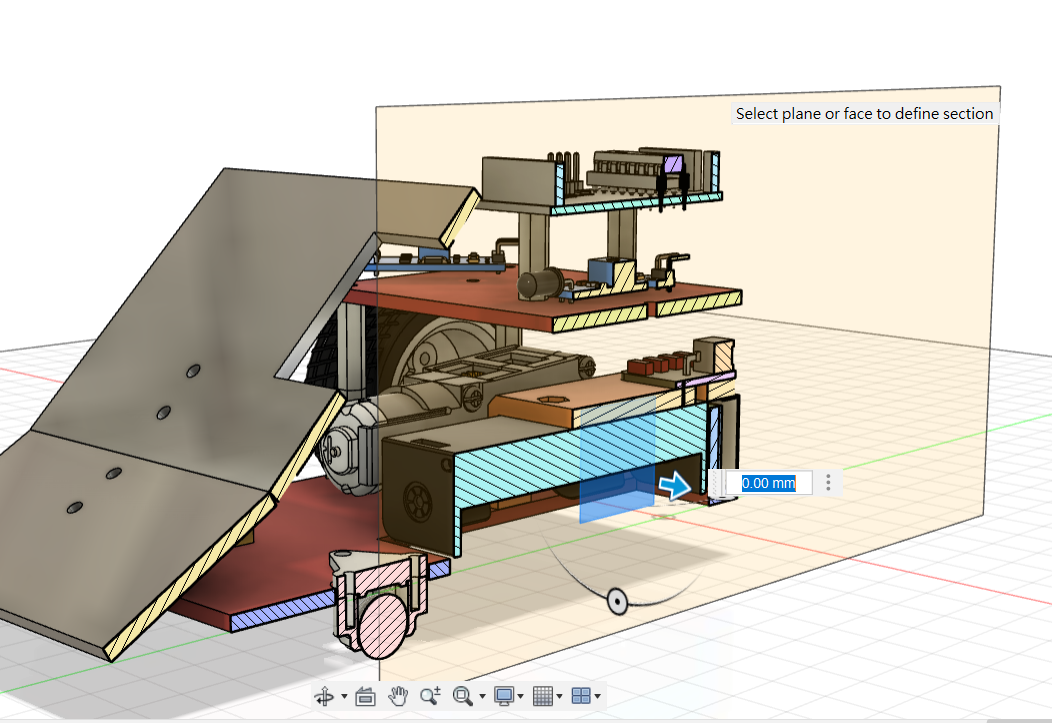
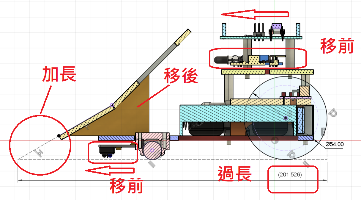
The current model has several issues to correct:
- Lengthen the 30° wedge so it reaches the floor more effectively, and add a thin metal or plastic edge closer to the ground.
- Move the downward-facing line sensors forwards so the robot detects the ring boundary earlier.
- Move the triangular brackets rearwards or shorten the chassis. Otherwise, extending the wedge makes the robot longer than the 200 mm competition limit.
- Move the opponent-detection IR sensors forwards so the front-guard opening can be smaller and opponents are detected earlier.
⛔️DANGER
Verify the applicable competition rules. A robot exceeding the permitted dimensions cannot compete.
💡TIP
The relevant positions were defined as user parameters. Edit them in Change Parameters, regenerate the model, and run Interference again before exporting manufacturing files.
Translation notice: This English page was generated automatically by AI and has not yet been reviewed by a human. It will be checked and revised page by page when time permits.