Introduction to Rhinoceros
1. Opening Rhinoceros
Find the Rhinoceros 5 (64-bit) or Rhinoceros 4 icon.
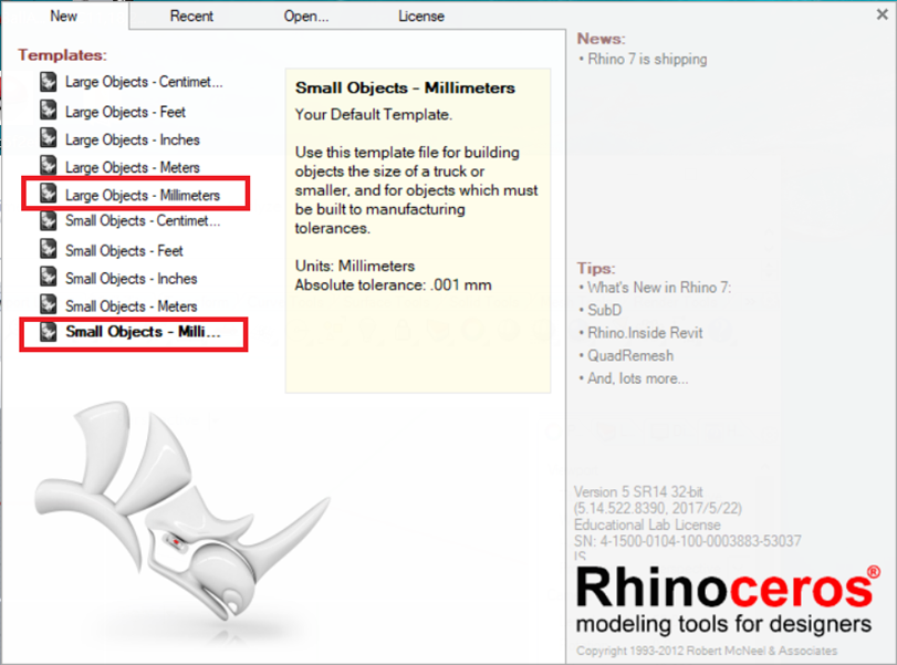
When Rhinoceros opens, choose either of these templates:
- Large Objects – Millimetres, or
- Small Objects – Millimetres.
2. User Interface
We will focus on three main parts of the interface:
- Command line
- Object Snap
- Status bar
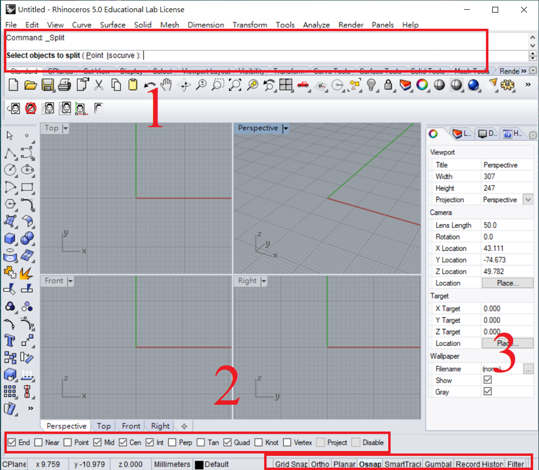
1. Command Line
- Drawing applications contain many functions spread across several menus and toolbars. A search box or command line lets users run commands directly and quickly.
2. Object Snap

- Pay particular attention to
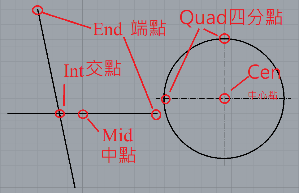
Osnap, short for Object Snap. The image above shows both its English and Chinese labels. Grid Snapis also useful when you want the cursor to lock onto grid points.

Osnaplocks the cursor onto specific geometric points, such as an endpoint, midpoint or centre.
Start Drawing
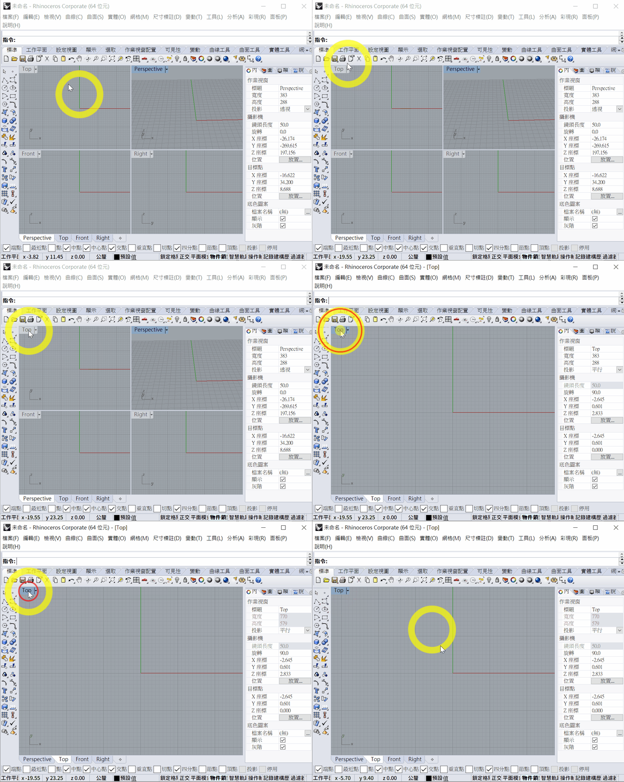
- For this exercise, use only the Top viewport. Double-click the
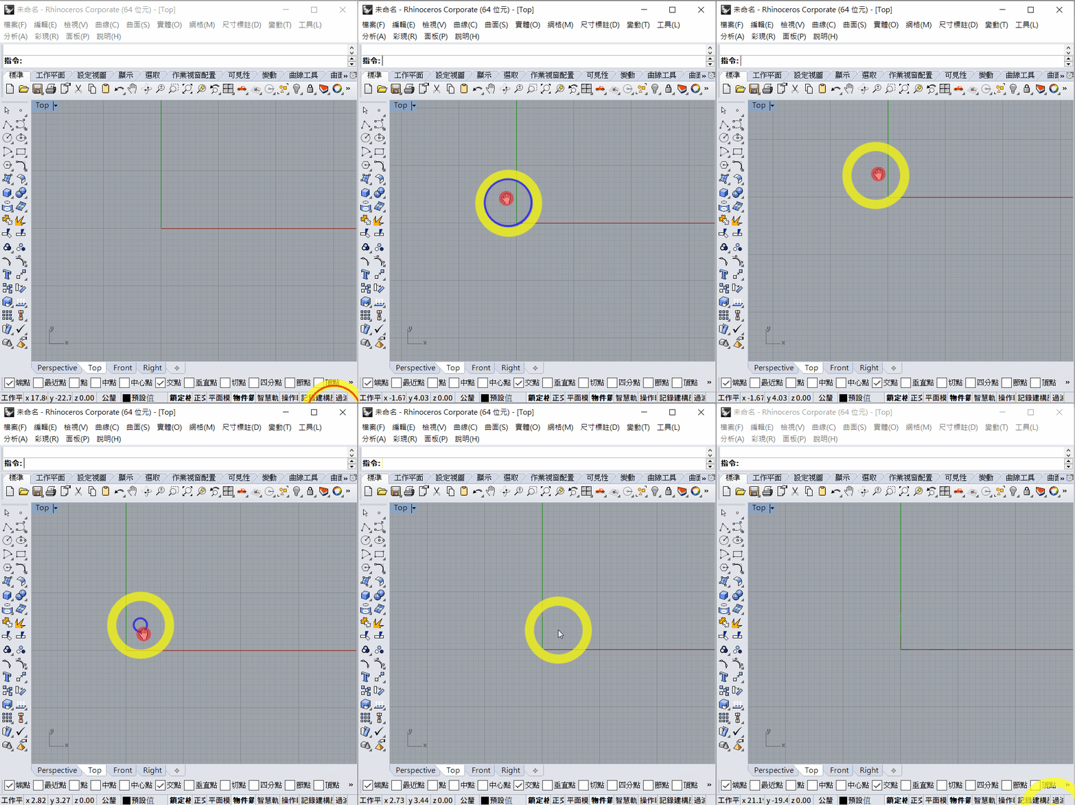
Toplabel to maximise it. - Hold the right mouse button and drag to pan the view.
1. Line and Polyline
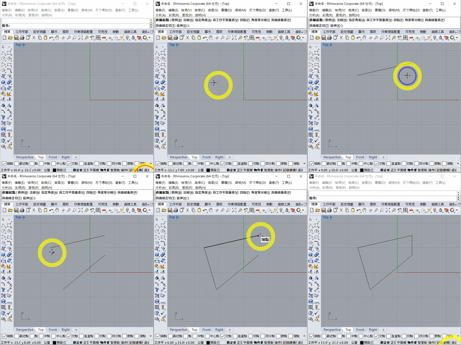
Line
- Enter the
Linecommand. - Select the starting point.
- Select the endpoint.
- To repeat the
Linecommand, right-click or press the space bar.
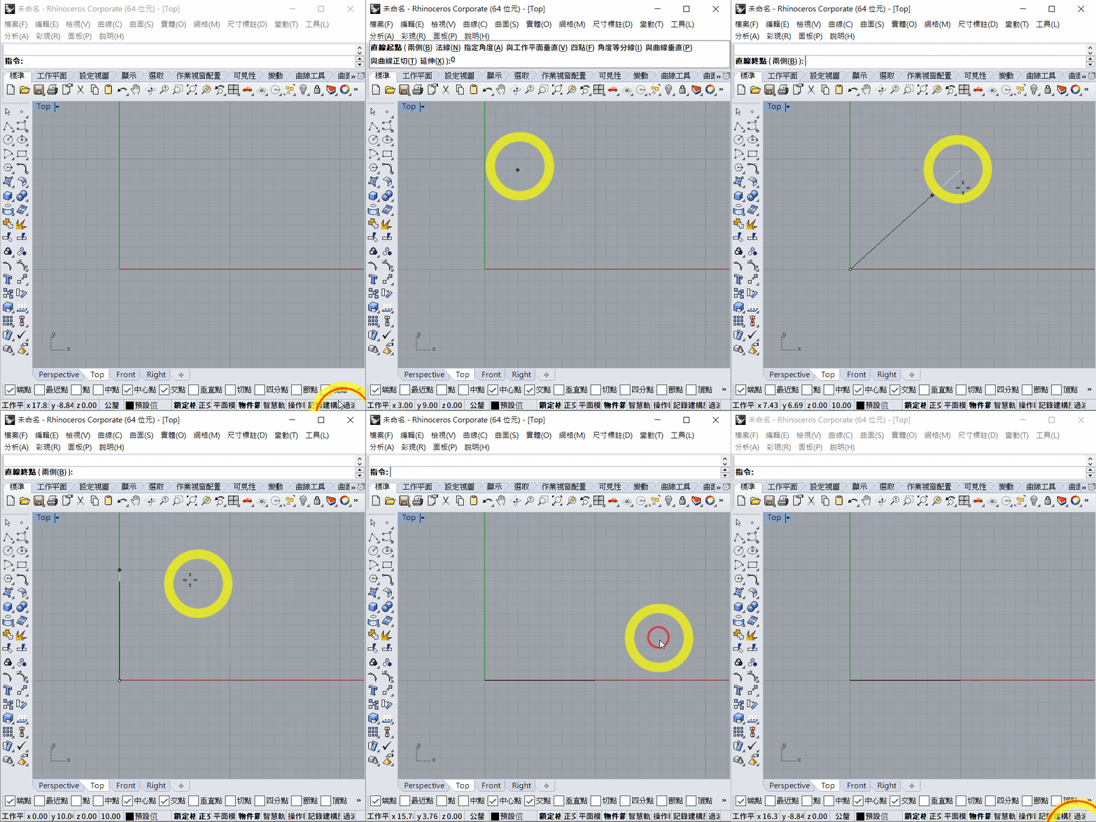
To draw a line of a specific length:
- Select the starting point.
- Enter the length—for example,
10. - A white line follows the cursor, while a black preview shows the specified 10 mm length.
- Hold
Shiftto constrain the line horizontally or vertically. - Left-click to confirm the line.
To draw a line at a specific angle and length:
- Select the starting point.
- Enter
<60and pressEnterto constrain the line to 60° from the x-axis. - Enter
10and pressEnterto set its length to 10 mm. - Left-click to confirm and finish.
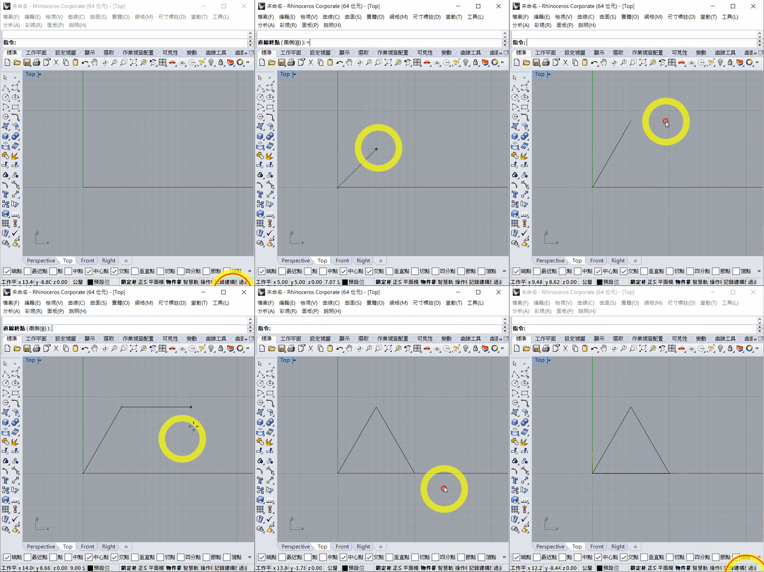
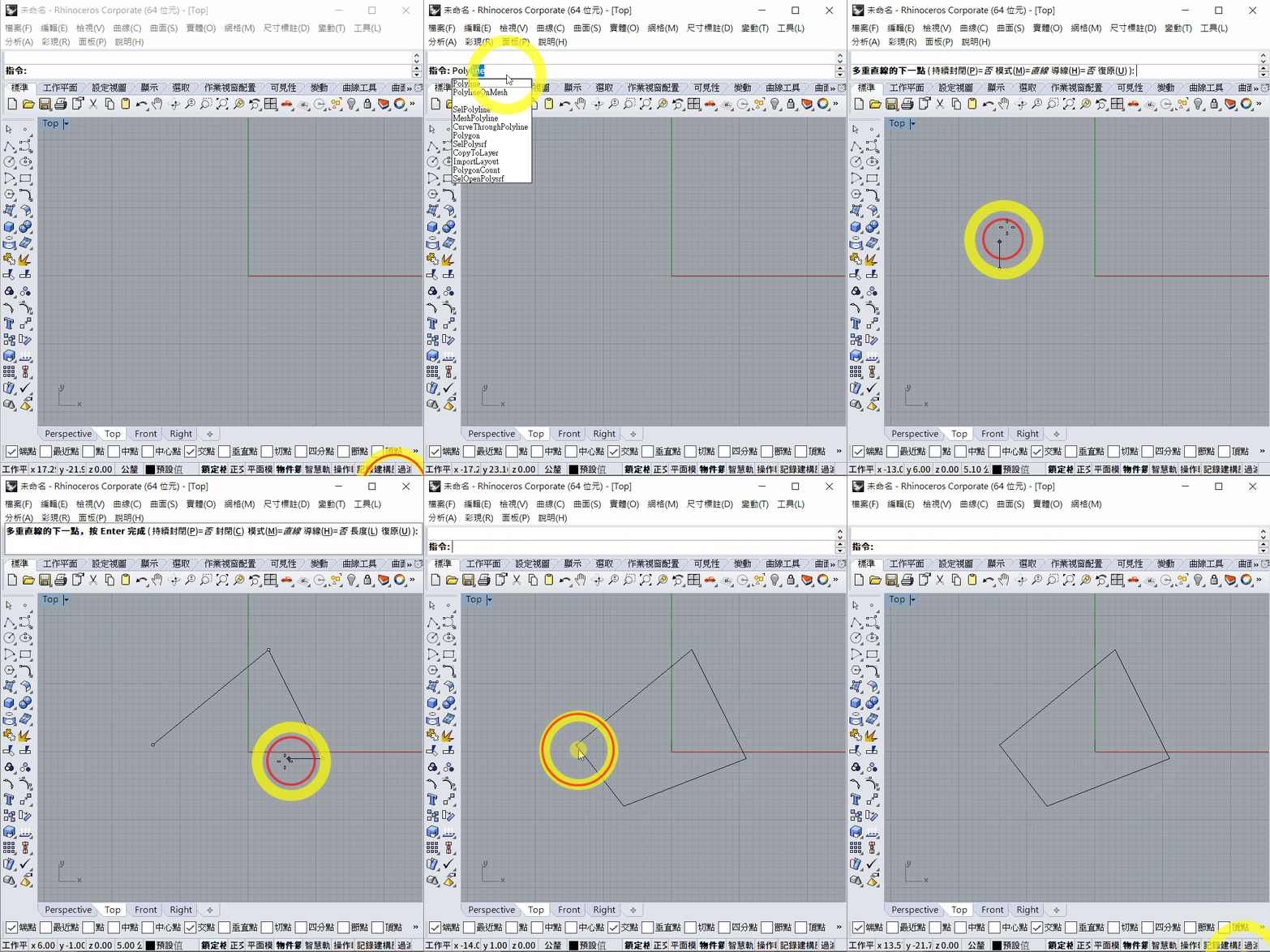
Polyline
Use the Polyline command to draw several connected line segments.
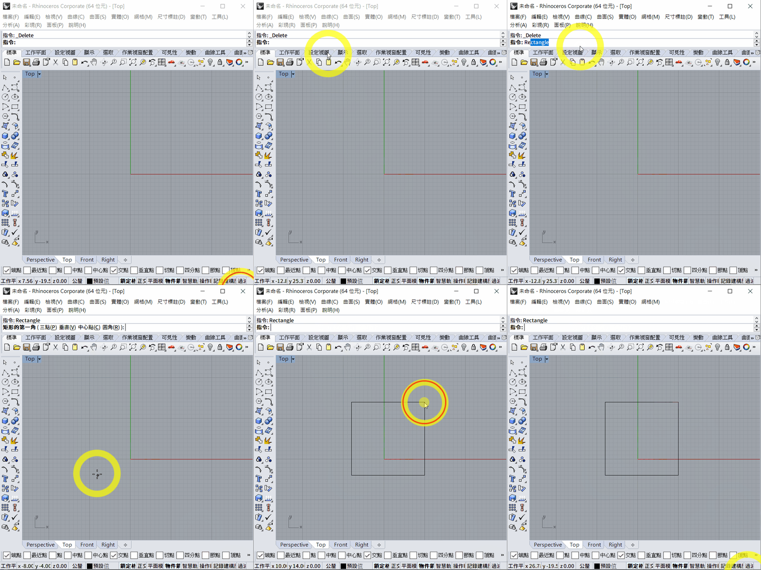
2. Rectangle
- Use the
Rectanglecommand to draw a rectangle. - There are three drawing methods.
Diagonal Mode
This is the default mode. Select two opposite corners of the rectangle.
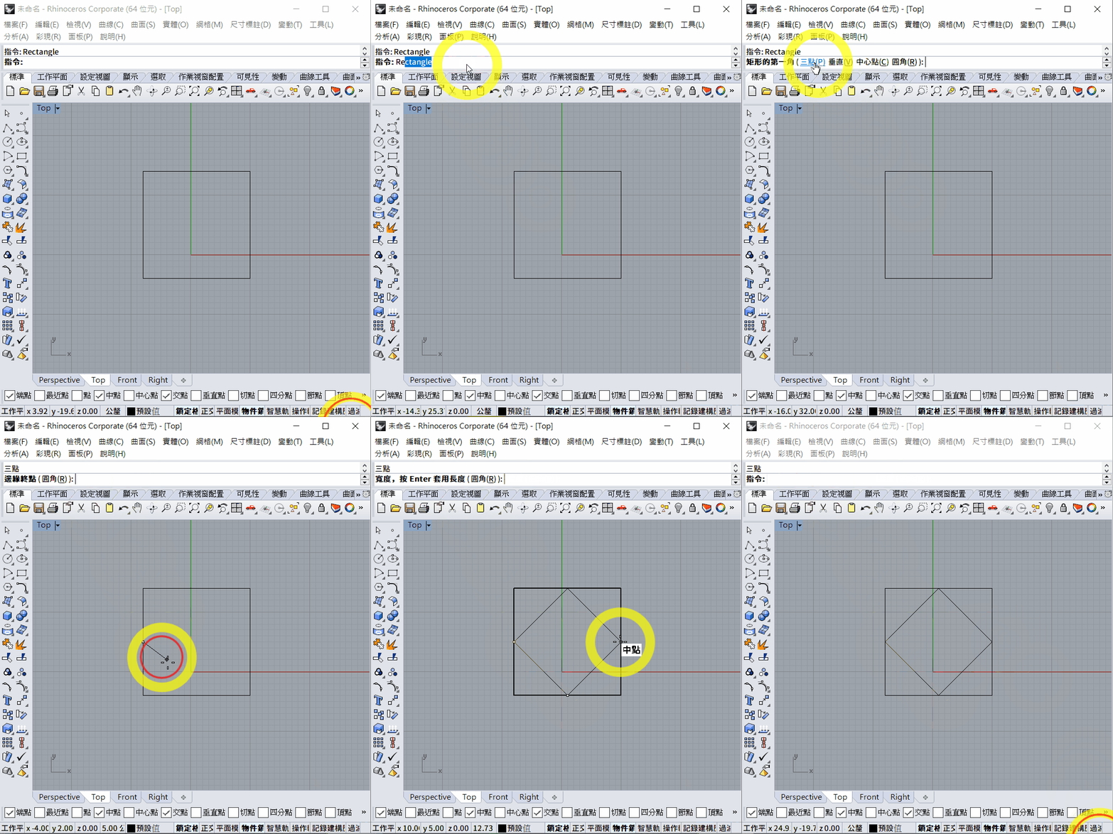
Three-Point Mode
After starting Rectangle, enter P or click 3 Point on the command line. You can then define the rectangle with three points.
Centre Mode
In Centre mode, first define the centre of the rectangle and then define a corner.
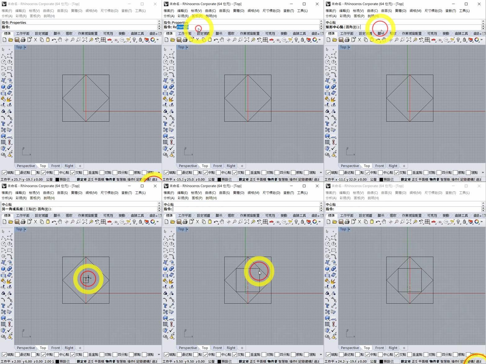
3. Circle
- Use the
Circlecommand to draw a circle. - Several drawing methods are available.
Centre Mode
This is the default mode. First select the centre, then choose R or D to define the radius or diameter.
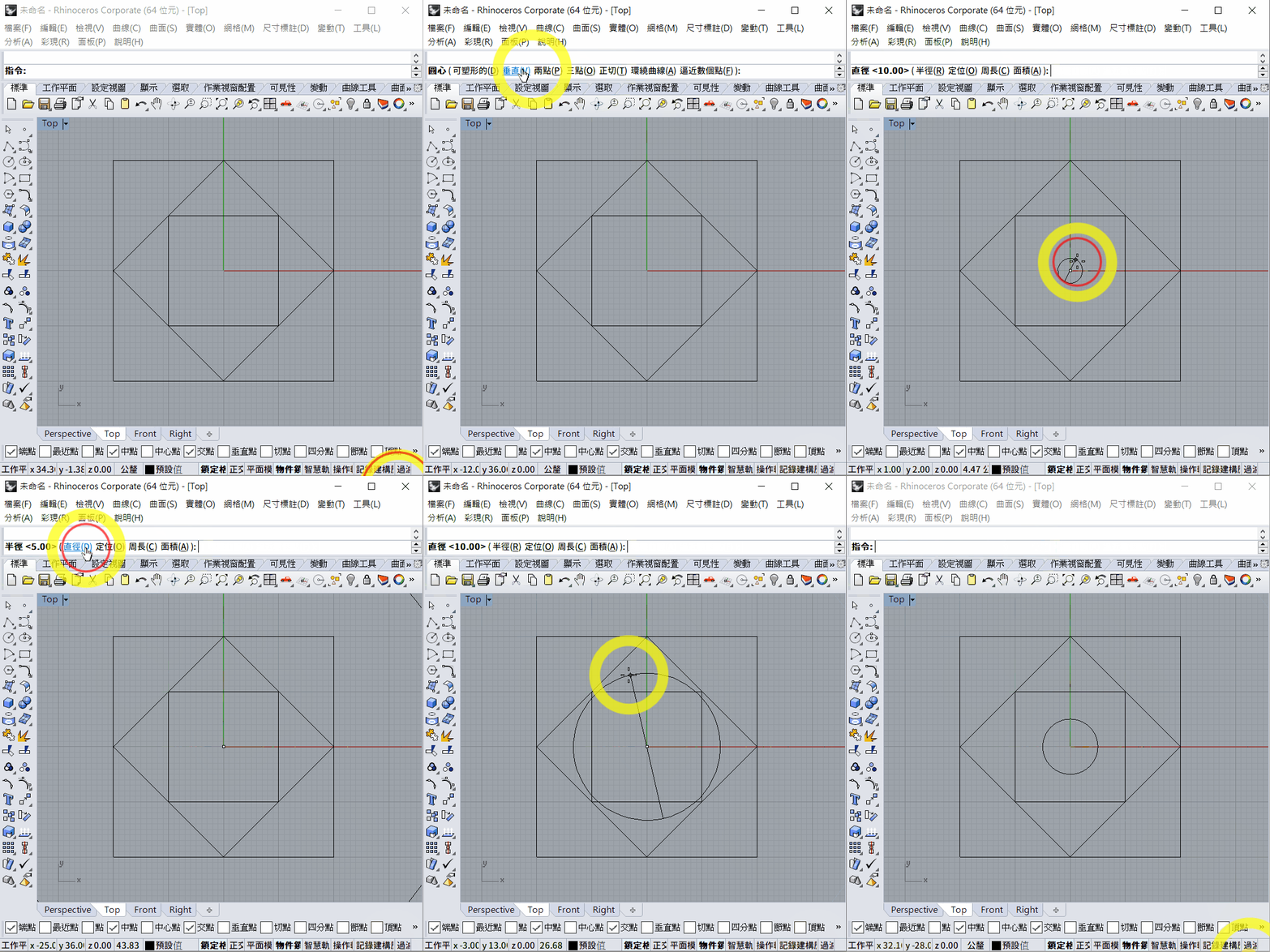
Two-Point Mode
In 2 Point mode, select two points to define the circle's diameter.
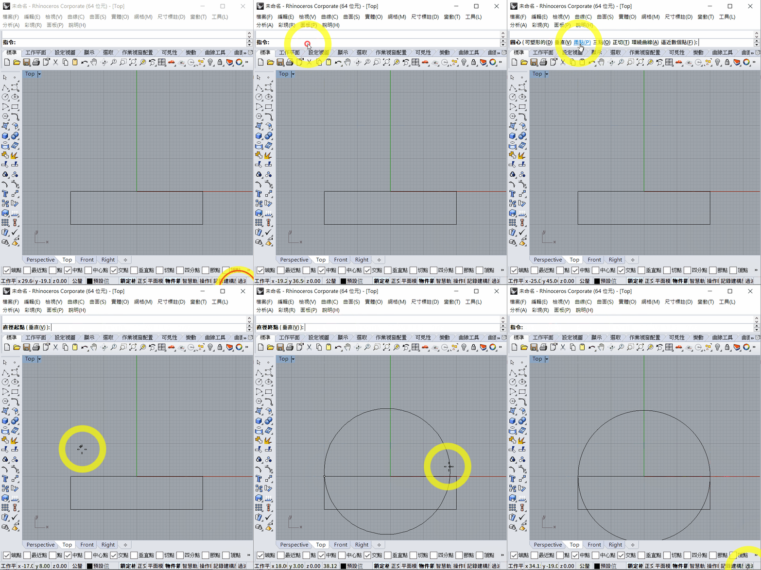
4. Trim
Use Trim to remove unwanted line segments.
- Enter the
Trimcommand. - Select the cutting objects, then press the space bar or
Enter, or right-click to confirm. - Select the segments you want to remove. Press the space bar or
Enter, or right-click when finished.
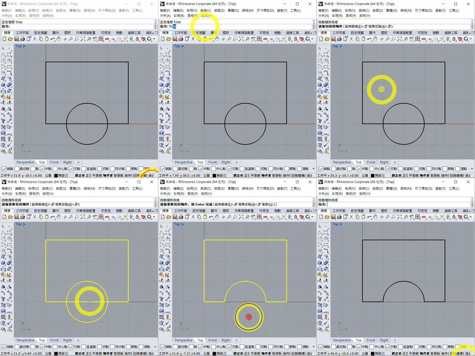
Exercise
Each grid square is 10 × 10 mm.
Download the [PDF version](week 1.pdf).

Translation notice: This English page was generated automatically by AI and has not yet been reviewed by a human. It will be checked and revised page by page when time permits.