Introduction to CNC
CNC means Computer Numerical Control: the automated control of machine tools through programmed numerical instructions. Those instructions specify how a tool moves, cuts and processes a workpiece. CNC software turns manufacturing operations into a program, which the machine uses to control position, spindle speed and feed rate accurately and repeatedly.
CNC is widely used to manufacture metal, plastic and wooden parts. It offers repeatability, productivity and the ability to produce complicated geometry. The same general idea also appears in 3D printing, laser cutting and electrical-discharge machining.
1. Manufacturing Methods
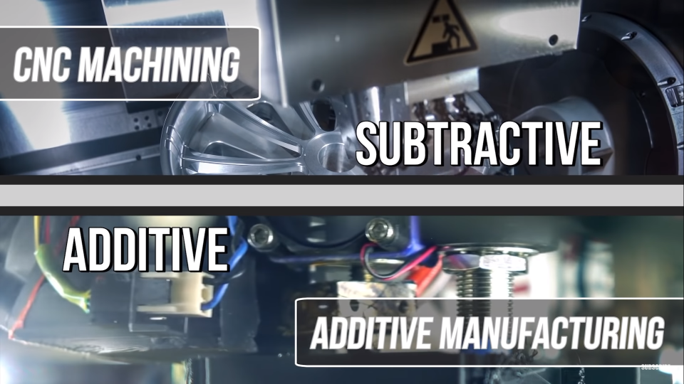
Industrial processes can broadly be divided into additive manufacturing, which builds an object by adding material layer by layer, and subtractive manufacturing, which removes material by cutting, turning or milling. Each is suitable for different jobs.
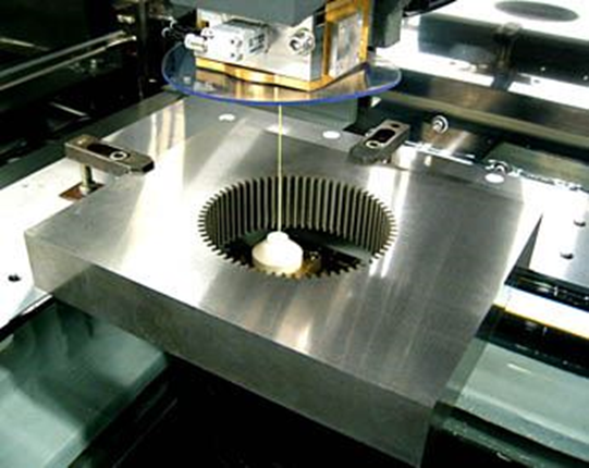
2D: Wire EDM
A CNC wire electrical-discharge machine guides a metal wire and uses electrical sparks to erode conductive material with high precision. It is common in metalworking and die manufacture, provides repeatable complex profiles and can cut very thick stock. A limitation is that the wire must enter the cutting path: an internal profile requires a starter hole, after which the wire is disconnected, threaded through the hole and reconnected.

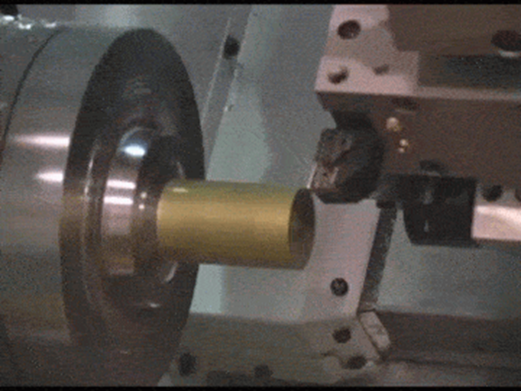
2D: CNC Lathe
A CNC lathe holds a cutting tool while the workpiece rotates at high speed. Most lathes control two main axes, normally X and Z, and are particularly suitable for shafts, bushes and disc-shaped parts. More complicated 3D geometry may require a CNC mill or machining centre.
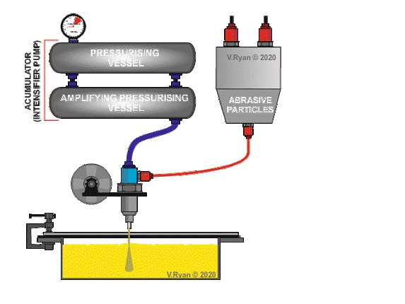
2.5D: Waterjet Cutting
Waterjet machines cut with a high-pressure stream of water, often mixed with abrasive particles. This cold process produces smooth edges with little secondary finishing and can cut metals, glass, stone, plastics and many other materials.
2.5D: Laser Cutting
Like a waterjet, a laser cutter moves a cutting head in X and Y. A focused beam can cut or engrave many materials at high speed and precision without mechanically loading the workpiece.
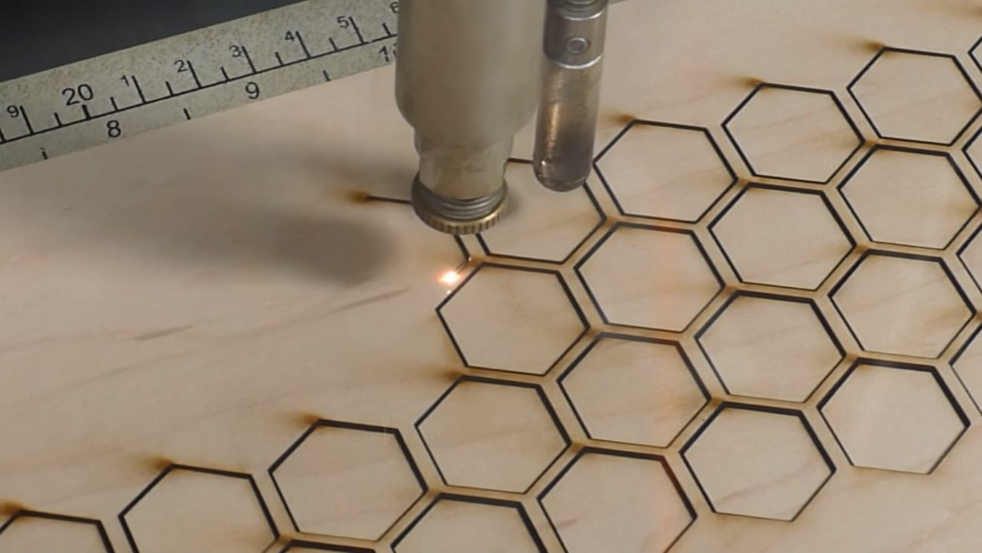
Common laser sources include:
- Glass and metal CO₂ tubes: both use carbon dioxide as the laser medium. Metal tubes generally last longer and produce better results, but cost more.
- Solid-state/diode modules: compact sources that can travel directly on the XY carriage without a mirror path. They are convenient for precise engraving, although lower-power units cannot handle every cutting application.
2.5D: Vinyl Cutter
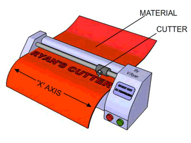
A vinyl cutter moves a small blade under computer control to cut letters and shapes from thin films such as self-adhesive vinyl. It is widely used for signs, advertising graphics and heat-transfer designs for clothing.
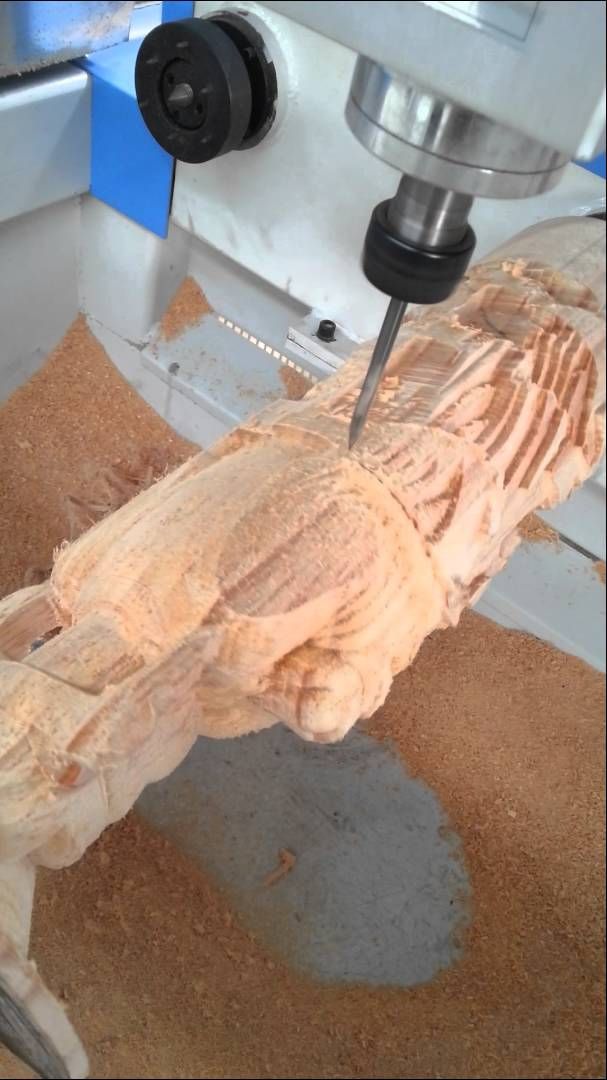
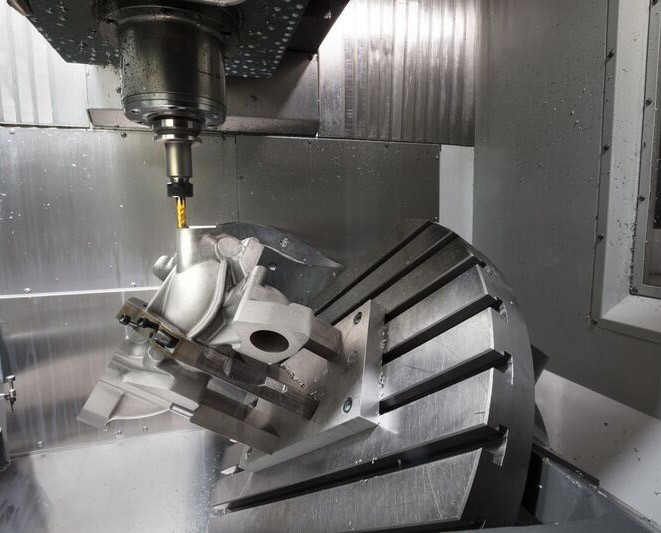
3-, 4- and 5-Axis CNC Milling
- A three-axis mill moves in X, Y and Z: left/right, forward/back and up/down.
- A four-axis mill adds a rotary axis, commonly A, allowing the part or tool to rotate during machining.
- A five-axis mill adds a second rotary axis, commonly B, providing access to highly complex surfaces and multiple sides of a part.
2. G-code
G-code, also known as RS-274, is the most widely used programming language for CNC machines and 3D printers. Commands and parameters control motion and machine functions. For example, G0/G1 specify linear movement, G2/G3 arcs, M0/M1 stops, M3 clockwise spindle or laser-on, M4 counter-clockwise spindle or laser-on, and M5 spindle/laser off. Exact commands vary among controllers.
%                  (start of program)
O0001              (program number)
T1 M06             (select tool 1 and change tool)
G90 G00 X0 Y0 Z0   (absolute coordinates; move to origin)
S1000 M03          (spindle at 1000 RPM, clockwise)
G01 Z-1 F100       (feed down 1 mm at 100 mm/min)
X20                (move to X = 20 mm)
Y20                (move to Y = 20 mm)
Z0                 (raise to Z = 0)
M05                (stop spindle)
M30                (end program)
%This program starts at , cuts at , moves to and then , and finally raises the tool to . Its XY toolpath forms an L shape.
3. Spindle Speed, Feed and Cutting Tools
3.1 Spindle Speed
Spindle speed is the cutting tool's rotational speed, normally measured in revolutions per minute (RPM). It affects the speed at which each cutting edge meets the workpiece and the cutting conditions at that contact.
3.2 Feed Rate
Feed rate is the speed at which the tool moves relative to the workpiece, normally measured in inches per minute (IPM) or millimetres per minute (mm/min).
Spindle Speed vs Feed Rate
| Setting | Advantages | Disadvantages |
|---|---|---|
| High spindle speed | More cutting-edge passes per minute; potentially faster machining | More vibration, noise and heat; may reduce accuracy or finish |
| Low spindle speed | Less vibration and noise; can improve finish | Fewer cuts per minute and slower production |
| High feed rate | Faster material removal | More force, heat and friction; may reduce tool life and finish |
| Low feed rate | Lower force and heat; may improve tool life and finish | Slower material removal |
Material Properties
Suitable values depend on both the workpiece and tool material. Hardness, strength, ductility and thermal conductivity all change the response to cutting forces and heat.
| Material | Examples | General spindle tendency | General feed tendency |
|---|---|---|---|
| Hard | Metals | Higher | Lower |
| Soft | Wood and plastics | Lower | Higher |
These are only broad classroom comparisons; real cutting data must also consider tool material, diameter, tooth count, chip load, machine rigidity and the specific workpiece.
Tool Diameter
| Tool diameter | General spindle tendency | General feed tendency |
|---|---|---|
| Small | Higher | Lower |
| Large | Lower | Higher |
3.3 Milling Cutters
Flute Count
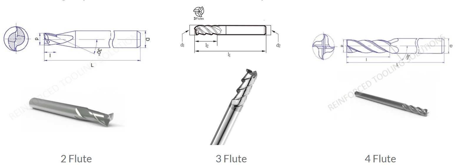
The number and design of flutes affect the materials and cutting conditions a tool can handle. Two-, three- and four-flute cutters are common. Fewer flutes provide larger chip spaces and better chip evacuation; more flutes can improve surface finish but leave less room for chips.
Ball-End and Flat-End Mills
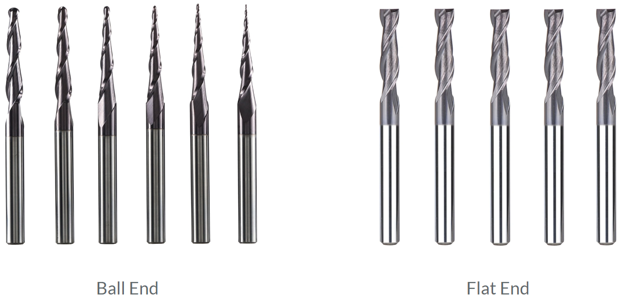
A ball-end mill has a hemispherical tip and is useful for moulds and 3D surface contours. A flat-end mill has a flat cutting end and is suitable for slots, pockets and flat-bottomed features. Choose according to the required geometry and finish.
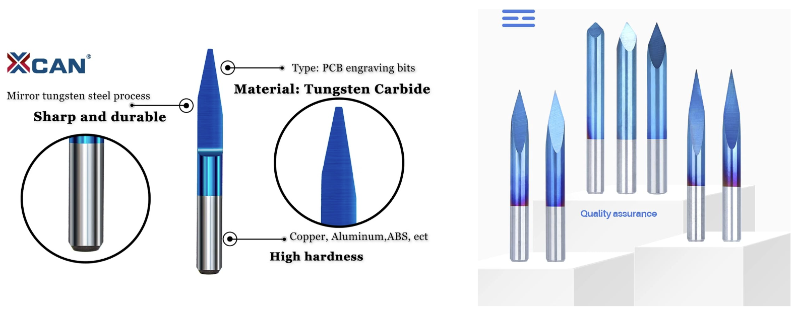
Engraving Cutters
Select engraving tools according to the material and detail required:
- Common included angles include 30°, 45° and 60°.
- Typical engraving-tool diameters range from about 0.2 to 3 mm.
- A flat-tip V-bit may have a tip around 0.1 mm for fine detail.
3.4 Surface Finish and Dimensional Accuracy
Important influences include:
- Feed and spindle speed: determine chip load and heat. Incorrectly high values can increase roughness.
- Tool wear: a worn edge worsens finish and dimensional accuracy.
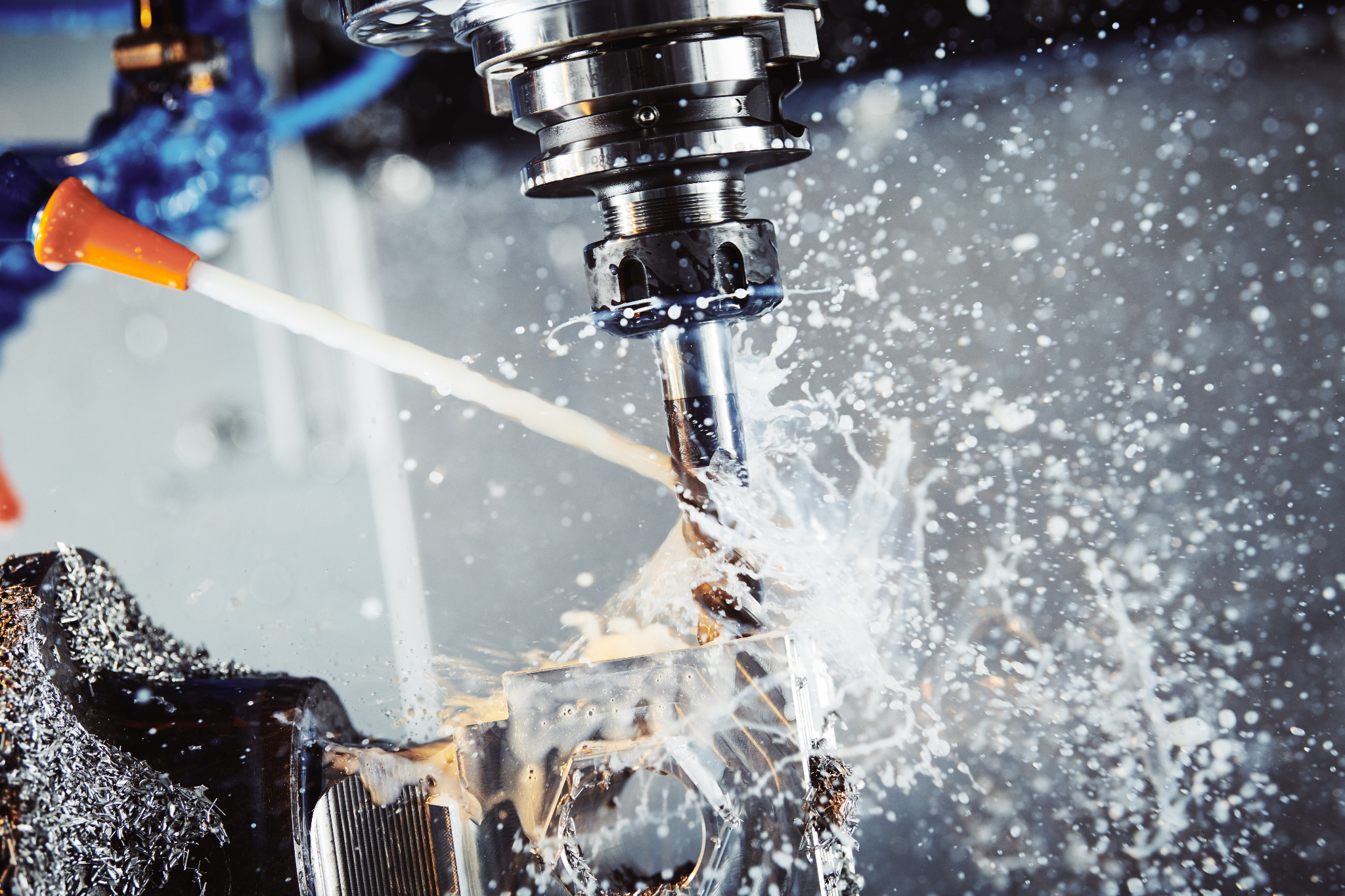
- Coolant: removes heat and can reduce wear.
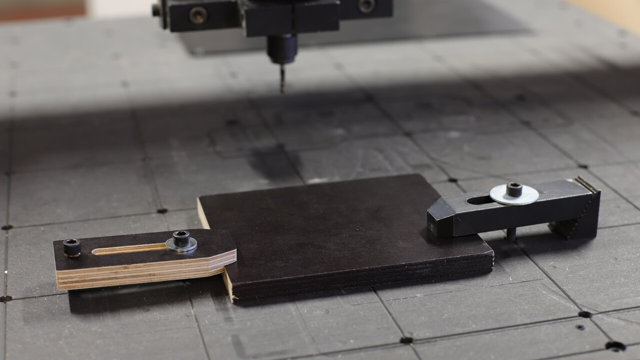
- Clamping: an inadequately fixed workpiece can move during machining.
- Machine rigidity: a rigid machine vibrates less and generally produces a better finish and more accurate dimensions.
4. CAD and CAM
4.1 What Is CAM?
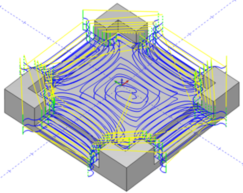
Computer-Aided Manufacturing (CAM) software converts a digital design into operations that production equipment can execute. It generates toolpaths for mills, lathes and other CNC machines; slicers perform the equivalent role for 3D printers.
CAM settings describe the real manufacturing process. A 3D-print slicer needs temperature, speed, layer height, infill and wall settings. CNC CAM needs tool type and diameter, operation order, toolpath strategy, depth, spindle speed and feed. The resulting paths are post-processed into G-code for the target controller.
4.2 Relationship Between CAD and CAM
CAD defines the design; CAM defines how to manufacture it. The CAD model is transferred to CAM, where machining operations and toolpaths are created.
4.3 The Role of CAM Software
When a CAD model is exported as STL and sliced in PrusaSlicer, PrusaSlicer is acting as CAM software. Just as printing requires decisions about orientation, support, layer height and material, CNC output requires decisions about tools, paths, operation order, cutting depth and feed. Complicated parts may also require four- or five-axis machining.
Traditional industrial CAM packages can be expensive because CNC predates today's open-source ecosystem. The growth of open-source and lower-cost CAM tools is making CNC more accessible to small organisations and individual makers.
Translation notice: This English page was generated automatically by AI and has not yet been reviewed by a human. It will be checked and revised page by page when time permits.