Brass Cannon
This chapter models a traditional brass cannon. Course time and available machinery may prevent us from manufacturing it on a lathe and milling machine, but the CAD exercise preserves the machining workflow and prepares you for future CNC work.
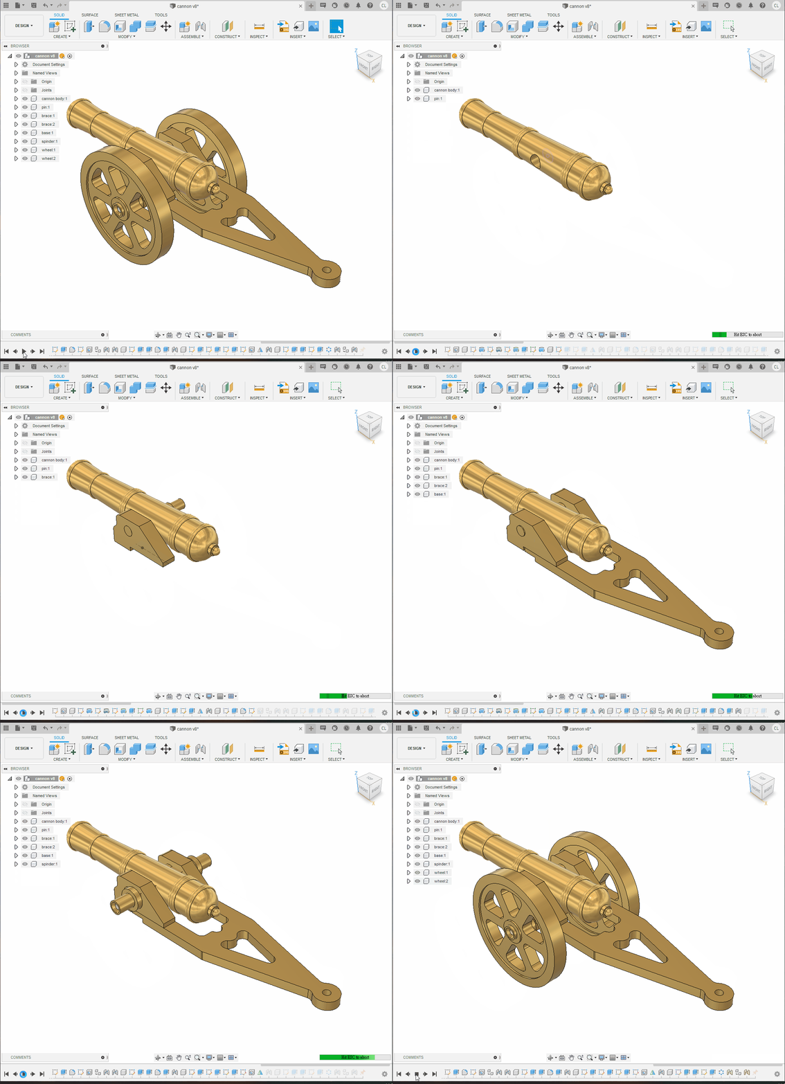
Older video tutorial
Step 1: Cannon Body
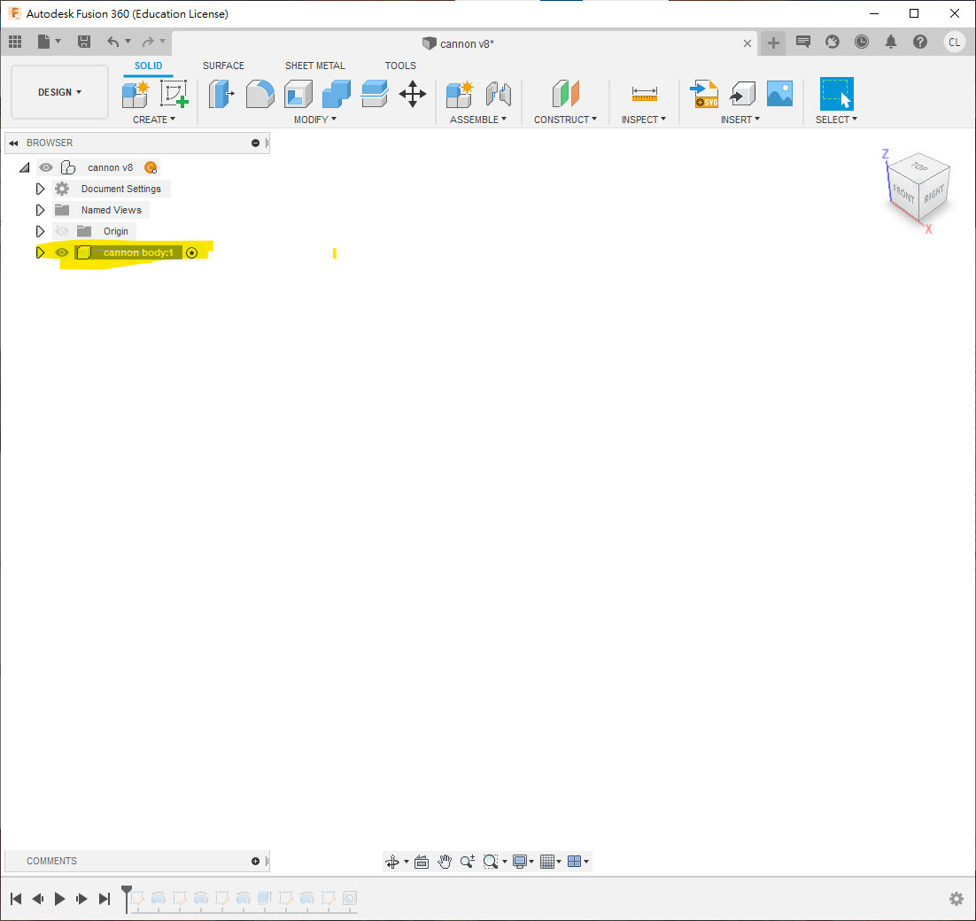
- Create and activate a component named
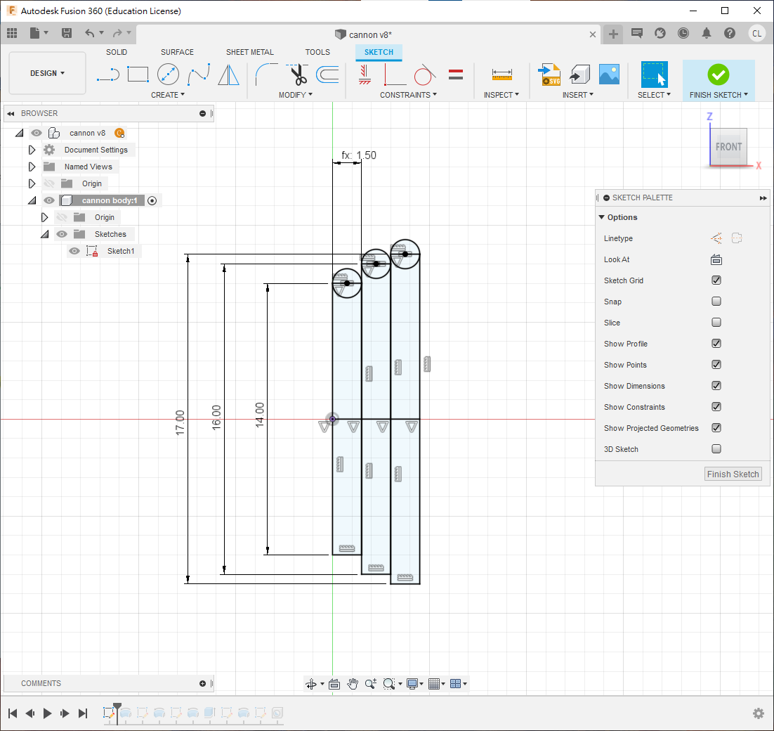
cannon body. - Create a sketch and draw the three rectangles and circle forming the front portion of the profile.
- Open
Change Parametersand createstepSize = 1.5 mmfor later adjustment. - Search for
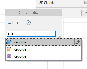
Revolve, select the upper half of the profile and revolve it 360° around the X-axis.
⚠️WARNING
Feature-based applications such as Fusion 360 can become very slow when a single 2D sketch contains too much geometry and too many interdependent constraints. Divide a complicated profile among several sketches.
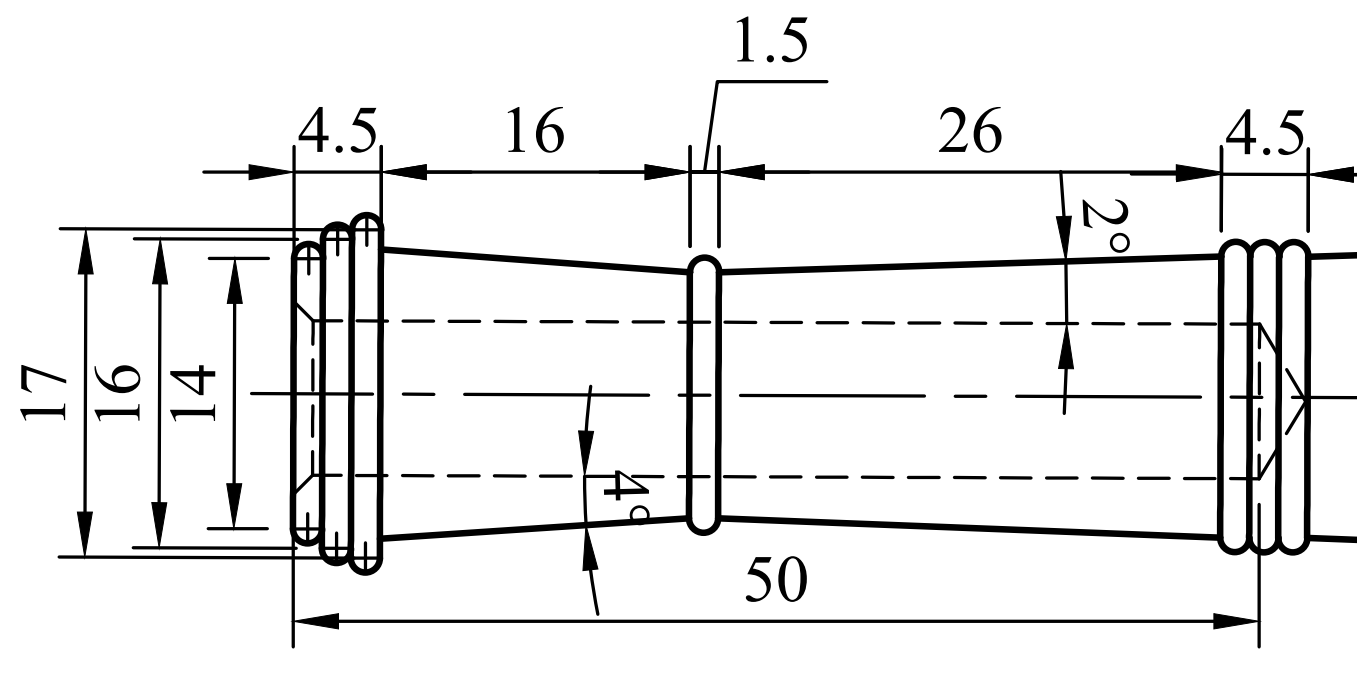
Create another sketch inside cannon body. Press P to project the existing body, continue the profile to the drawing dimensions, then revolve the new region 360° around the X-axis.
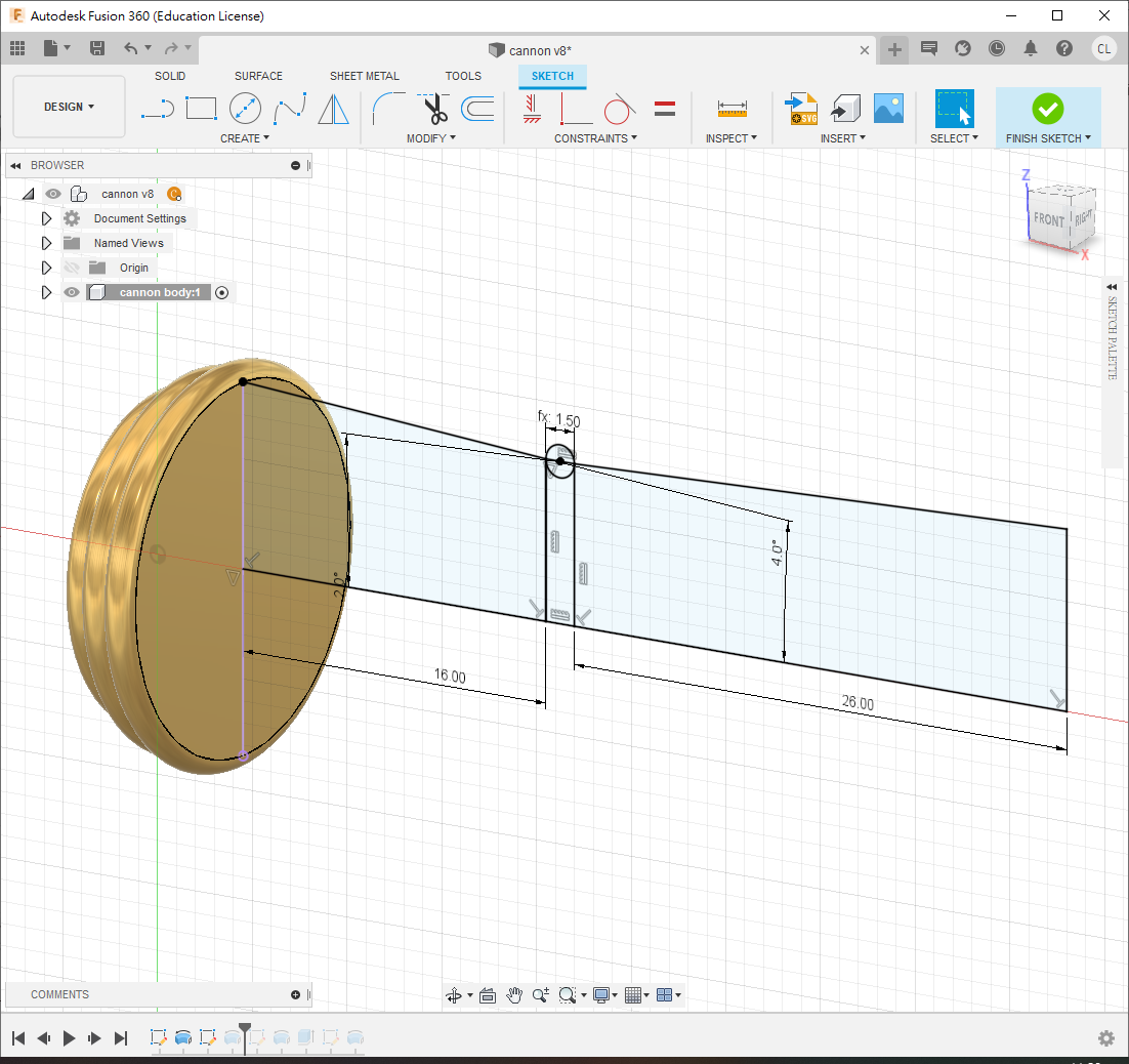
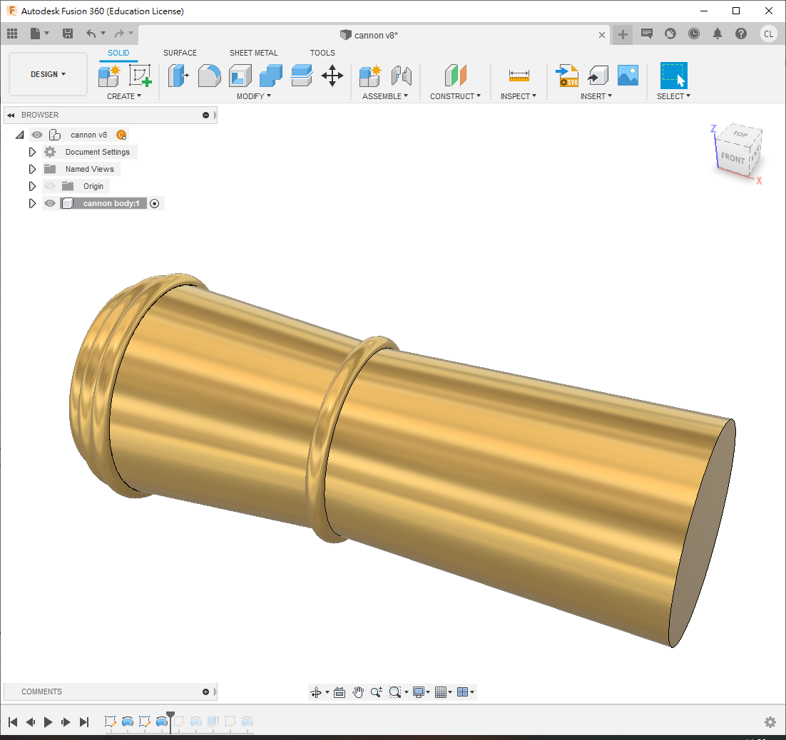
Create cannonBodyHole = 8 mm in Change Parameters and continue modelling the bore and stepped profile.
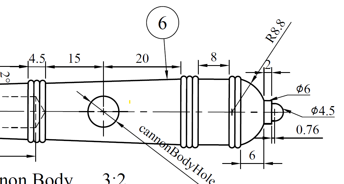
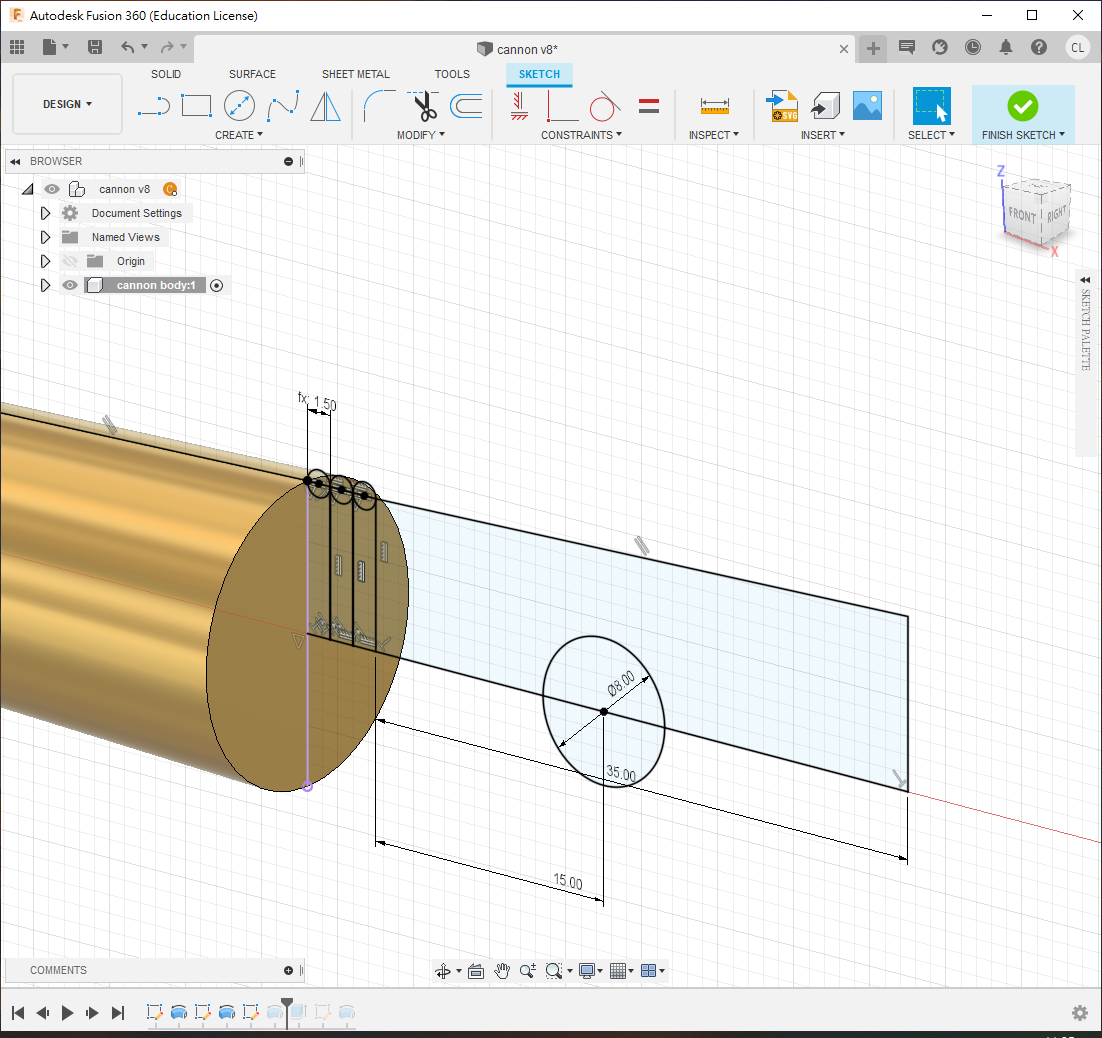
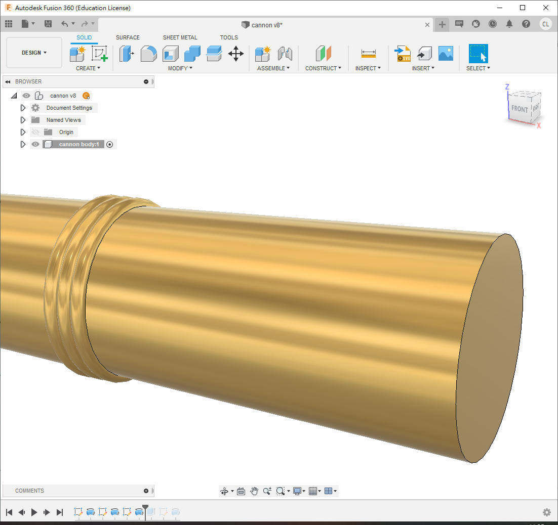
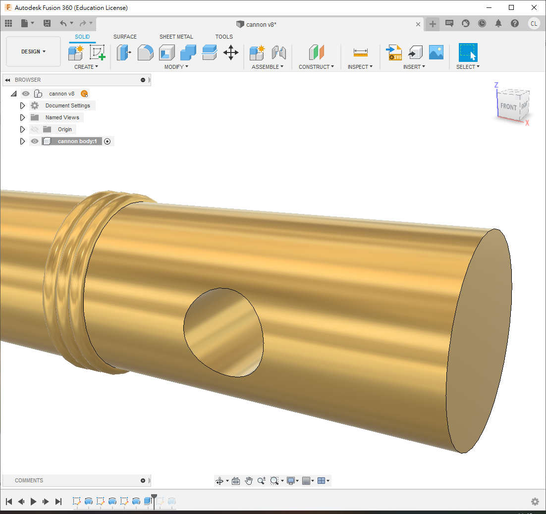
Continue from the PDF dimensions. Draw curved sections with 3-Point Arc, defining their start point, endpoint and radius.
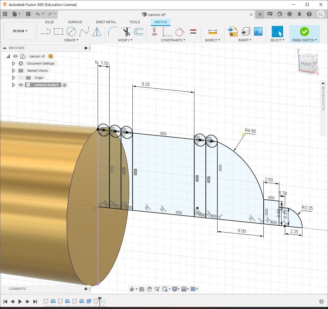
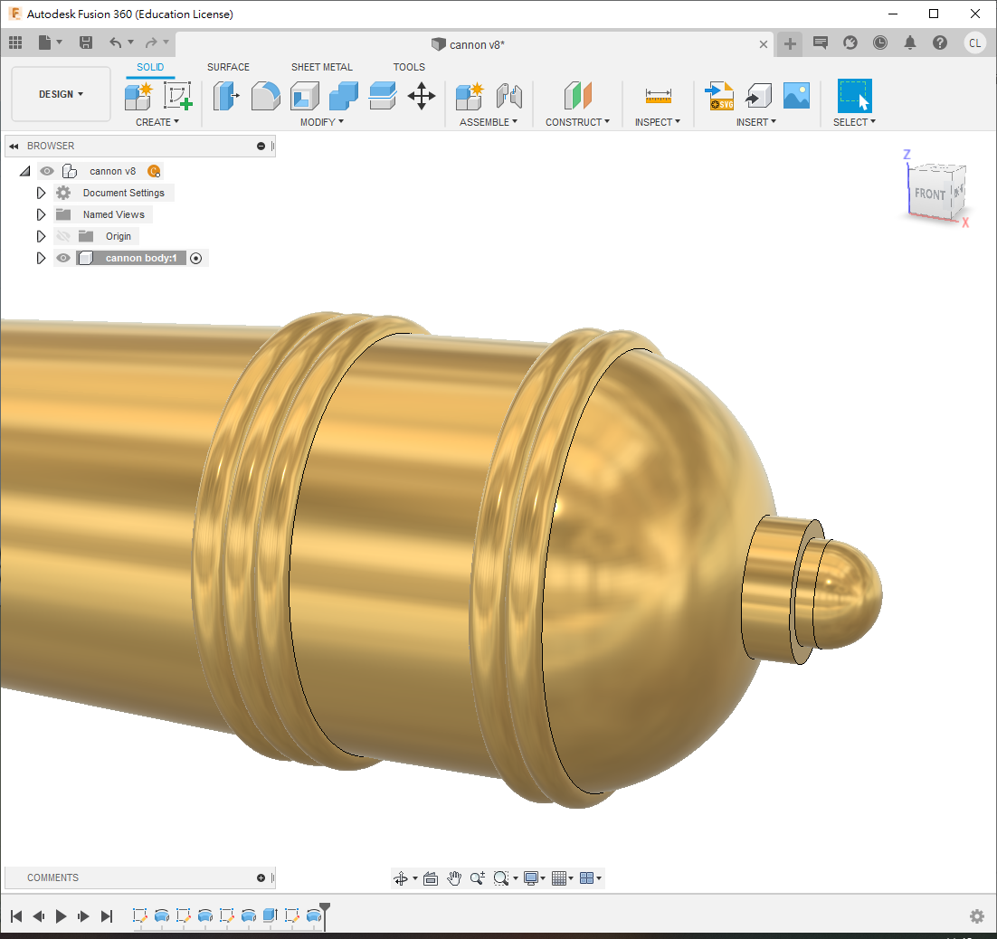
Step 2: Trunnion Pin
- Create and activate a component named
pin. - Show the original sketch under
cannon bodyand hide the cannon body. - Create a sketch and press
Pto project the circle from the original sketch.
💡TIP
Project the original sketch, not the solid edge, because the solid edge does not provide the circle's centre point.
- Create
baseWidth = 21 mm. - Press
E, chooseSymmetric, and extrude tobaseWidth.
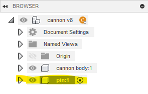
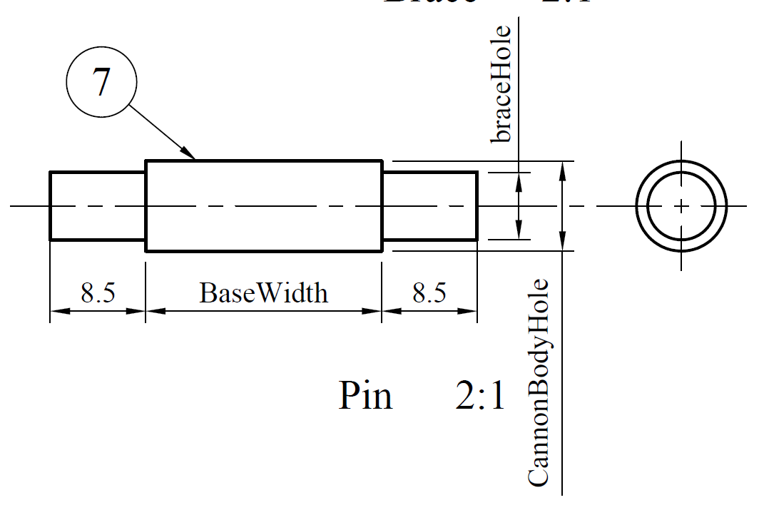
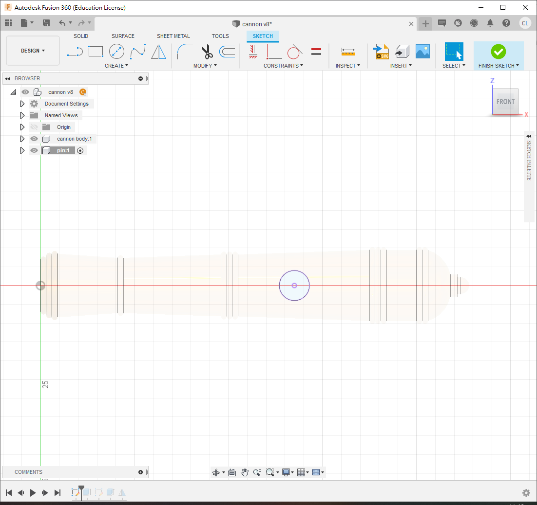
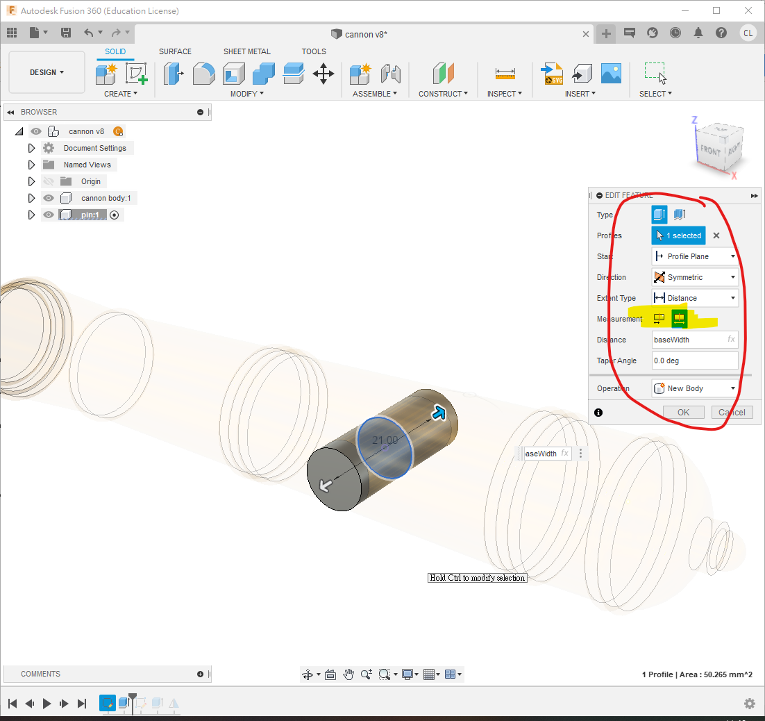
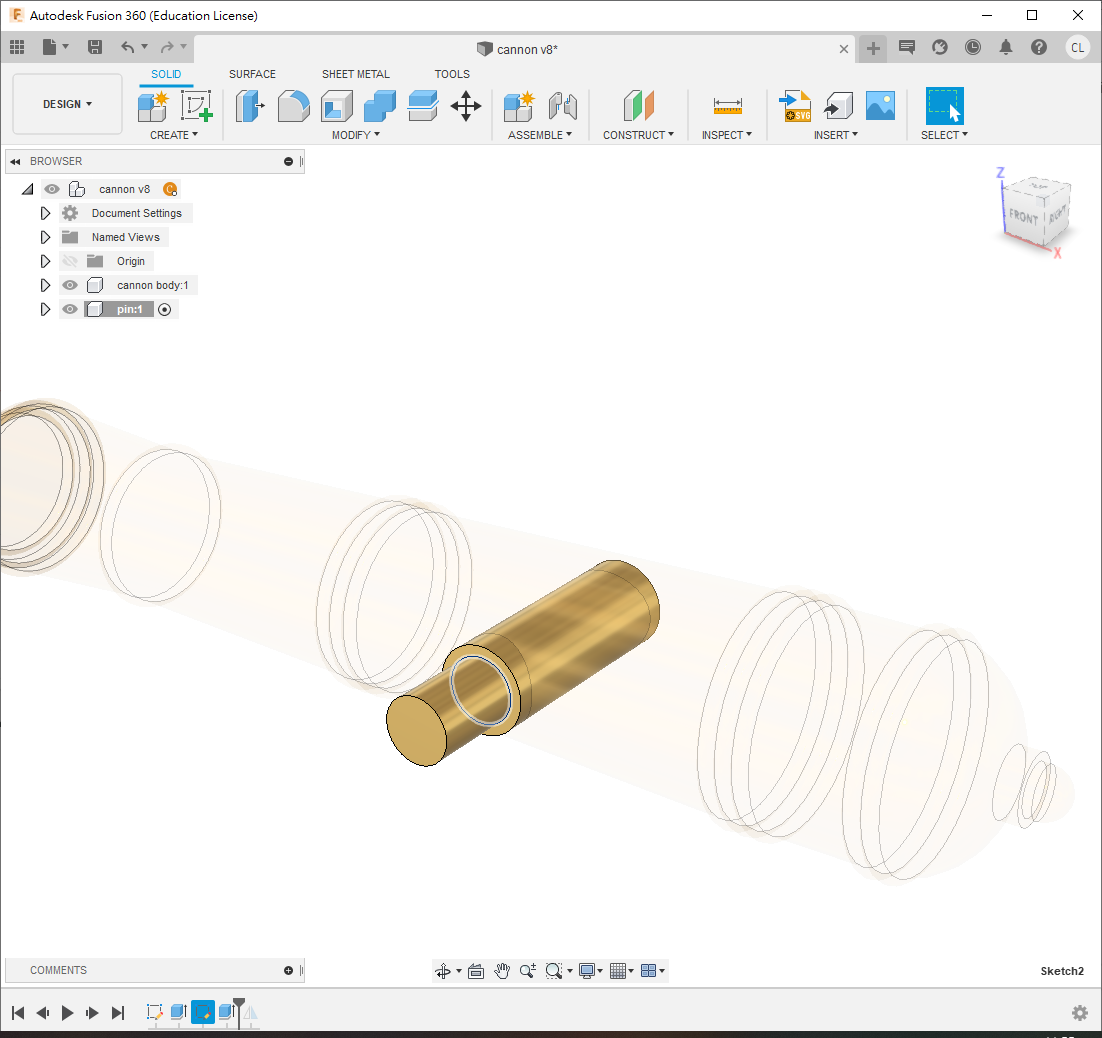
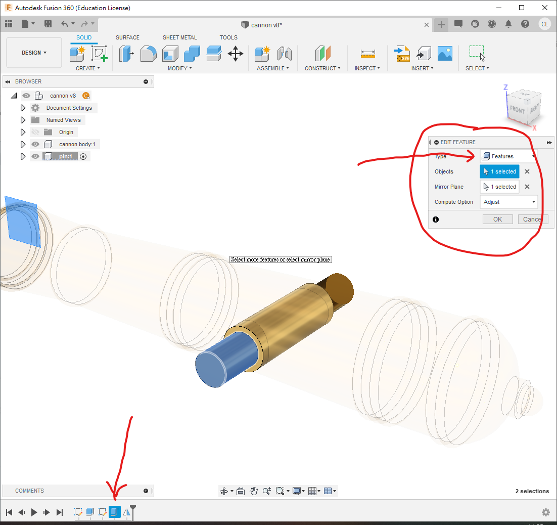
Create braceHole = 6 mm. Sketch a circle on one side and extrude it 8.5 mm. Mirror that extrusion across the world XZ plane. Press J and connect pin to cannon body with a Revolute joint.
Step 3: Braces
Create and activate brace. Sketch on the outer end of the pin, project its circle and draw the complete support to the dimensions in the PDF.
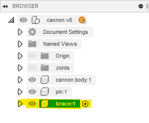
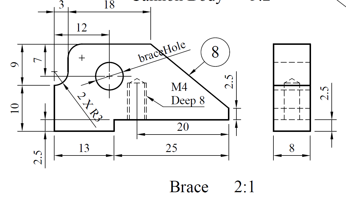
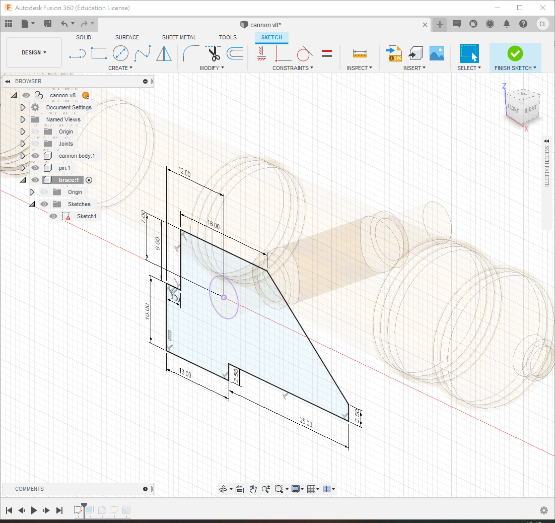
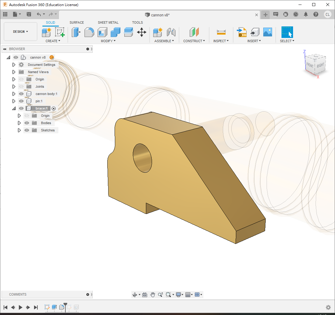
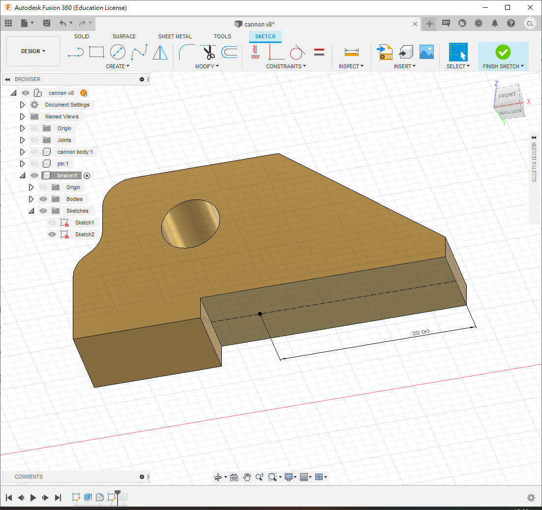
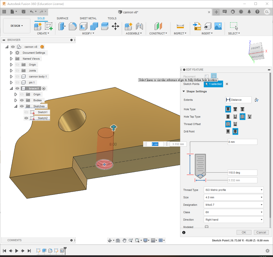
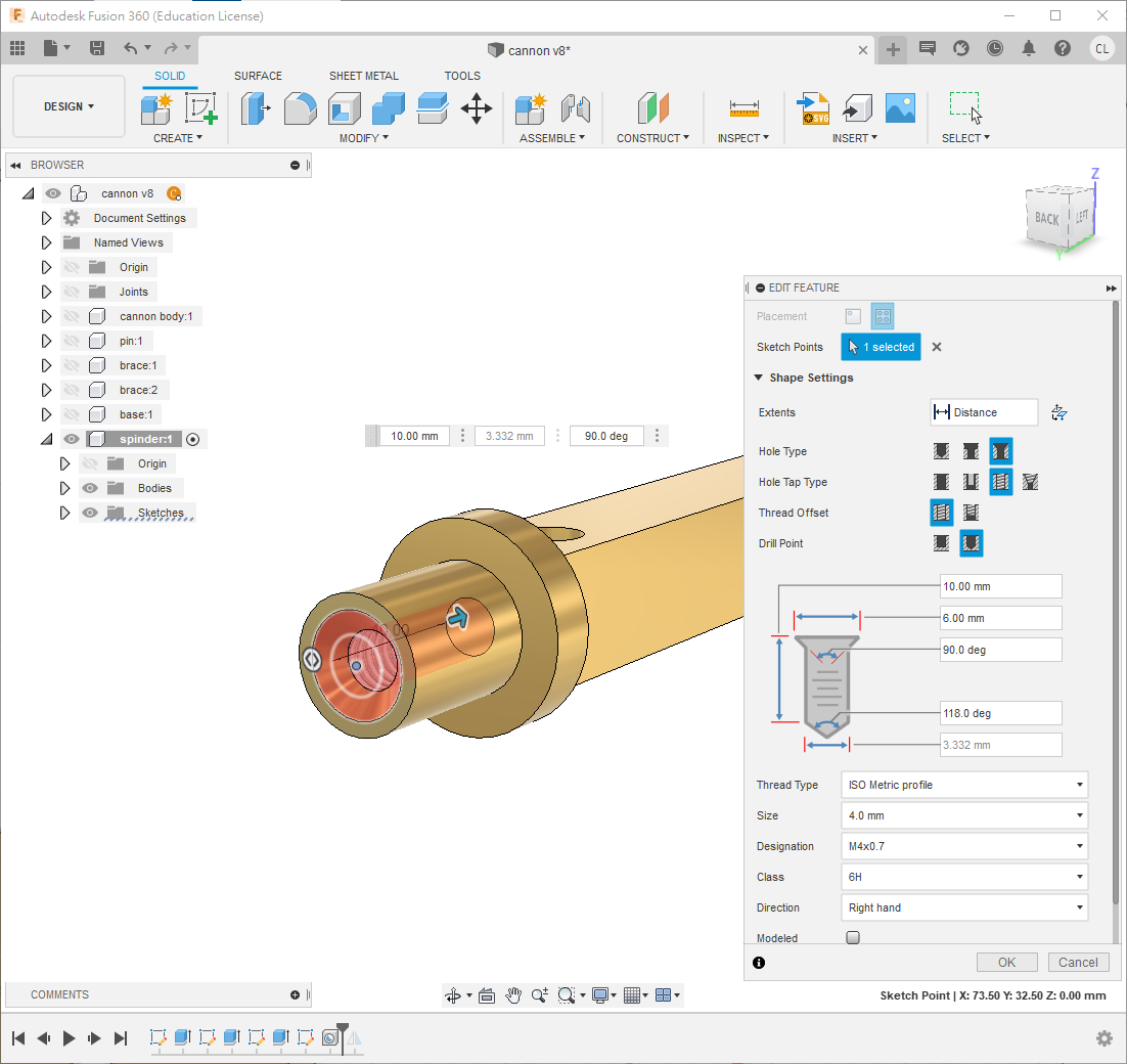
Extrude by 8 mm and apply fillets. On the bottom, sketch a point 20 mm from the edge. Use Hole to create a straight, threaded M4 hole with 8 mm depth, following the remaining settings shown.
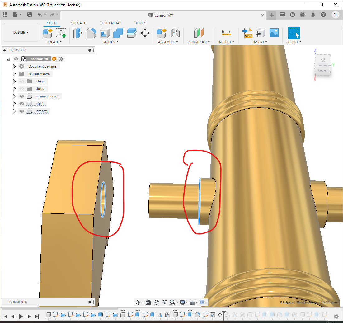
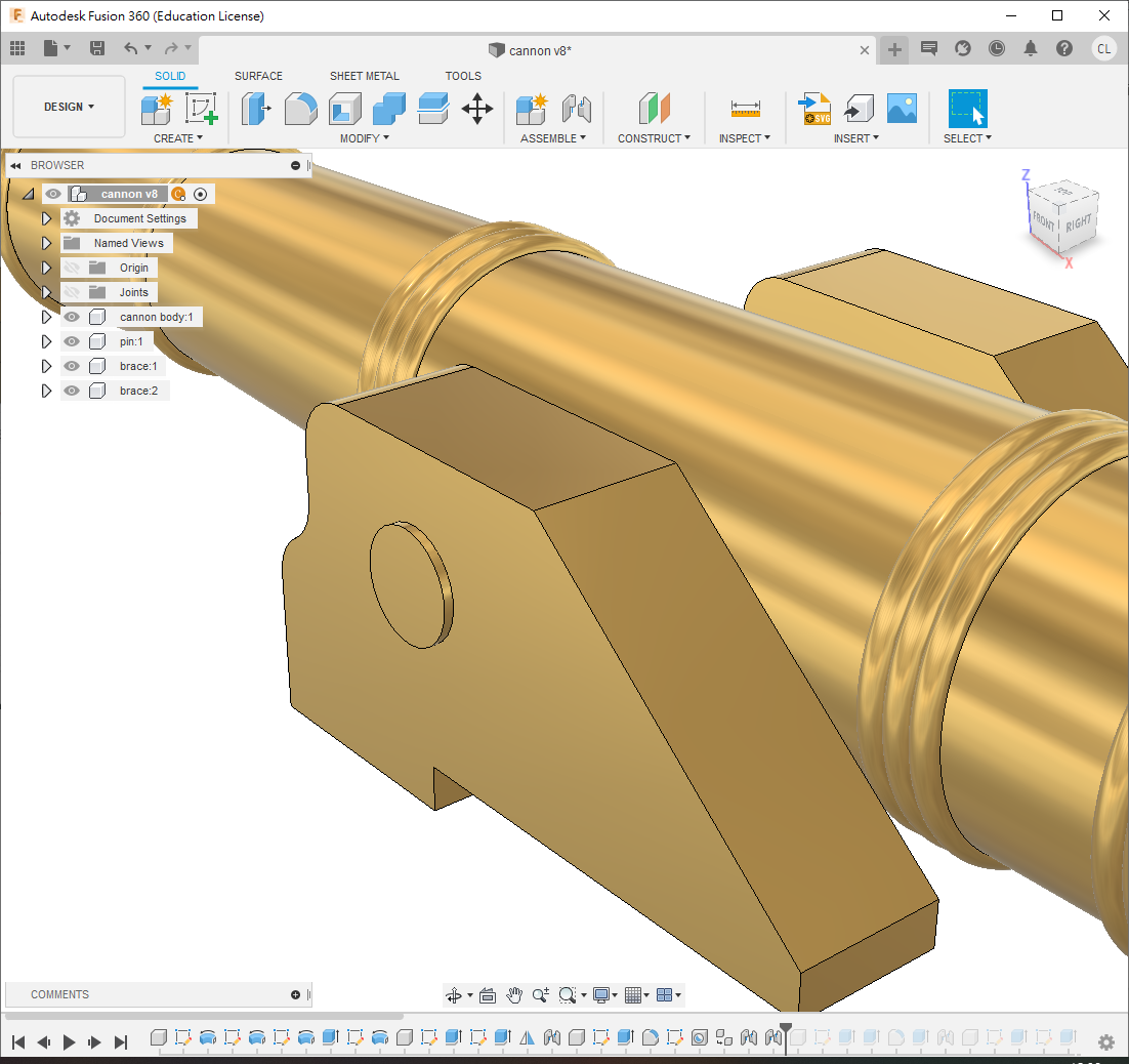
Reactivate the top level, copy and paste the brace, then attach the second brace to the pin with a Revolute joint. The brace is 8 mm thick while the pin projects 8.5 mm, so a 0.5 mm projection is intentional.
Step 4: Base
Reactivate the top level, create and activate base, then sketch on the XY plane or underneath a brace. Follow the PDF. Most rounded corners can be added later; however, the central R4.5 circle does not form a single line with the two lines offset by 8 mm, so construct that transition in the sketch with TTR (tangent–tangent–radius).
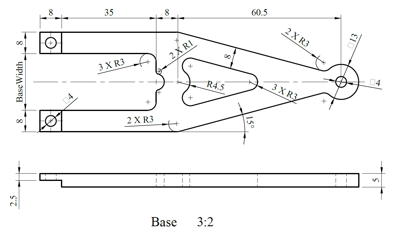
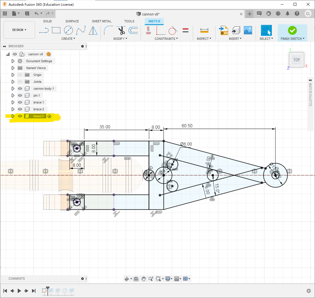
Extrude the regions and add the fillets. Press J and rigid-joint the base to one brace.
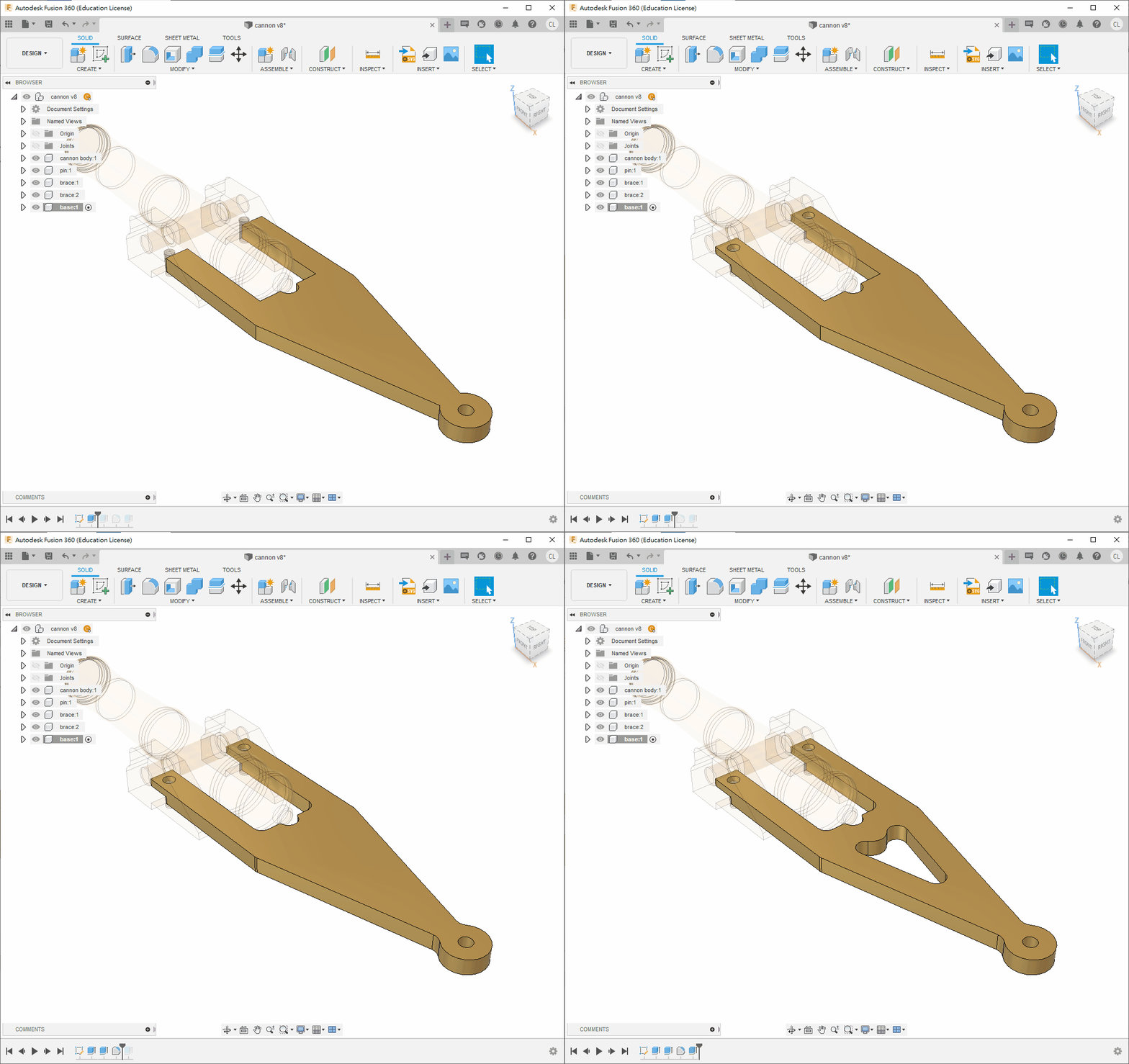
Step 5: Spindle
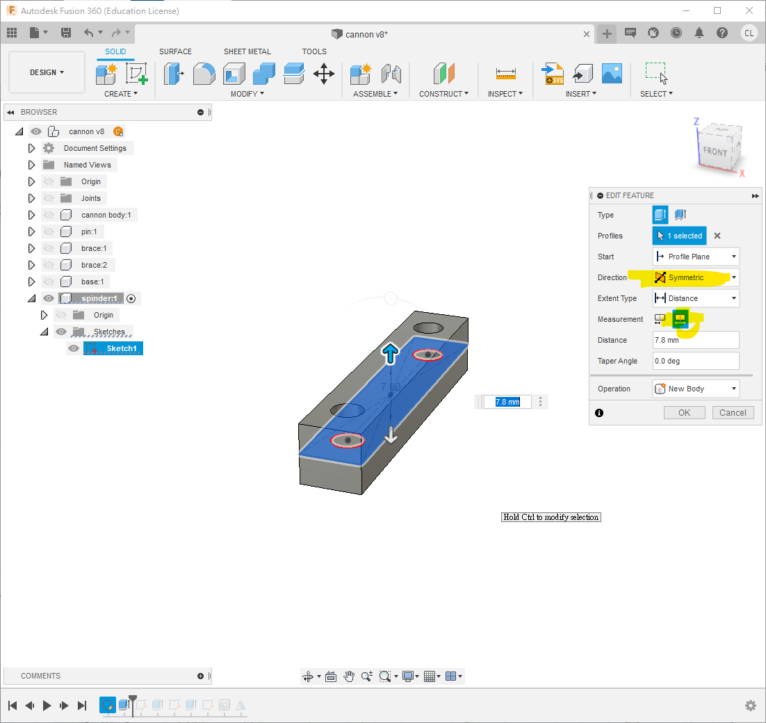
At the top level, create and activate a component named spinder (spindle). Sketch on the XY plane or under base. Press P to project the two 4 mm holes and draw a symmetrical 40 × 7.8 mm rectangle. Extrude it symmetrically by 7.8 mm, then sketch and extrude the 12.5 mm and 7.8 mm circular sections.
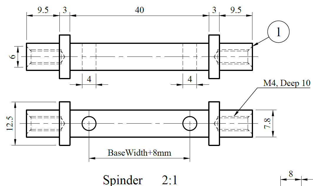
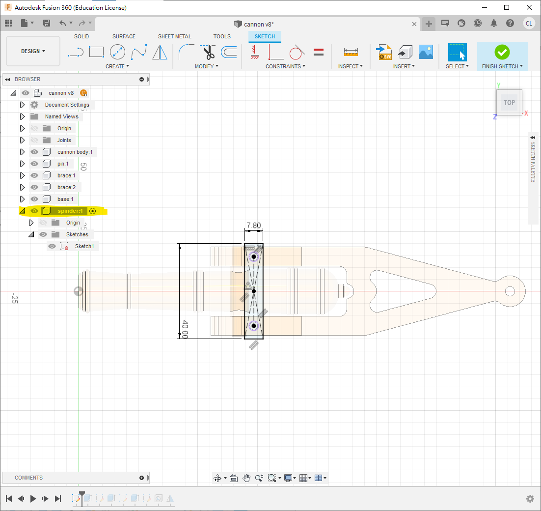
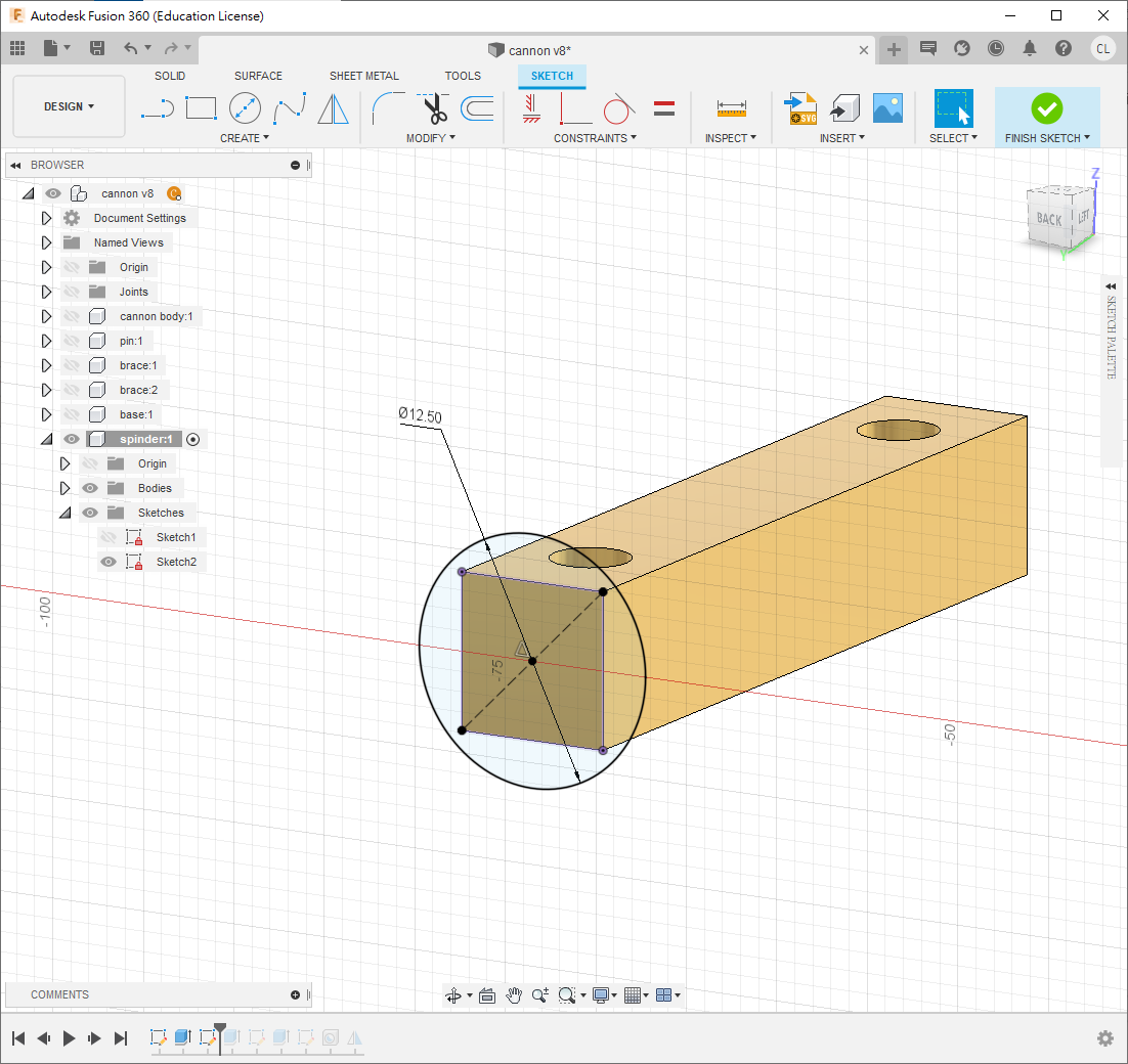
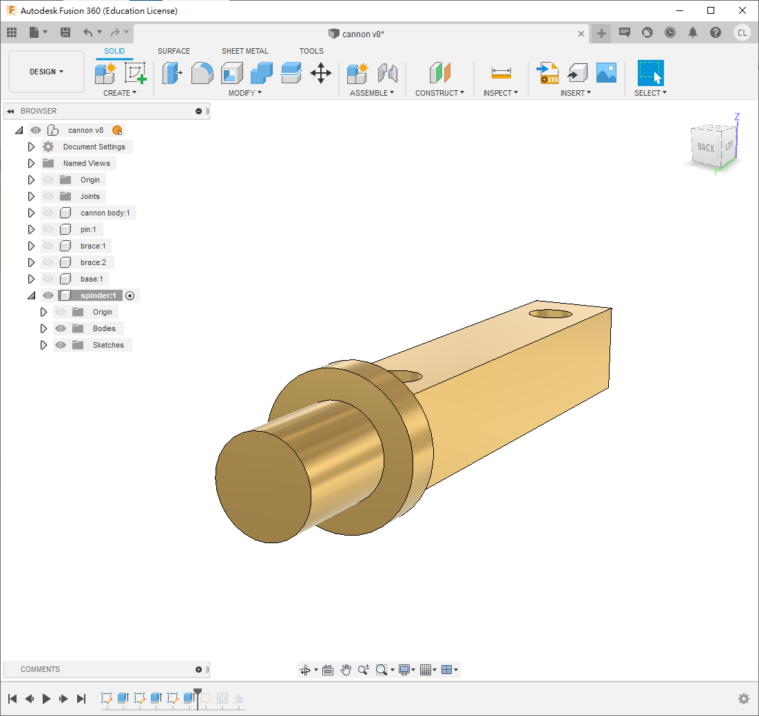
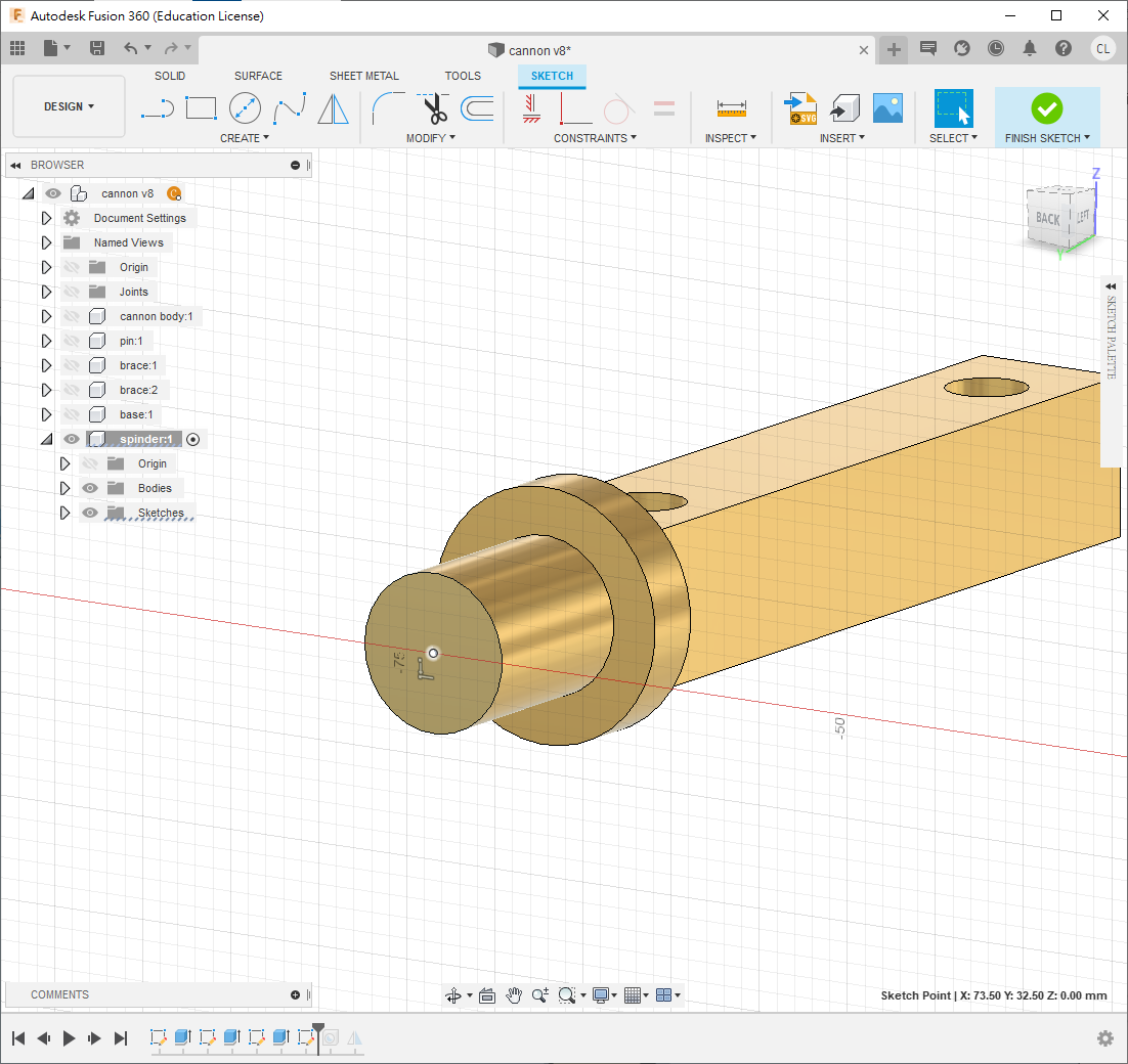
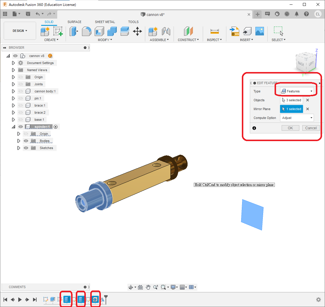
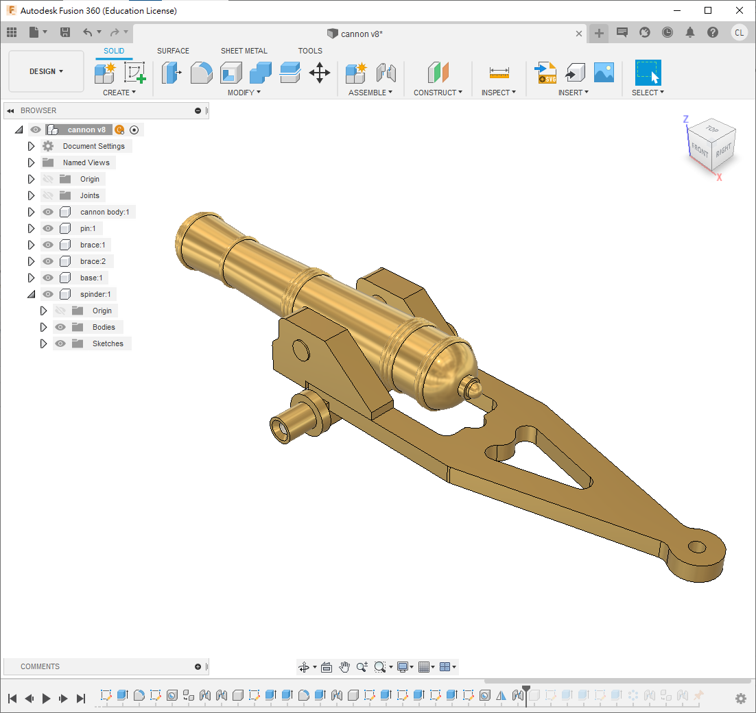
Create a sketch on the outer face and place or project a point. Use Hole to create the counterbored threaded hole shown. Mirror the extrusion and hole features across the world XZ plane, then rigid-joint the spindle to the earlier assembly.
Step 6: Wheels
At the top level, create and activate wheel. Create a sketch and project the centre point of the spindle. Draw four concentric circles of 8 mm, 13 mm, 54 mm and 64 mm diameter. Do not project the spindle circle itself, because it is 7.8 mm rather than 8 mm.
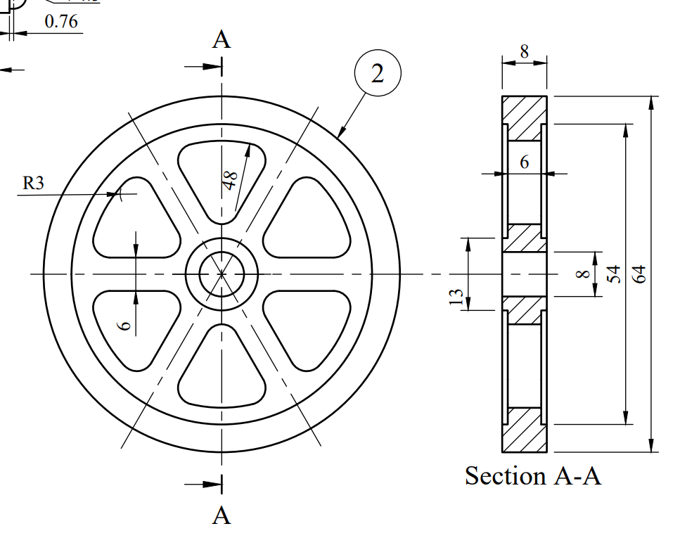
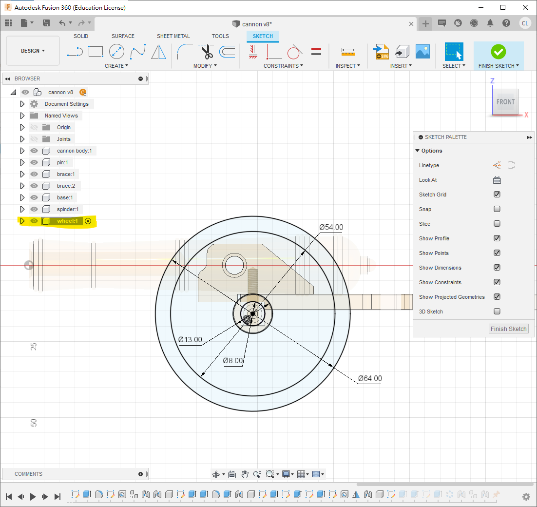
Following the PDF, extrude the wheel sections symmetrically by 8 mm and 6 mm.
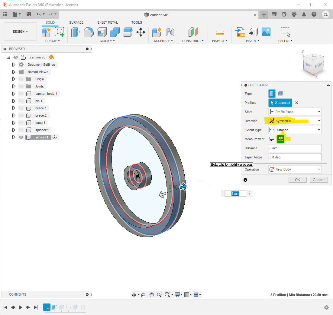
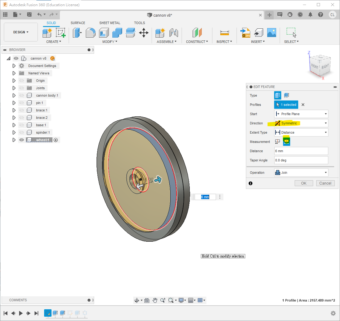
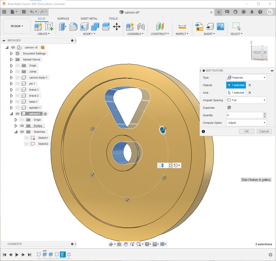
Sketch and cut one opening, then use Circular Pattern to repeat it around the wheel.
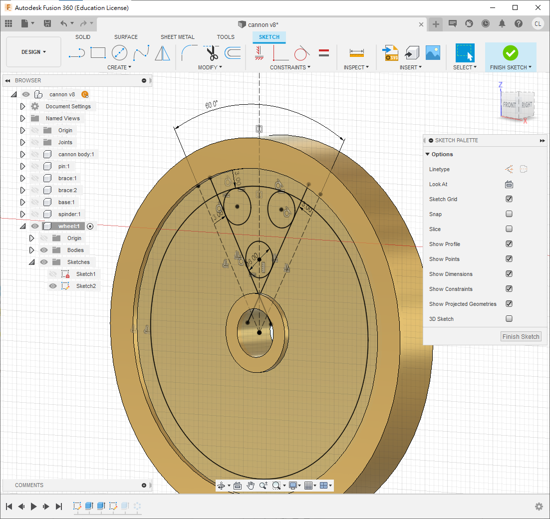
Copy and paste the wheel, then attach both wheels with Revolute joints.
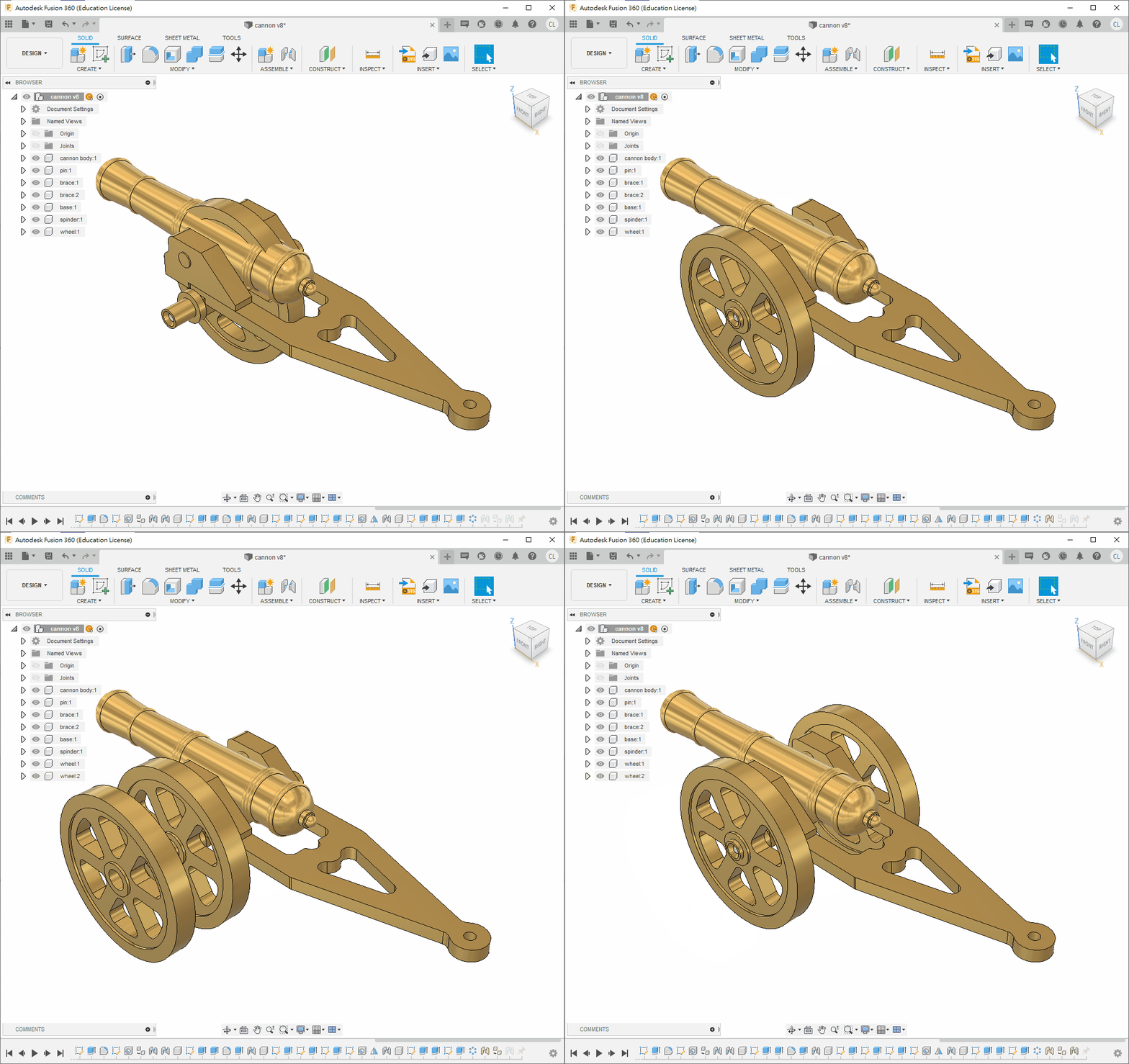
Complete!
Translation notice: This English page was generated automatically by AI and has not yet been reviewed by a human. It will be checked and revised page by page when time permits.