Basic Drawing
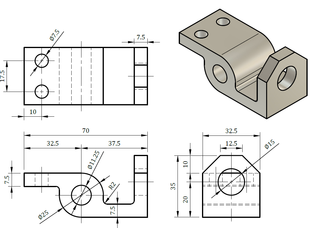
This chapter introduces basic 3D parts built mainly from 2D sketches. You will practise combining sketches on different faces to form a complete model, followed by several exercises.
1. Bracket
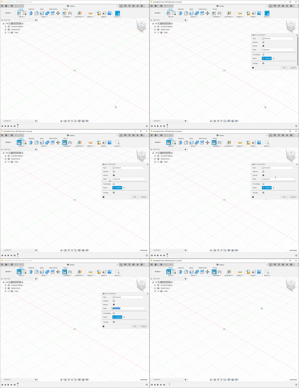
Step 1
- Press
Sto open the command search. - Search for
New Componentand create a component.
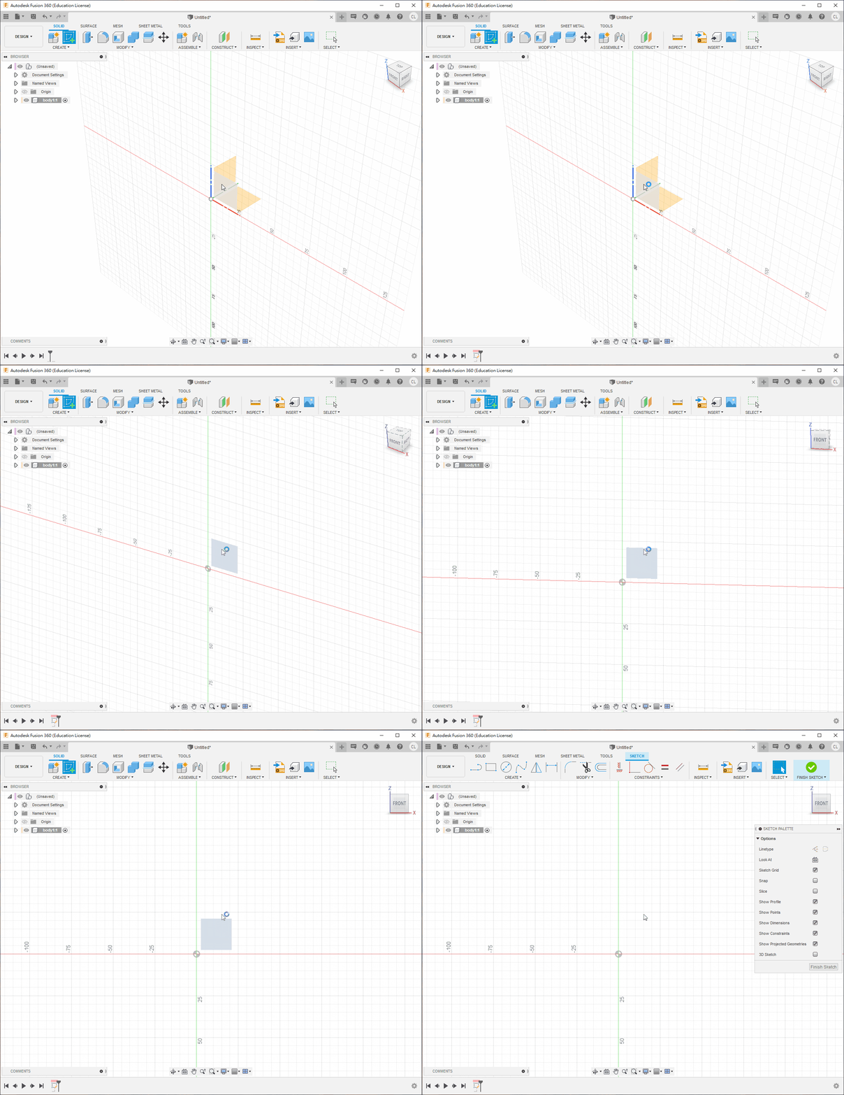
Step 2
- Use
New Sketchto create a 2D sketch on the XZ plane.
- Press
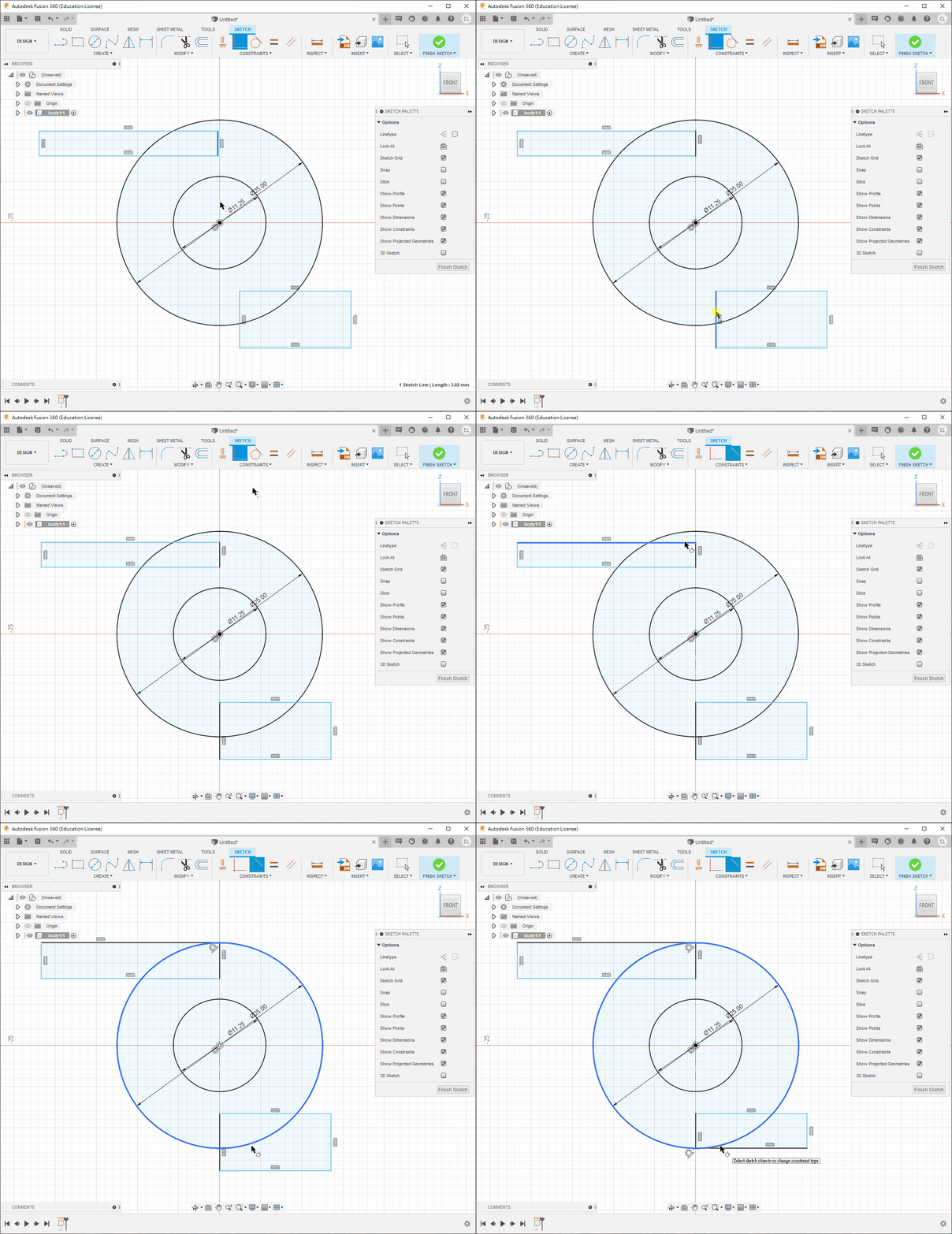
CandRto create circles and rectangles.
💡TIP
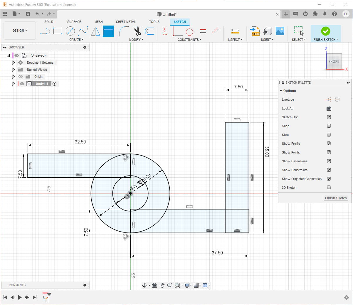
Press D to add dimensions.
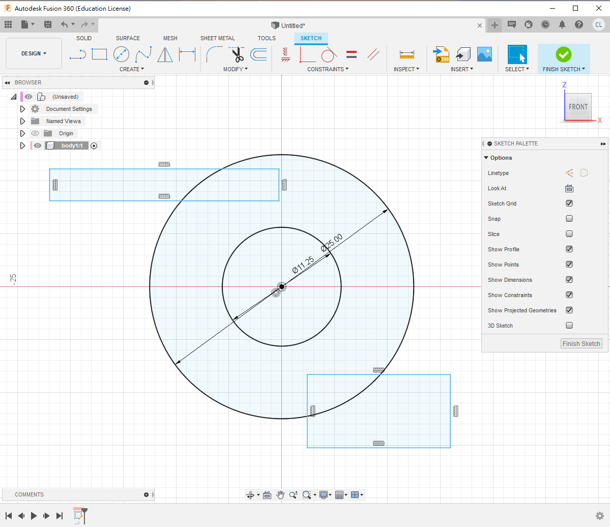
- Apply 2D constraints to make the rectangle tangent and fully constrained, then draw the remaining geometry to the specified dimensions.
- Press
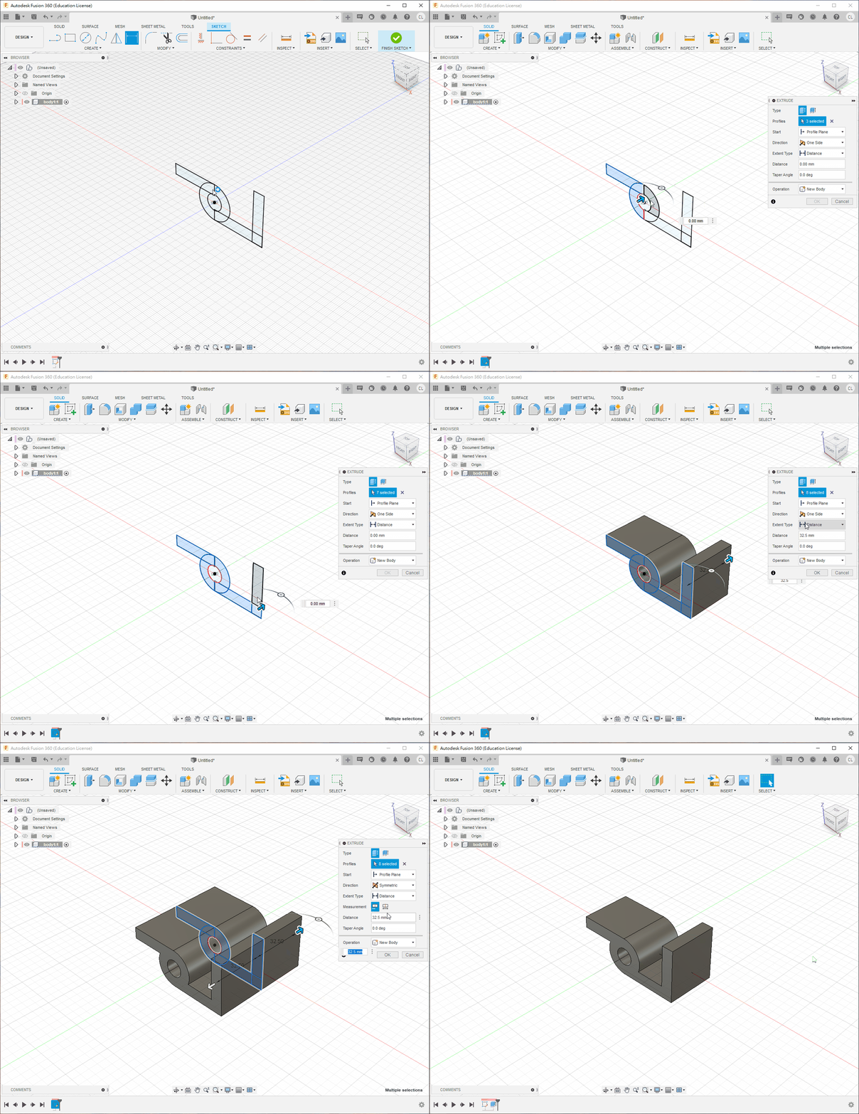
Eand extrude the profile by32.5 mm. A symmetric extrusion is recommended because it simplifies work on the opposite face, although it is not essential.
Step 3
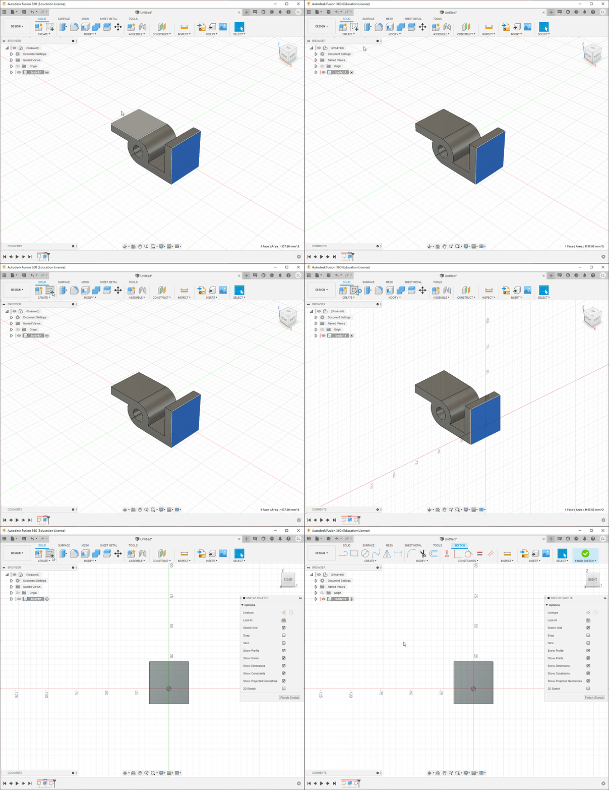
- Create a sketch on the right-hand face.
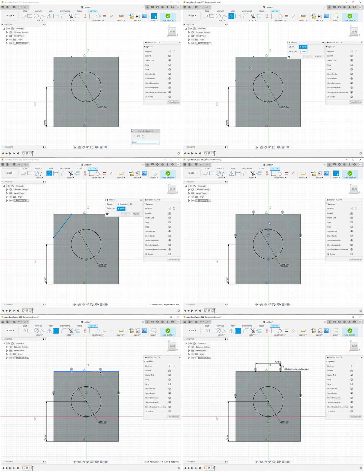
- Draw a centreline and a circle to the specified dimensions.
- Press
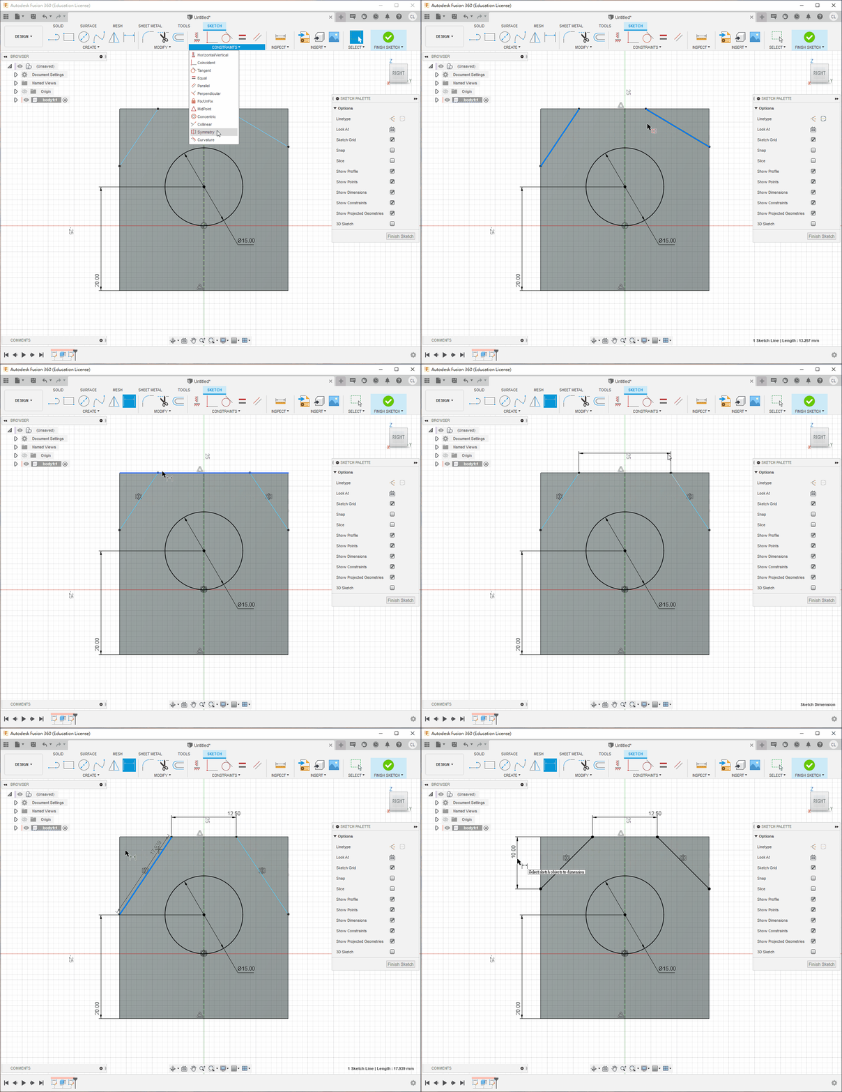
Xto turn the centreline into construction geometry. - Create the sloping sides in either of two ways:
- Draw one side and use
Mirror; or - Draw both sides approximately, then apply the Symmetry constraint.
- Draw one side and use
- Press
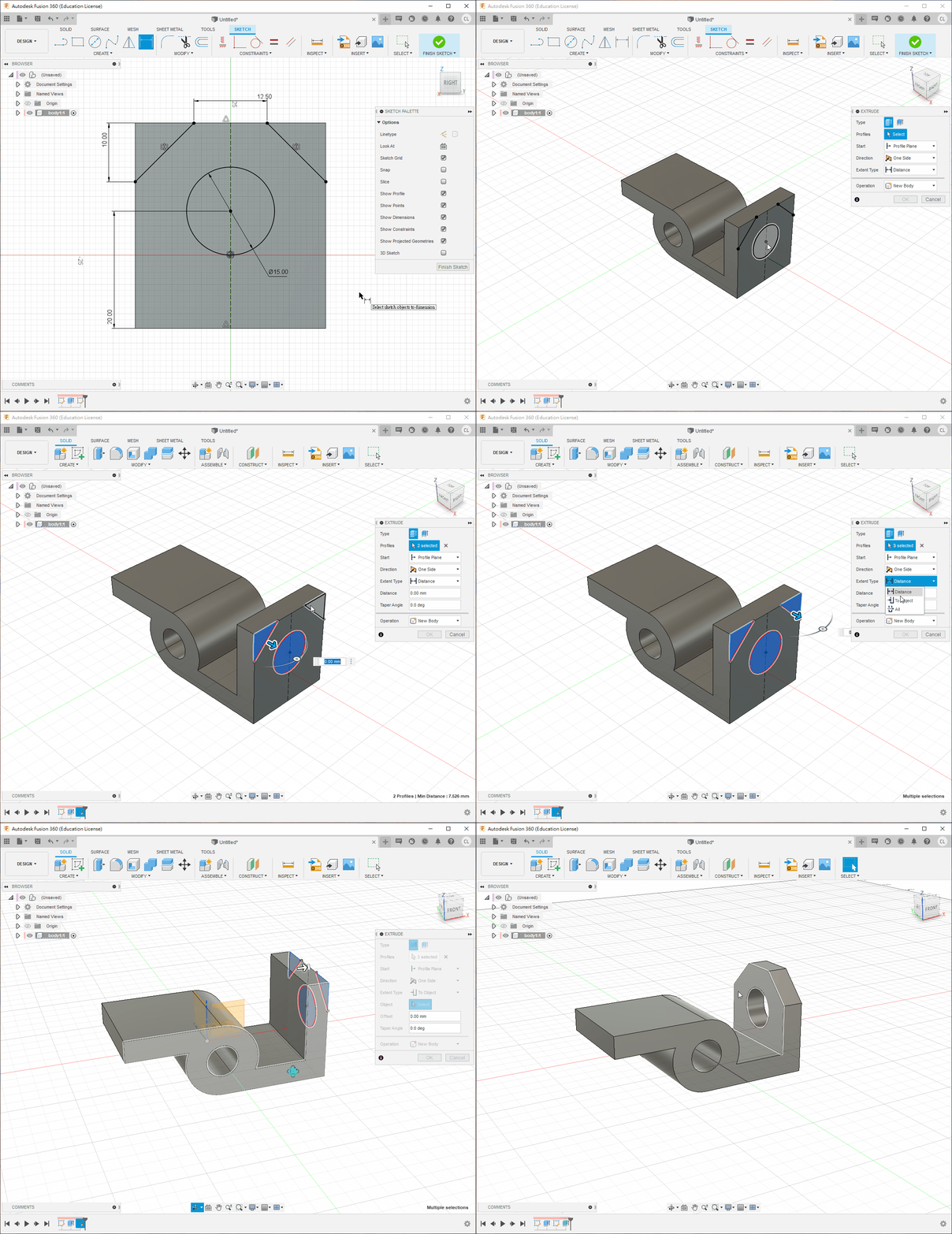
E, select the regions to remove and useTo Objectwith the rear face as the extent.
Step 4
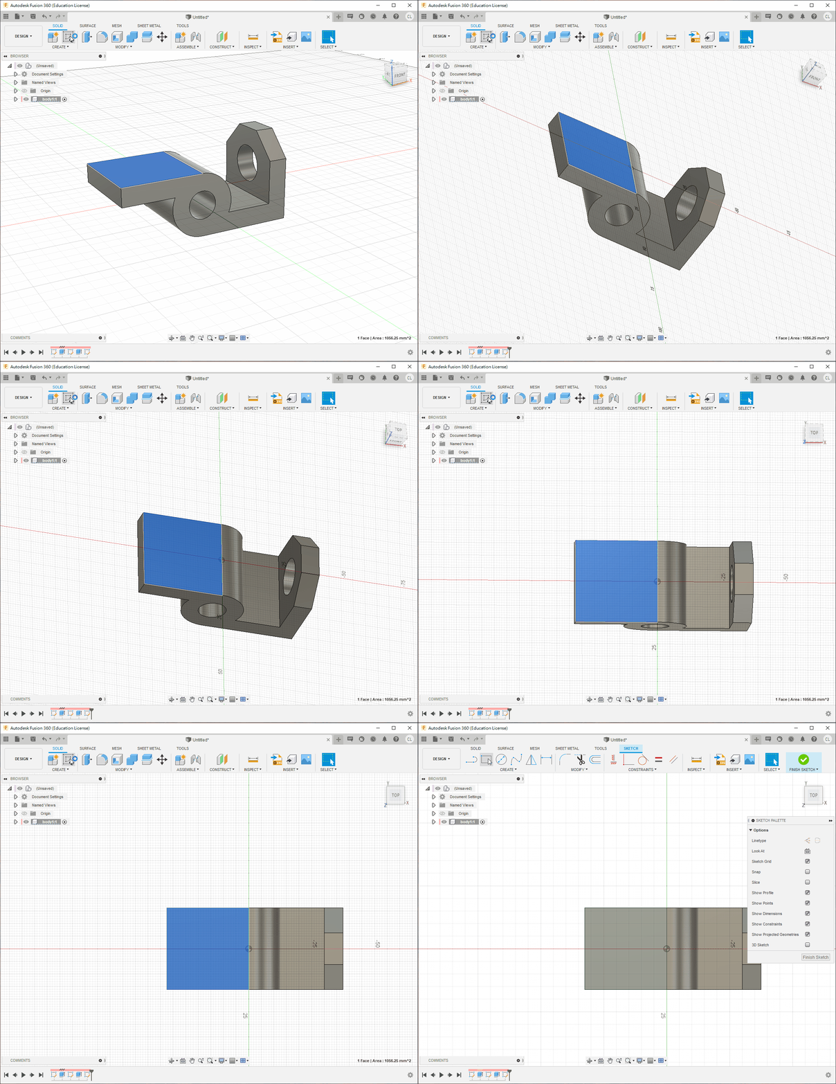
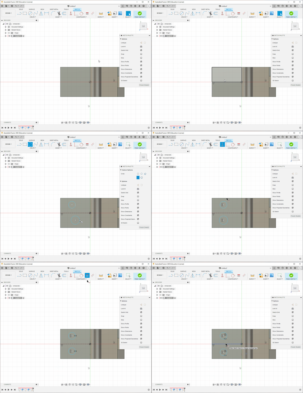
- Create a sketch on the top face.
- Draw a centreline and press
Xto make it construction geometry. - Draw two circles approximately.
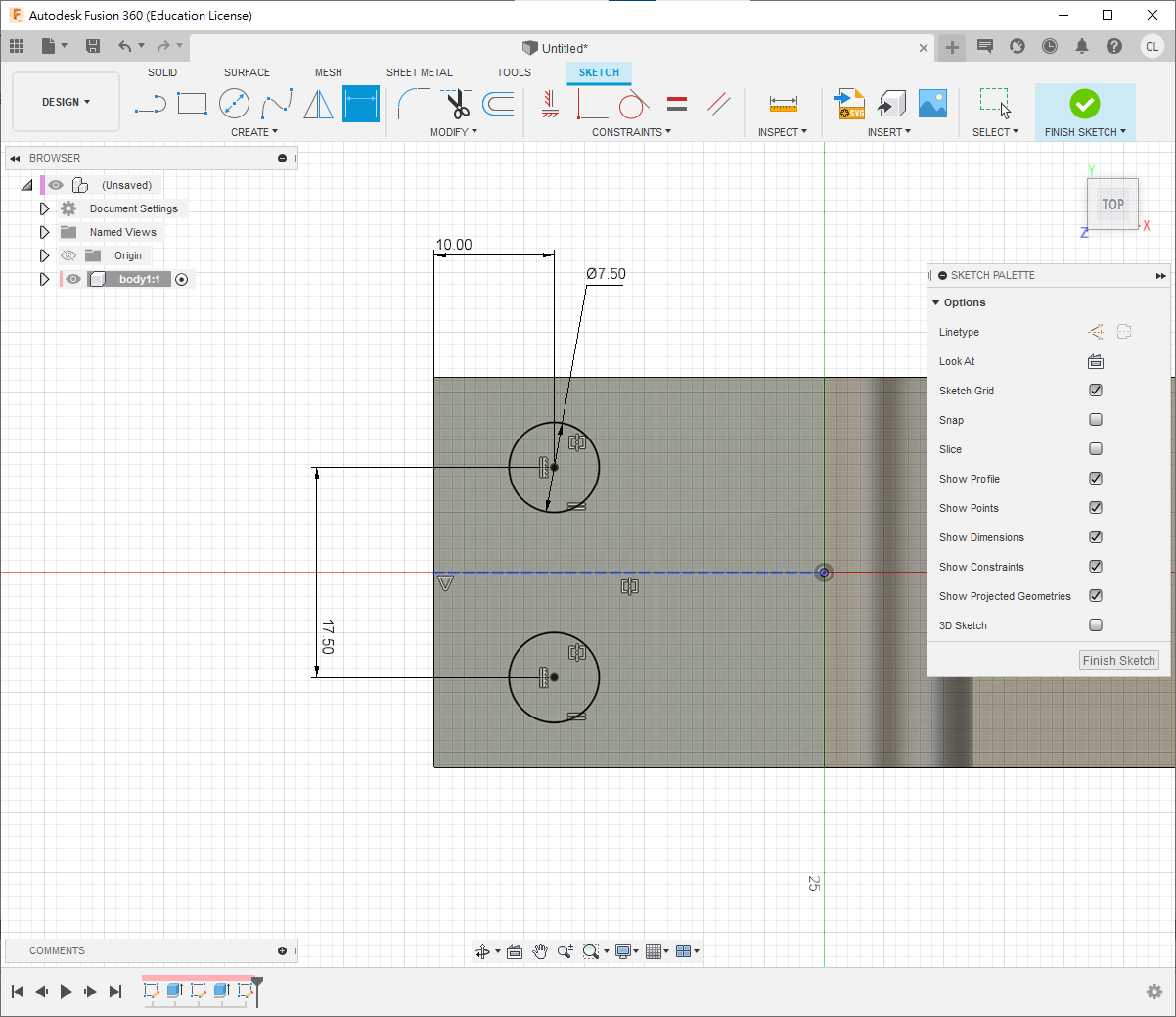
- Apply Equal, Horizontal/Vertical and Symmetry constraints to the circles.
💡TIP
Alternatively, draw one circle and use Mirror.
- Add the remaining dimensions.
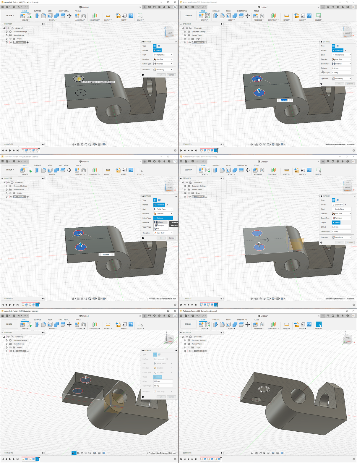
- Press
Eand cut both holes usingTo Object, as before.
Step 5
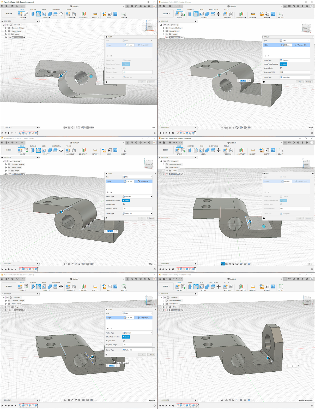
Press F for Fillet, select the three edges and apply a 2 mm radius.
2. Guide Block
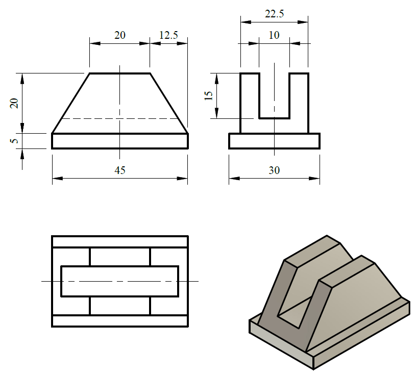
Step 1
- Press
S, search forNew Componentand create a component.
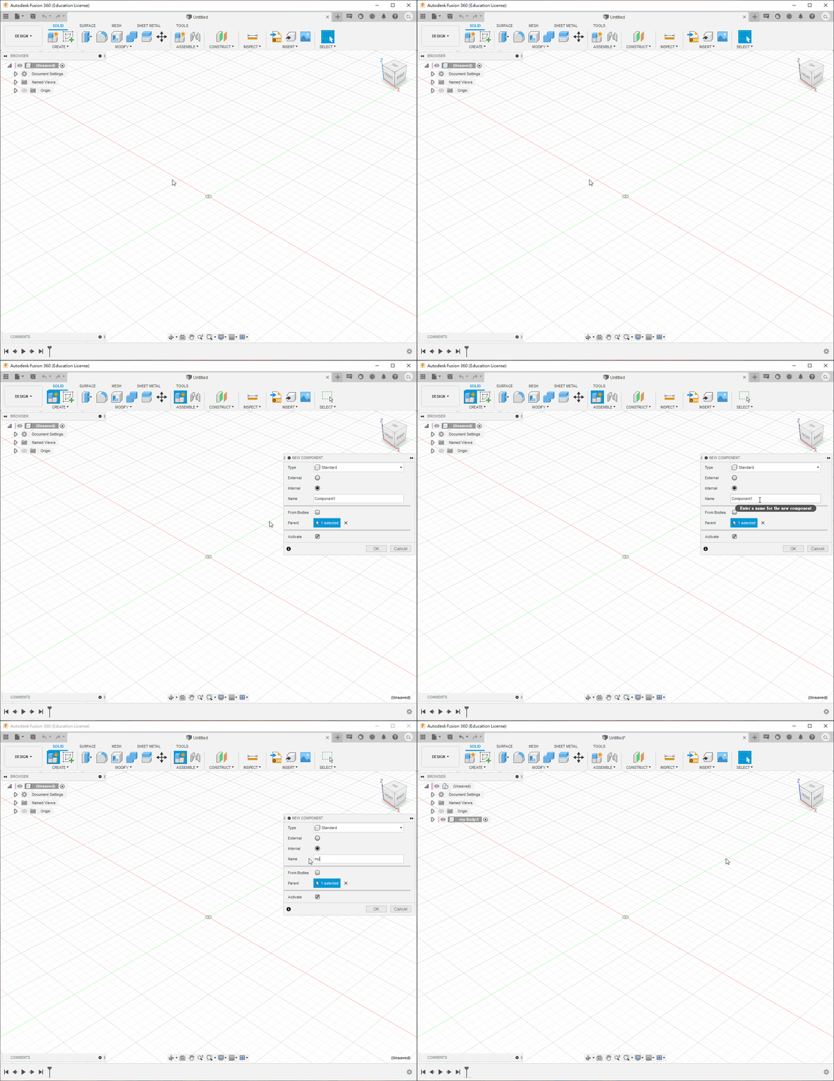
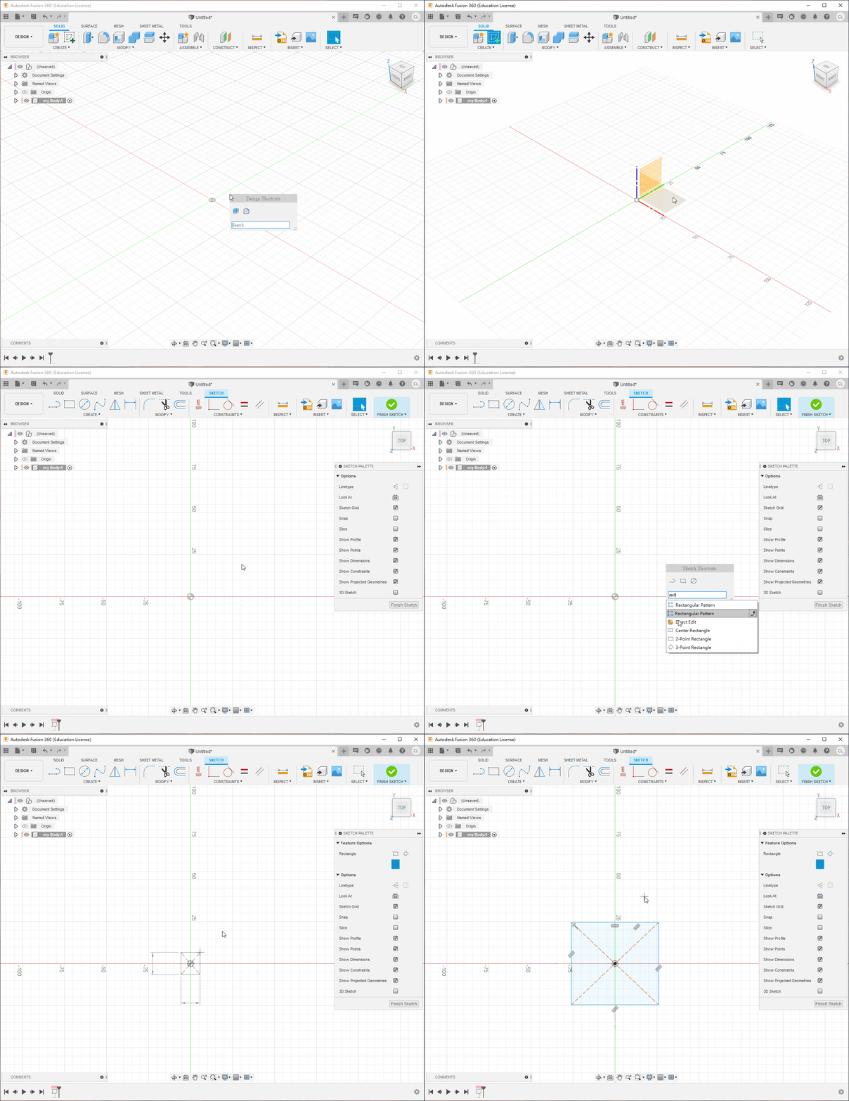
- Search for
Sketchand create a sketch on the XY plane. - Search for
Center Rectangleand draw a rectangle of any initial size from the origin.
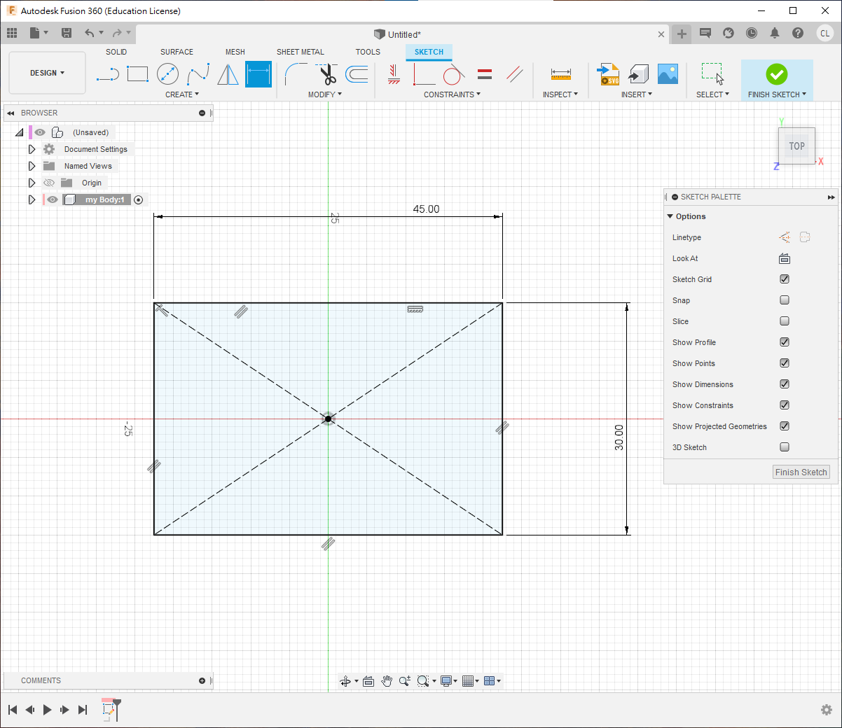
- Press
Dand dimension the rectangle.
- Press
Eand extrude the rectangle to5 mm.
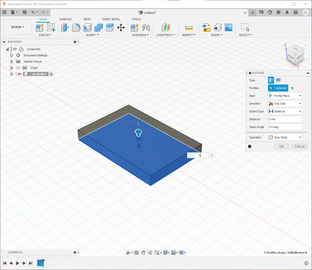
Step 2
- Create a new sketch on top of the base.
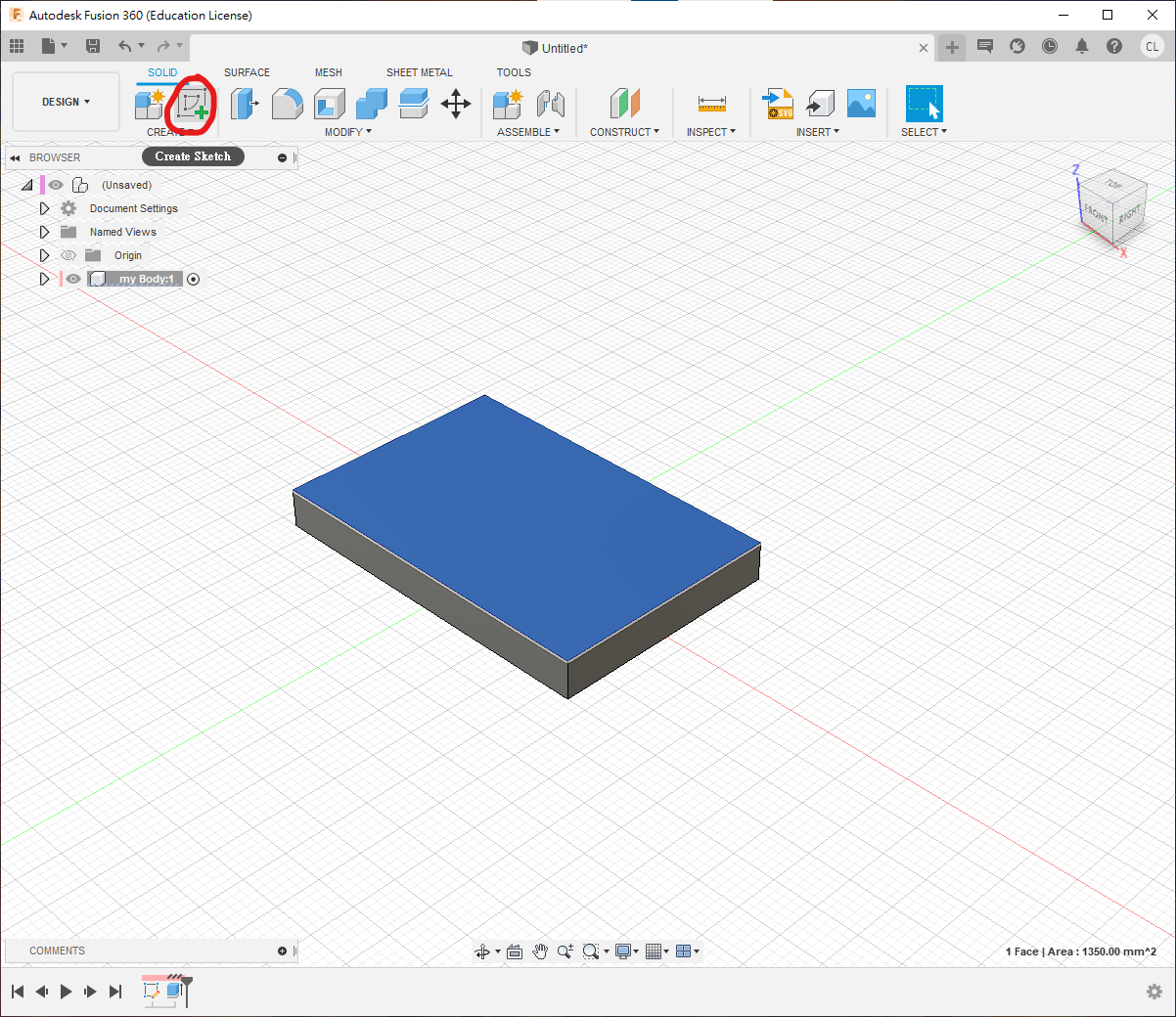
- Draw a slightly smaller centre rectangle.
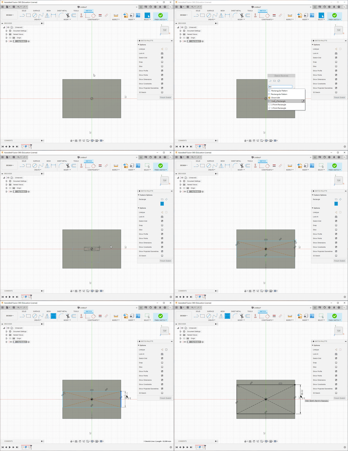
- Extrude it by
20 mm.
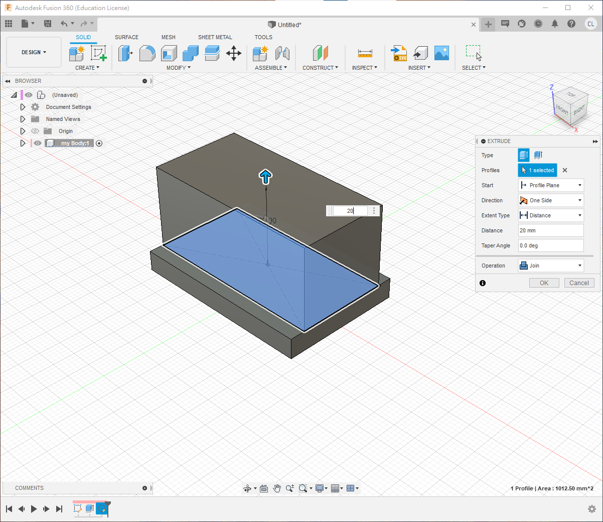
Step 3
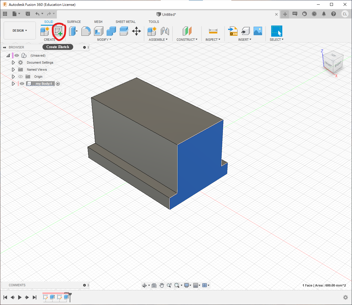
- Create a new sketch on the right-hand face.
- Press
Rand draw a rectangle approximately. - Use the Midpoint constraint to centre it on the edge.
- Press
Dand add its dimensions.

- Press
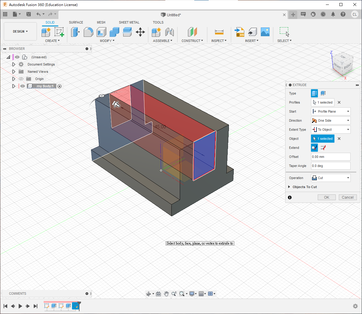
Eand cut the central opening, usingTo Objectwith the left-hand face.
Step 4
- Create a new sketch on the front face.
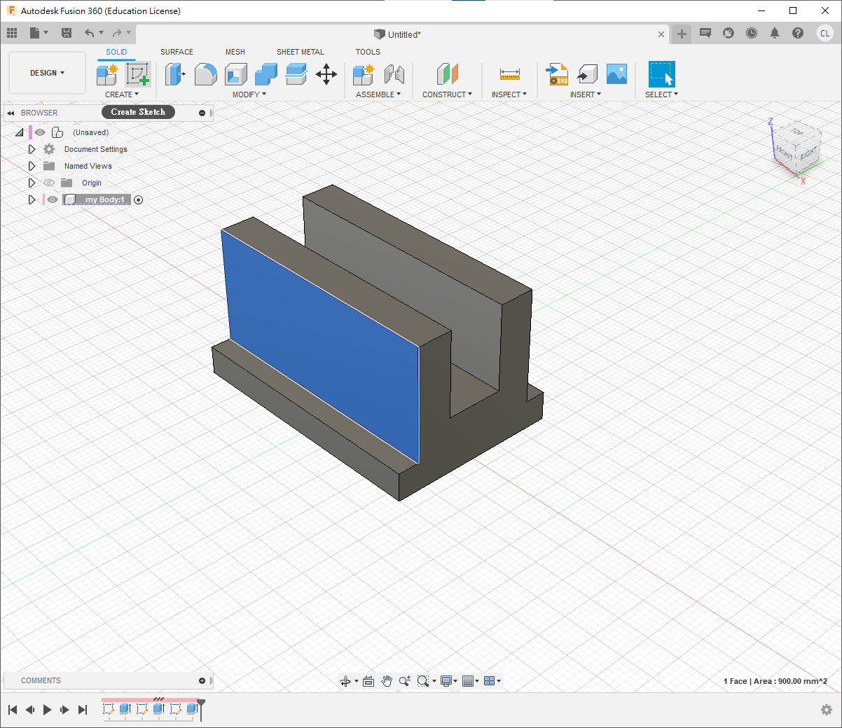
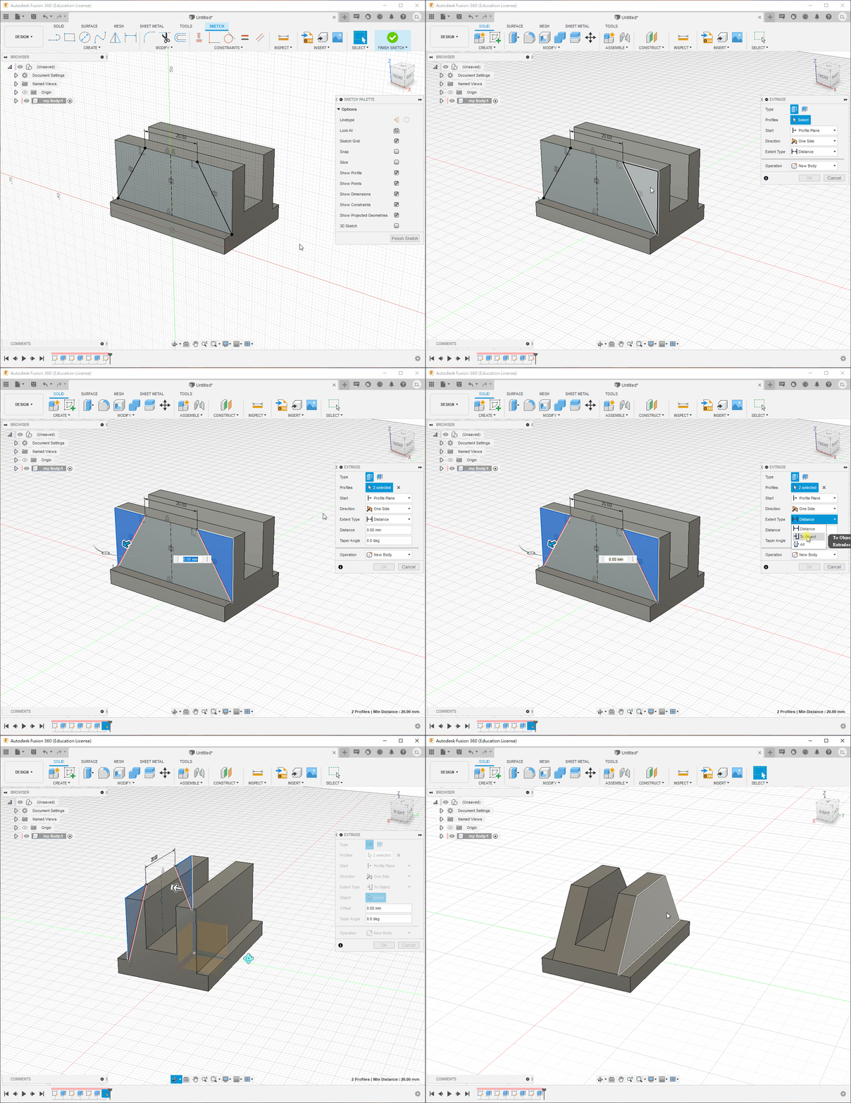
- Draw the two diagonal corner lines approximately and use the Symmetry constraint to make them symmetrical.
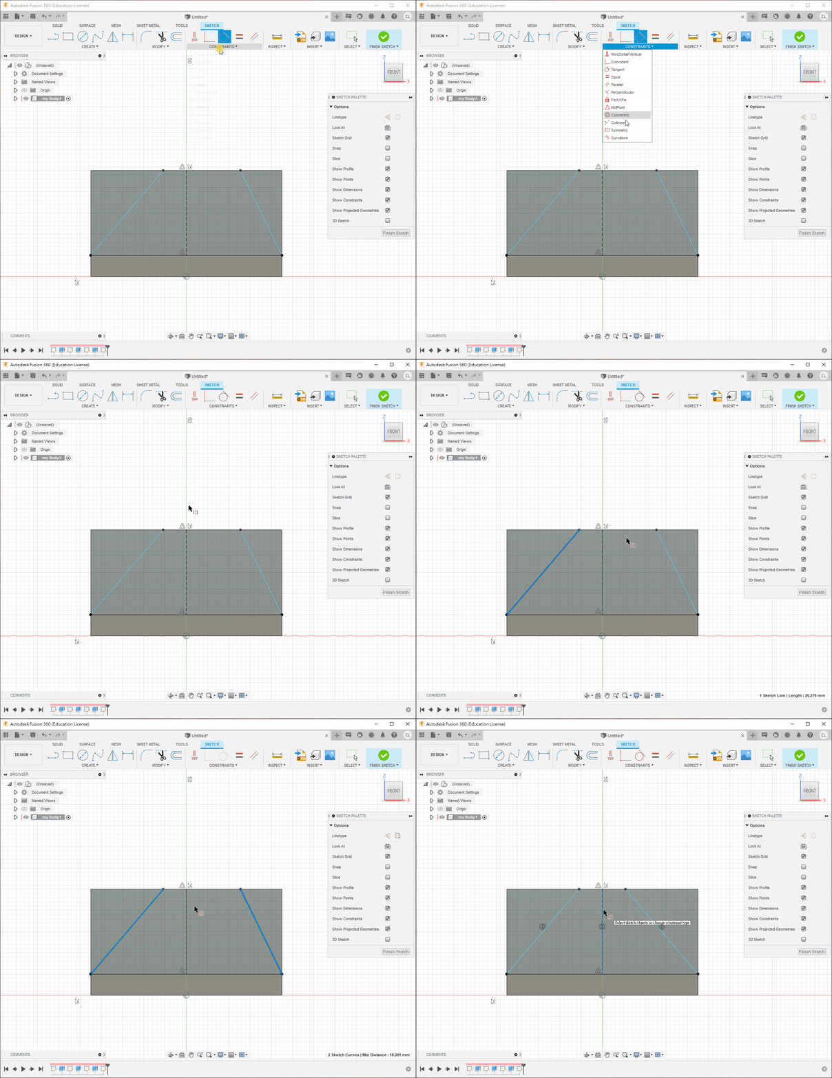
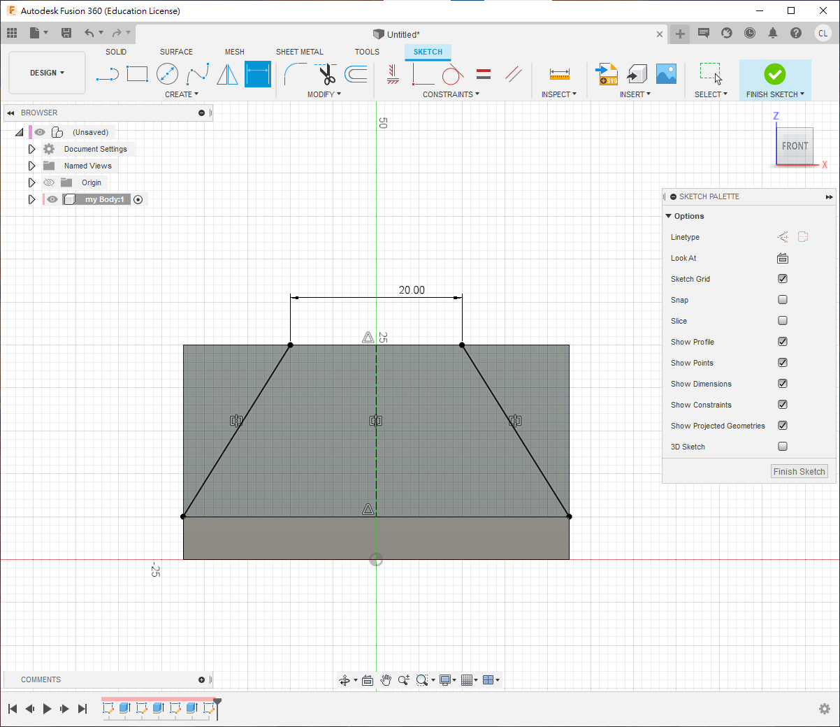
- Press
Eand remove the corners usingTo Object.
3. Exercises
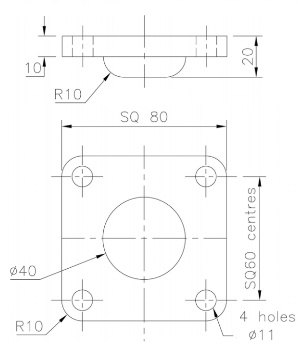
3.1
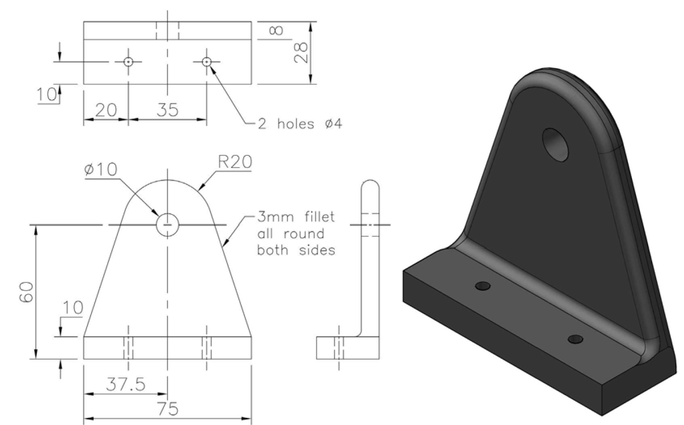
3.2
3.3
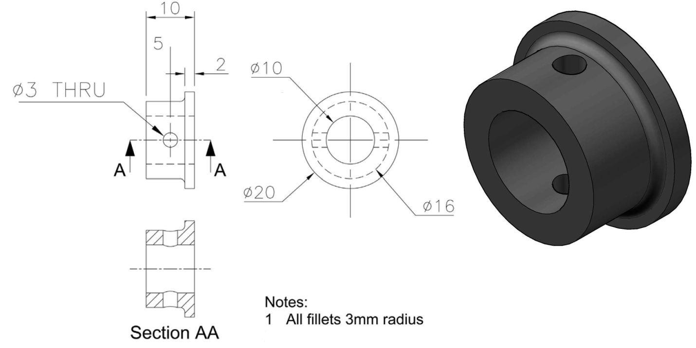
3.4
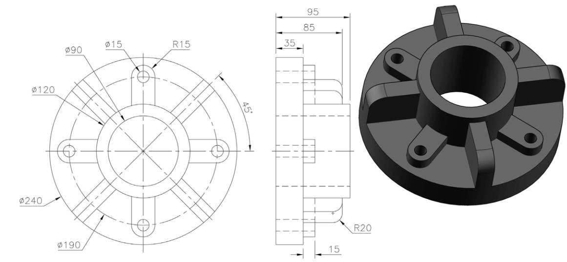
3.5
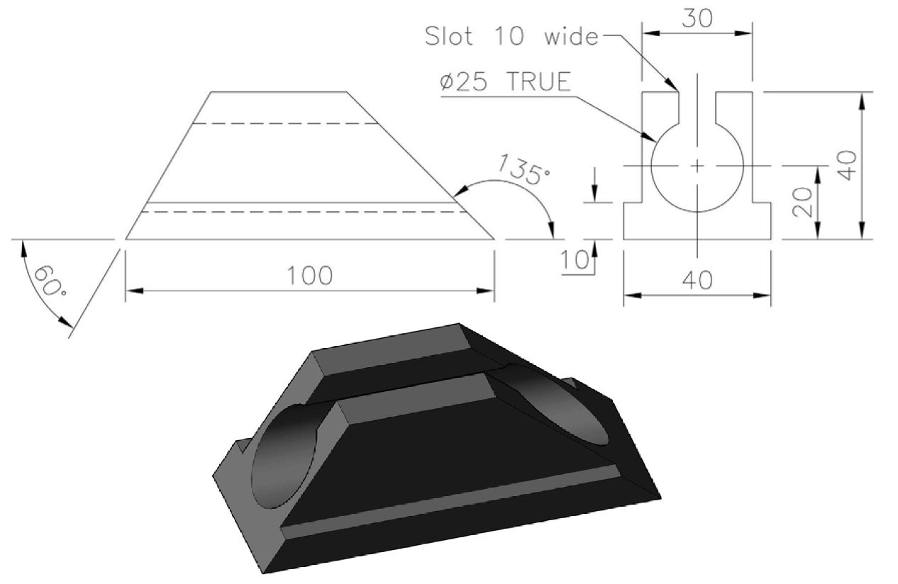
3.6
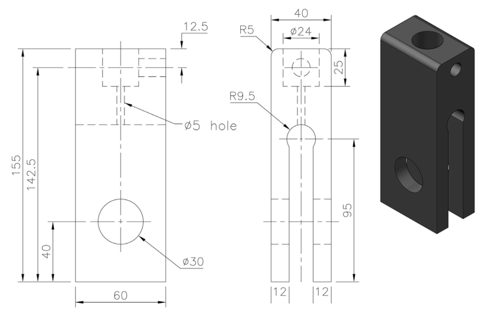
3.7
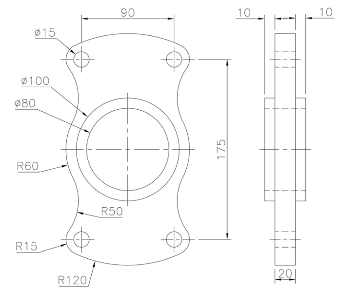
3.8
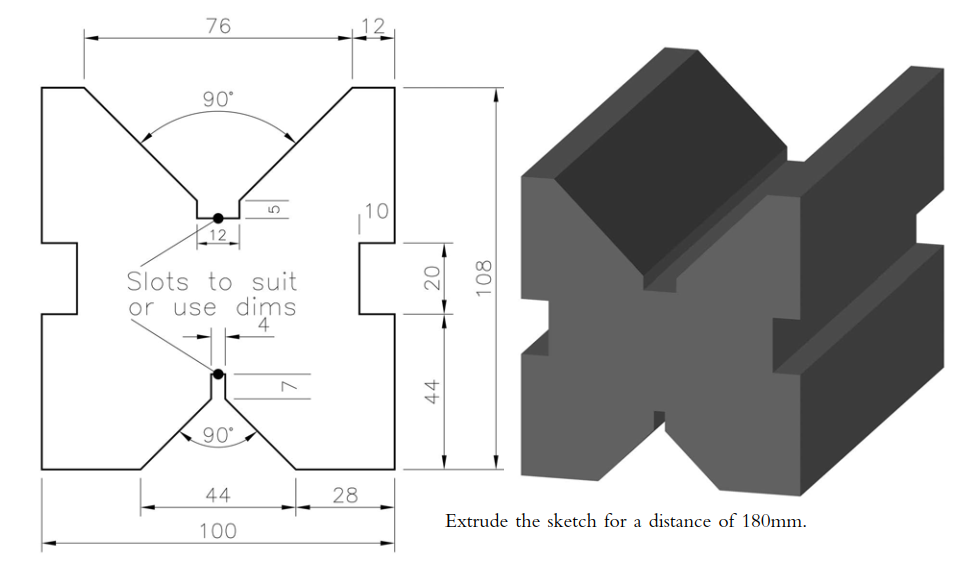
3.9
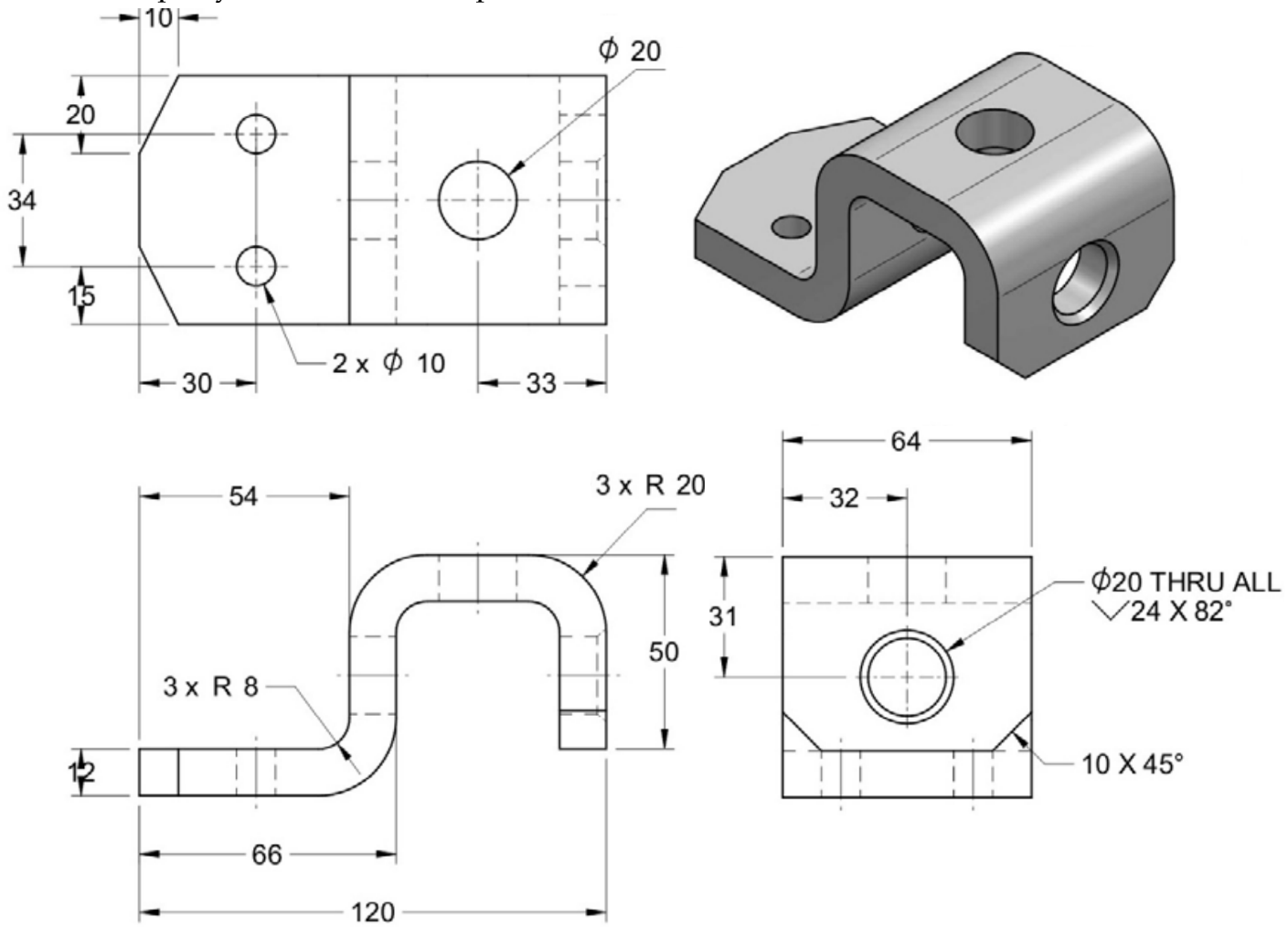
Hints
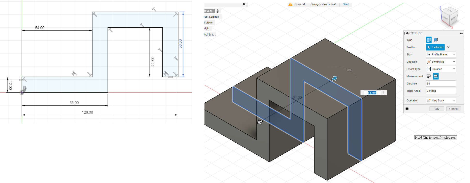
Ignore the fillets initially. Sketch the approximate side view, add the dimensions, and extrude it symmetrically.
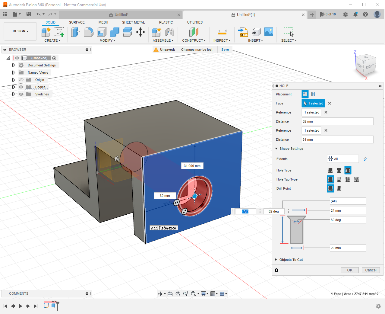
Ø20 THRU ALL ⌵24×82°specifies a 20 mm through-hole with a 24 mm, 82° countersink. Create it with theHolecommand:- Press
Hor selectHolefrom the menu. - Position the hole 32 mm from the left vertical edge and 31 mm from the upper horizontal edge.
- Set Hole Type to
Countersinkand the angle to82°. - Set Hole Tap Type to
Simple, since no thread is required. - Either drill-point option is acceptable because the hole passes through the part.
- Press
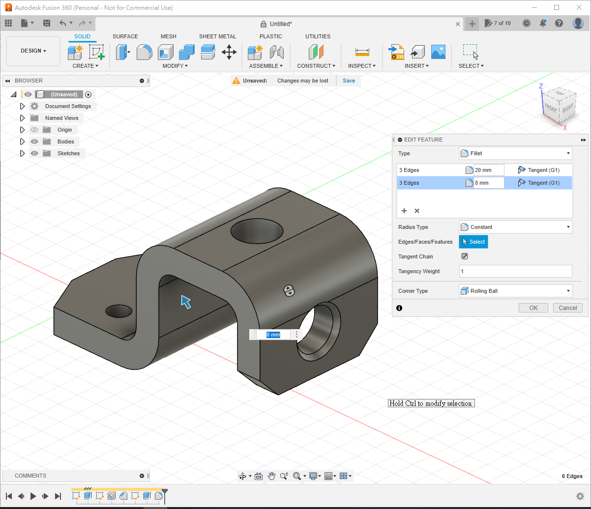
Finally:
- Sketch the remaining holes and remove them with Extrude, or use the Hole command.
- Use Chamfer on the bevelled corners.
- Use Fillet on the rounded corners.
Translation notice: This English page was generated automatically by AI and has not yet been reviewed by a human. It will be checked and revised page by page when time permits.