Advanced Box
ℹ️INFO
Large enclosures made only from thin plastic sheet can break apart easily. Thicker sheet is heavier and harder to machine. A modular aluminium-extrusion frame provides a rigid internal structure while allowing thinner panels.
Files
Download and extract the STEP models, then use Upload in Fusion's Data Panel to import them.
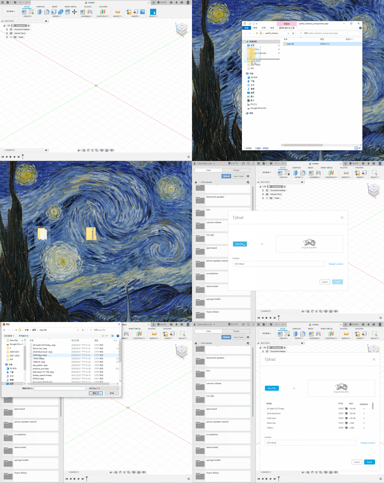
1. Create the Six Panels
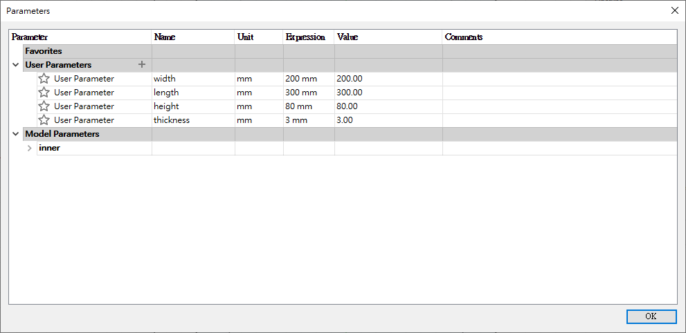
Create the six panels by following Sections 1 and 2 of the Simple Box chapter. Open Change Parameters and set the internal length, width and height to the values shown.
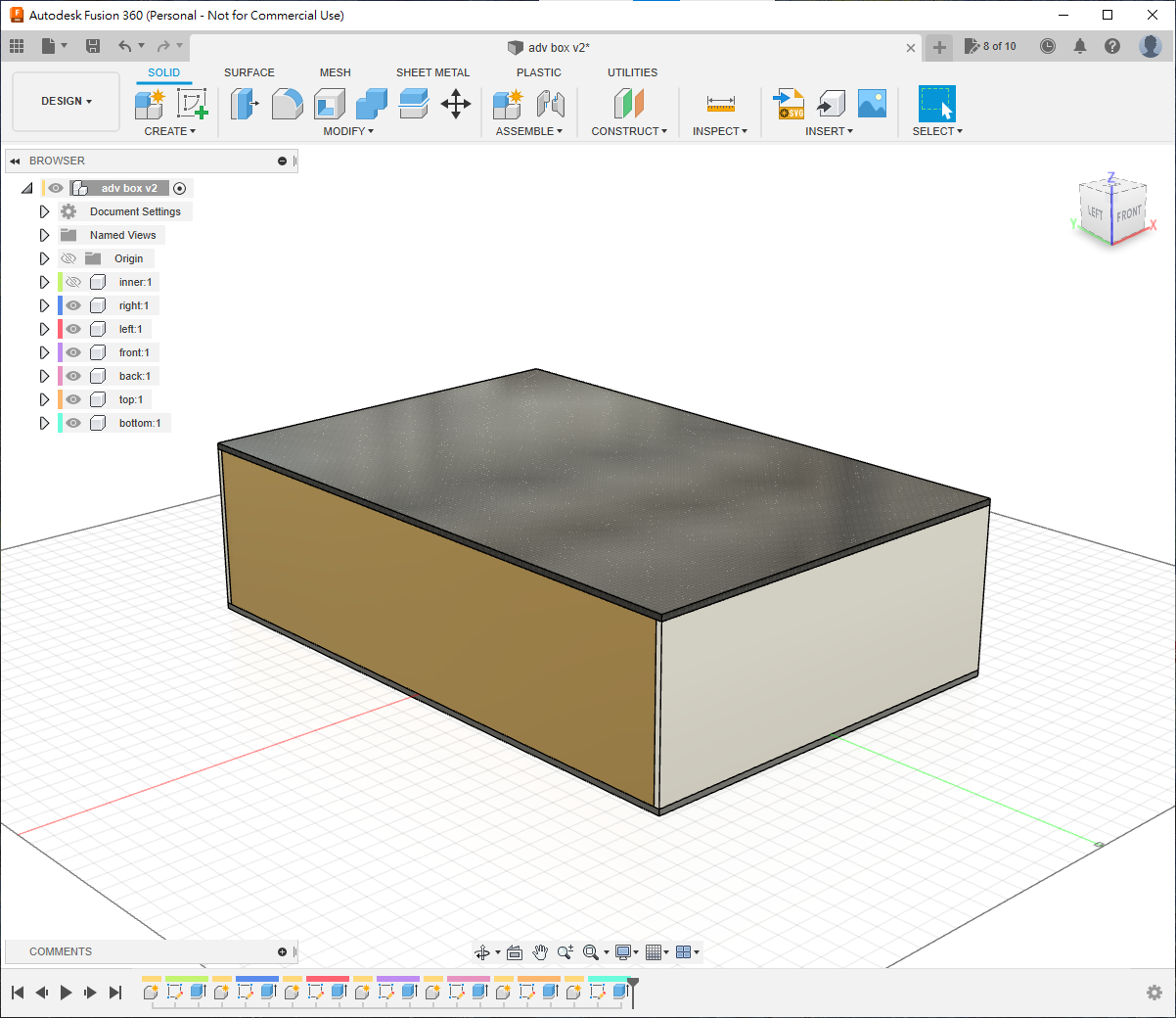
2. Create the Aluminium Frame
About Aluminium Extrusion
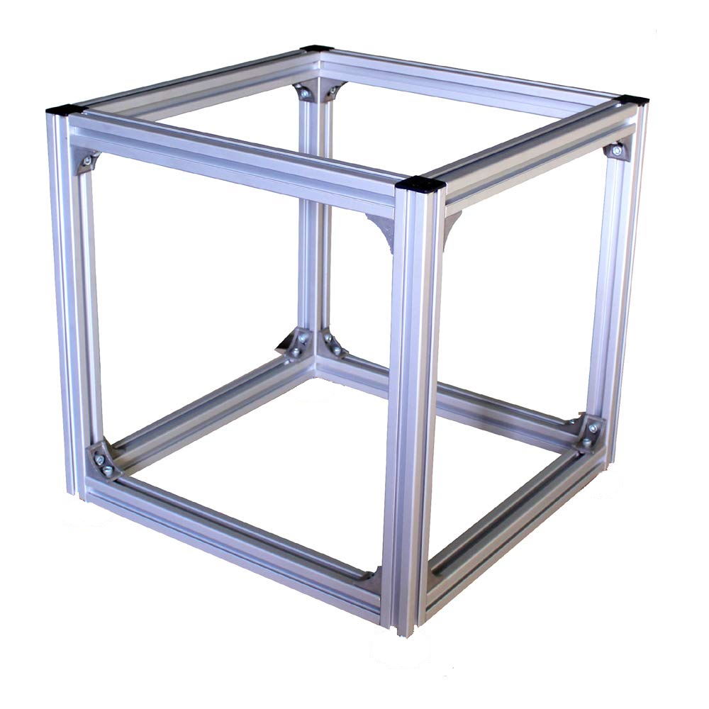
Two common connection methods are:
External triangular brackets: strong and well suited to large loaded structures, but remain visible.
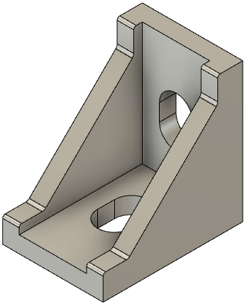 [Reference model](https://grabcad.com/library/aluminium-corner-bracket-2028-1)
 Internal L-connectors: hidden inside the extrusion slots for a cleaner appearance.

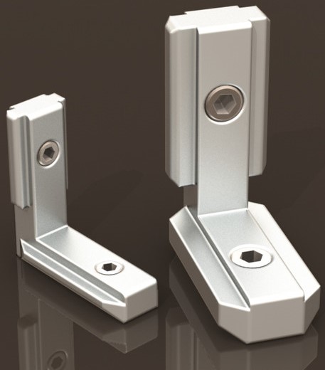
A rectangular frame uses 12 extrusions in three lengths corresponding to the enclosure's length, width and height. Because each extrusion has finite width, those lengths depend on the assembly order and are not always equal to the enclosure dimensions. Plastic panels are normally fixed to 2020 extrusion slots with M5 screws and T-nuts.
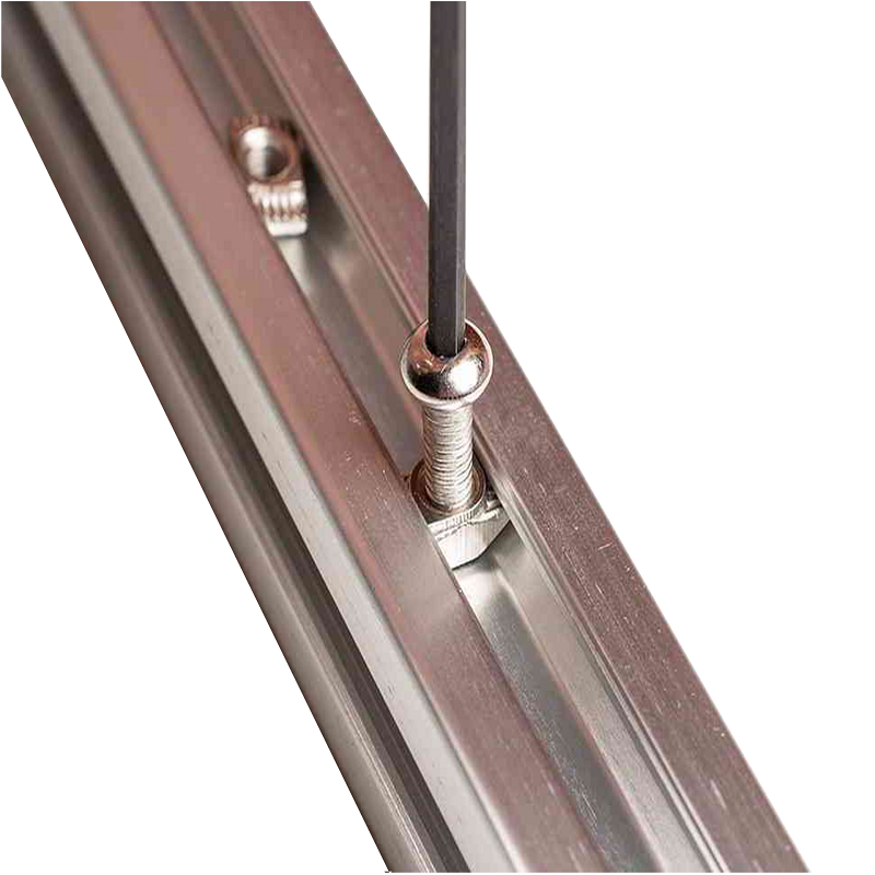
Lengthwise Extrusions
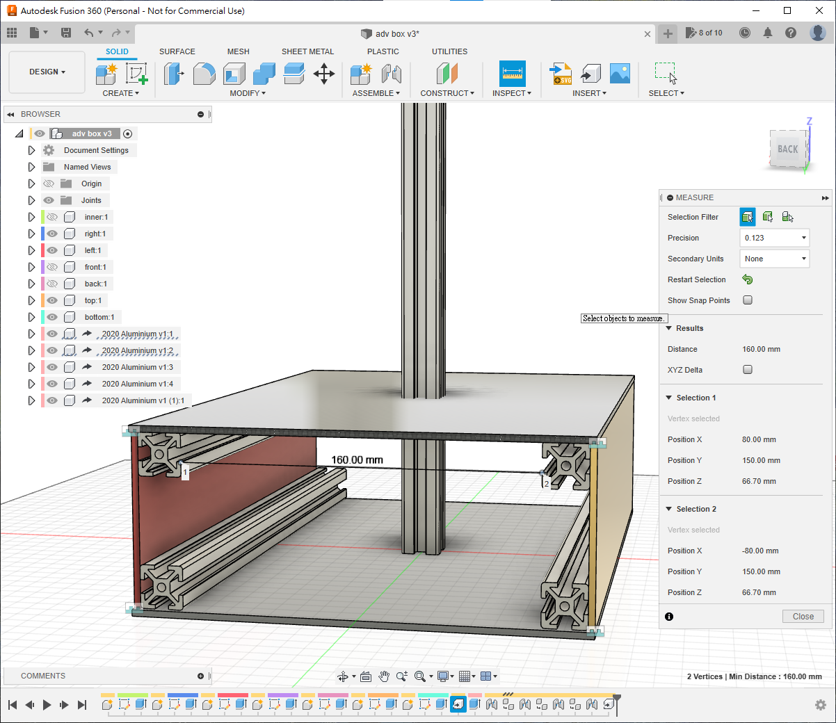
Hide the left component and press I to measure the 300 mm internal length.
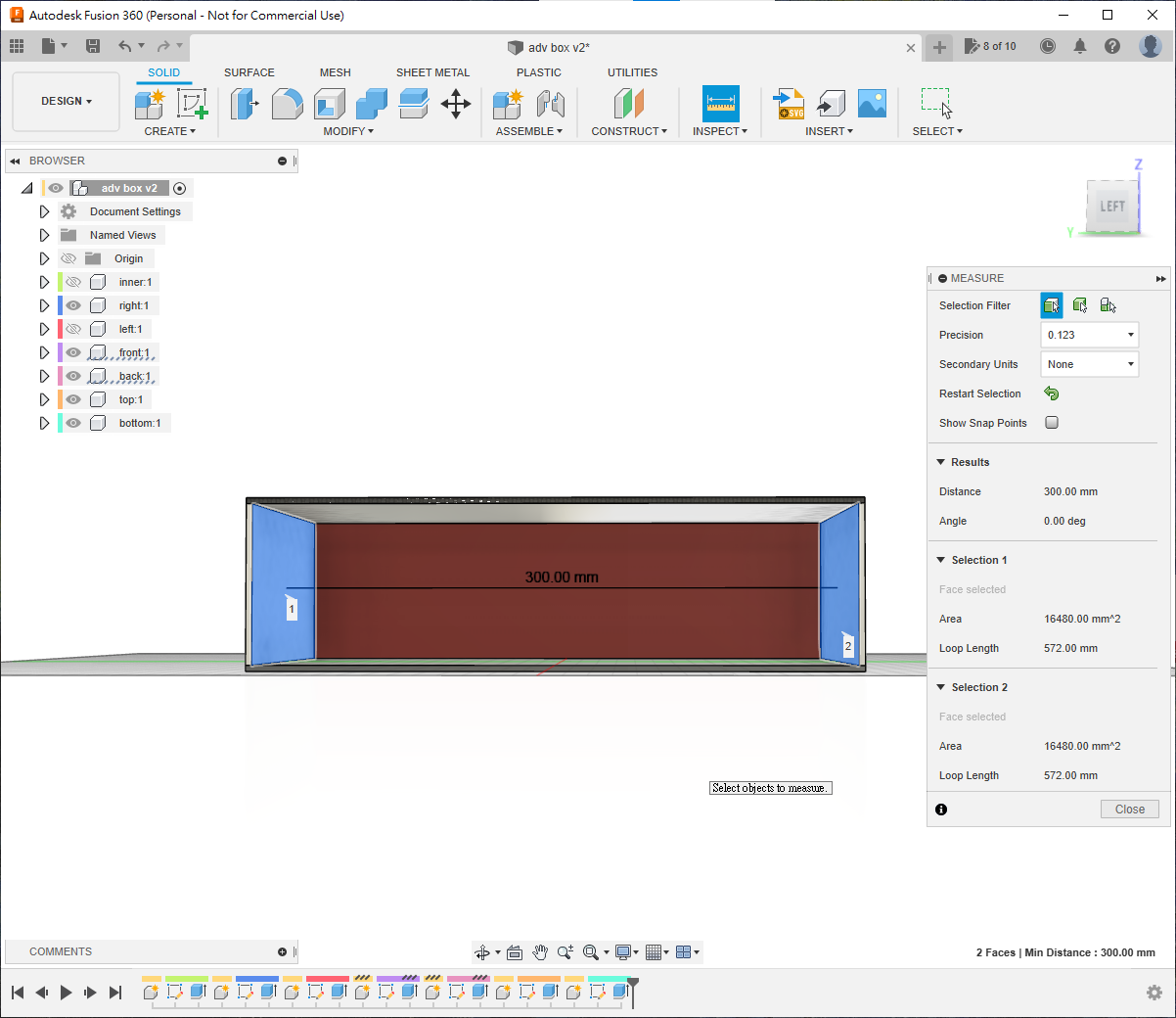
Use Insert Derive to bring the complete extrusion into the design as a component.
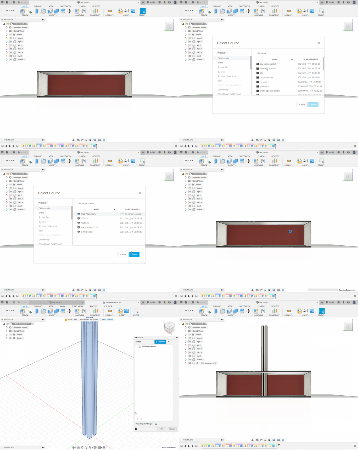
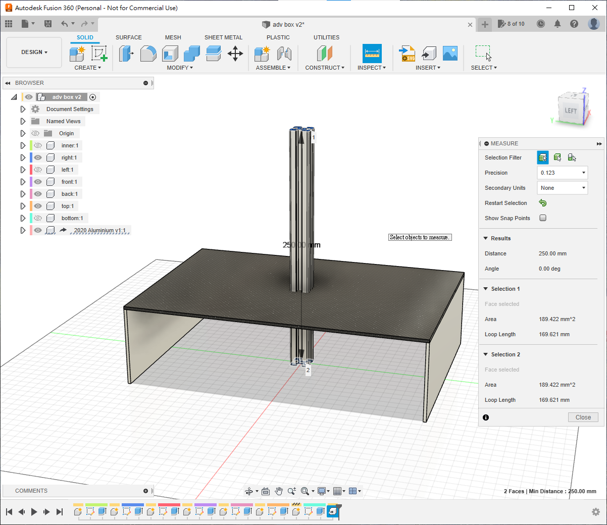
Measure the imported part. It is 250 mm, so it must be extended by 50 mm.
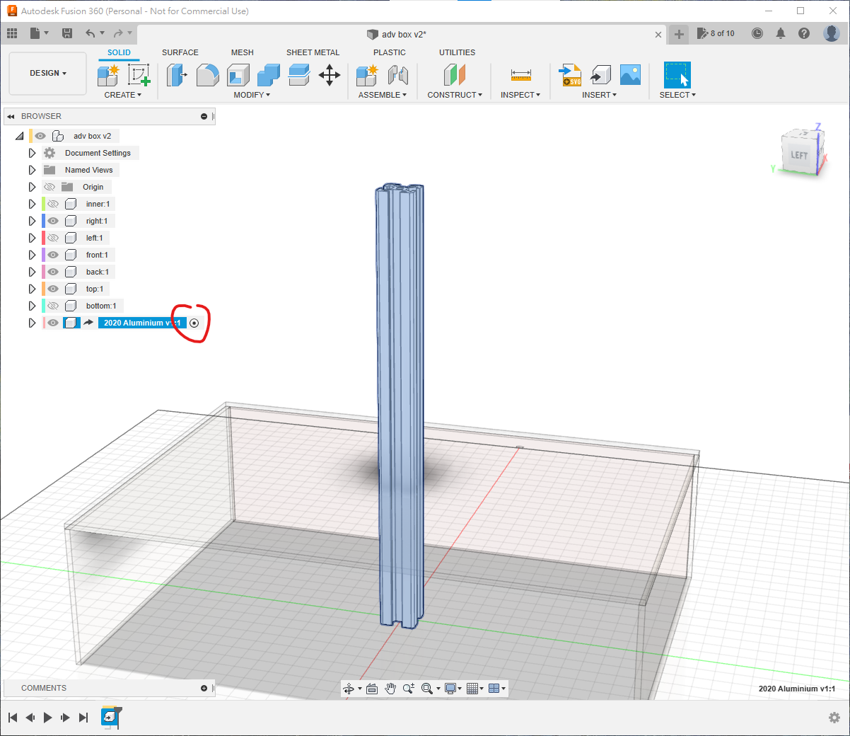
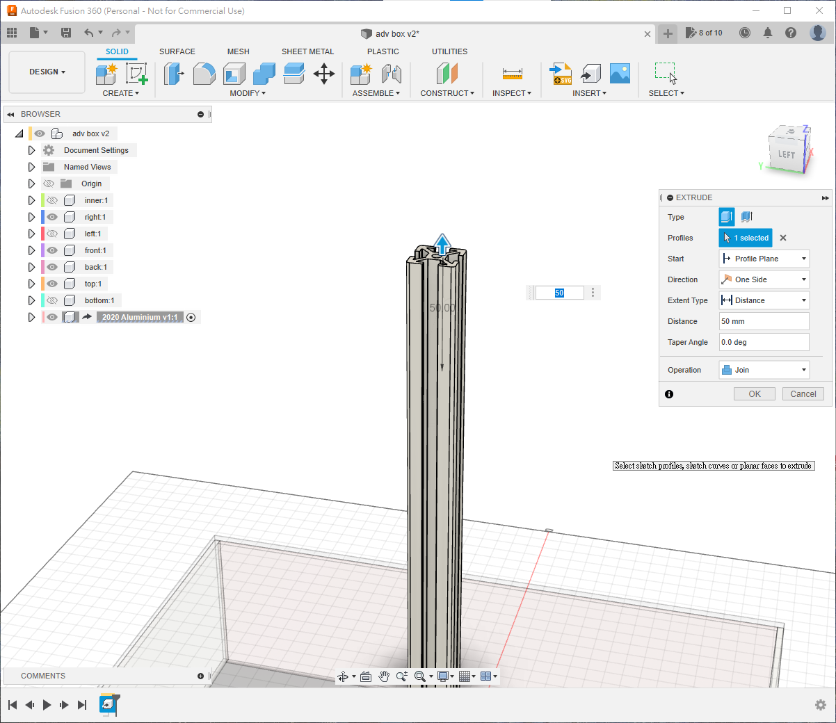
Activate the extrusion component and press E to extend its end face by 50 mm; no additional sketch is required.
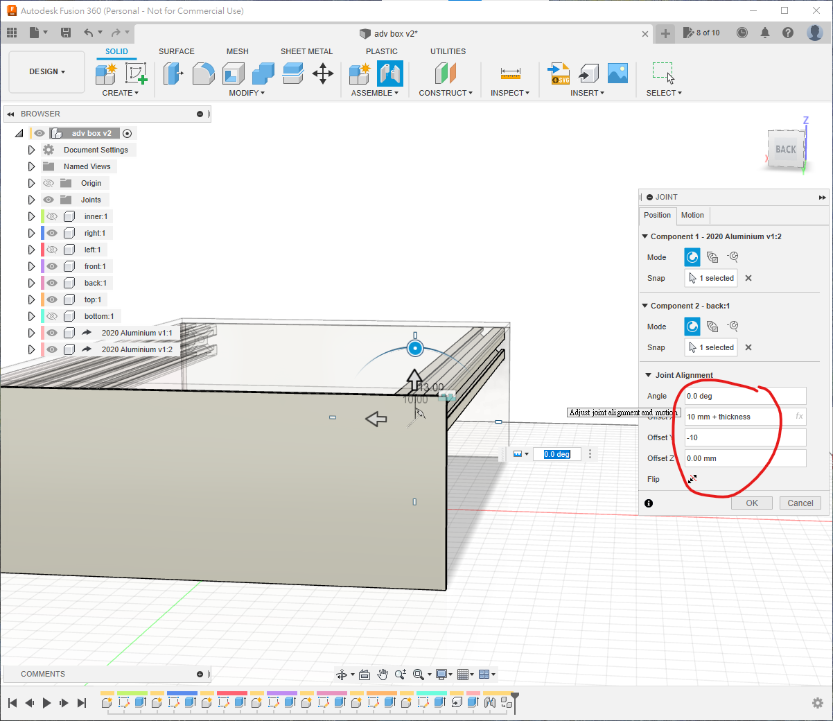
Reactivate the top level. Press J, select the extrusion's central hole and the inside corner of back. Use approximately X = -10 mm - thickness and Y = -10 mm so that the extrusion sits just inside the enclosure. Axis names and signs may differ according to selection order.
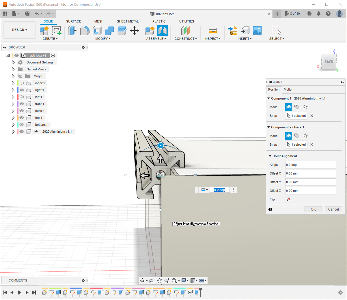
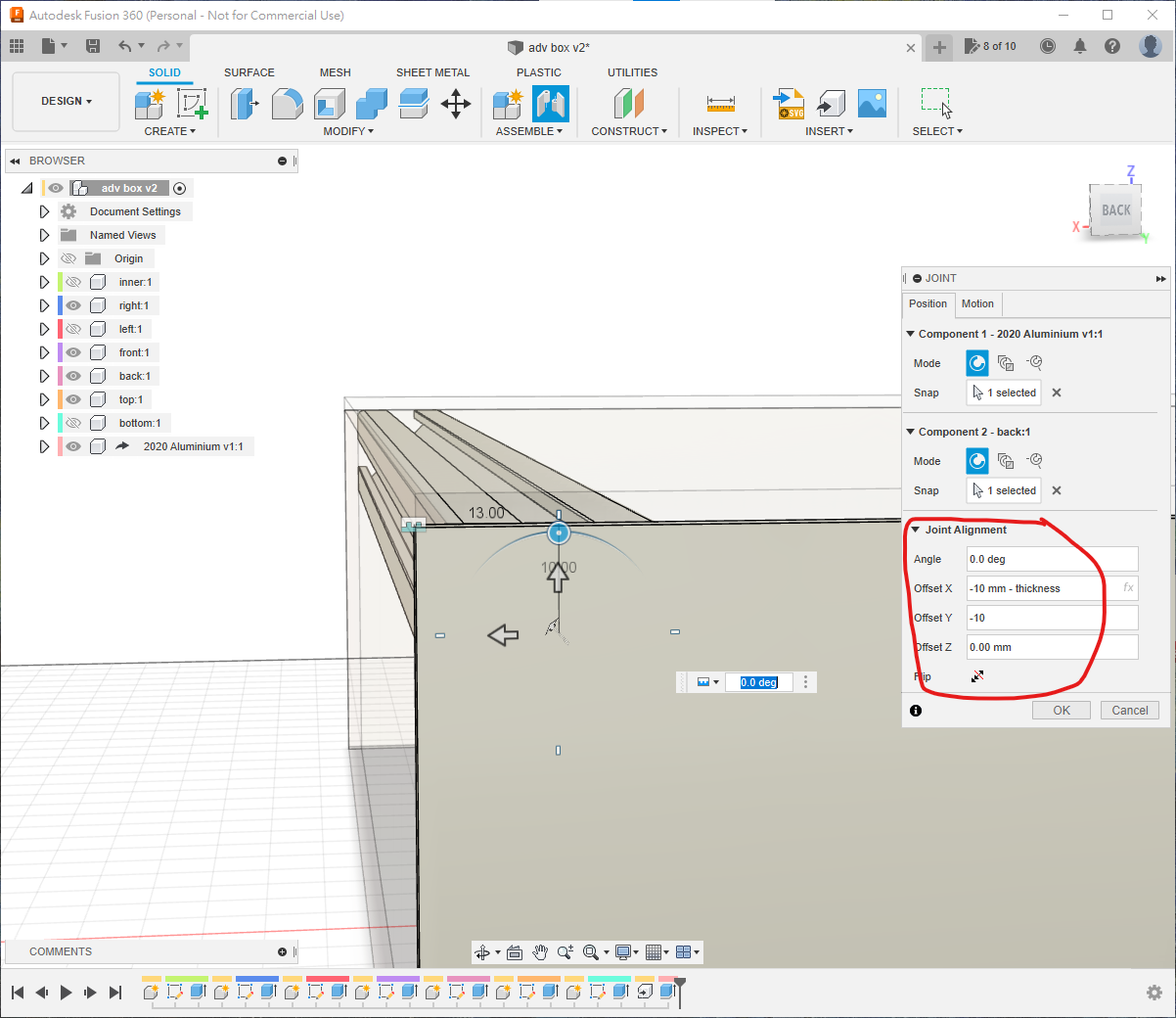
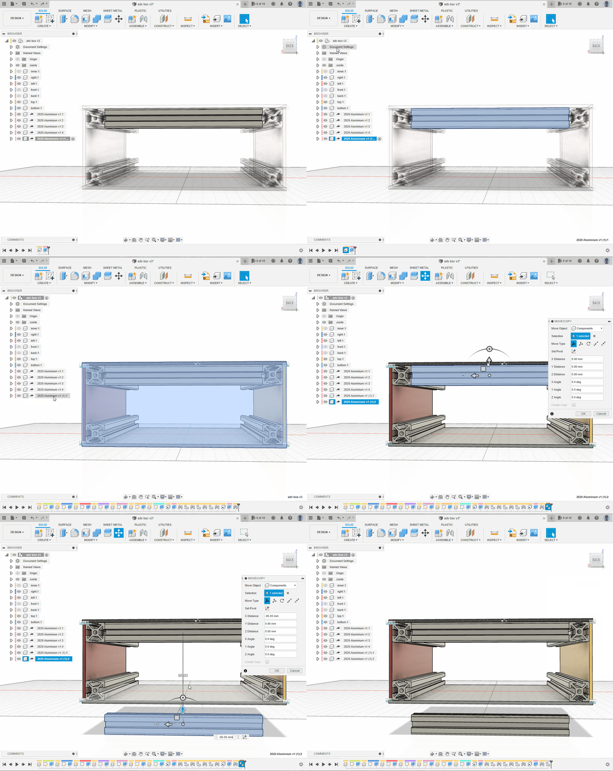
At the top level, select 2020 Aluminium v1:1, copy with Ctrl-C and paste with Ctrl-V.
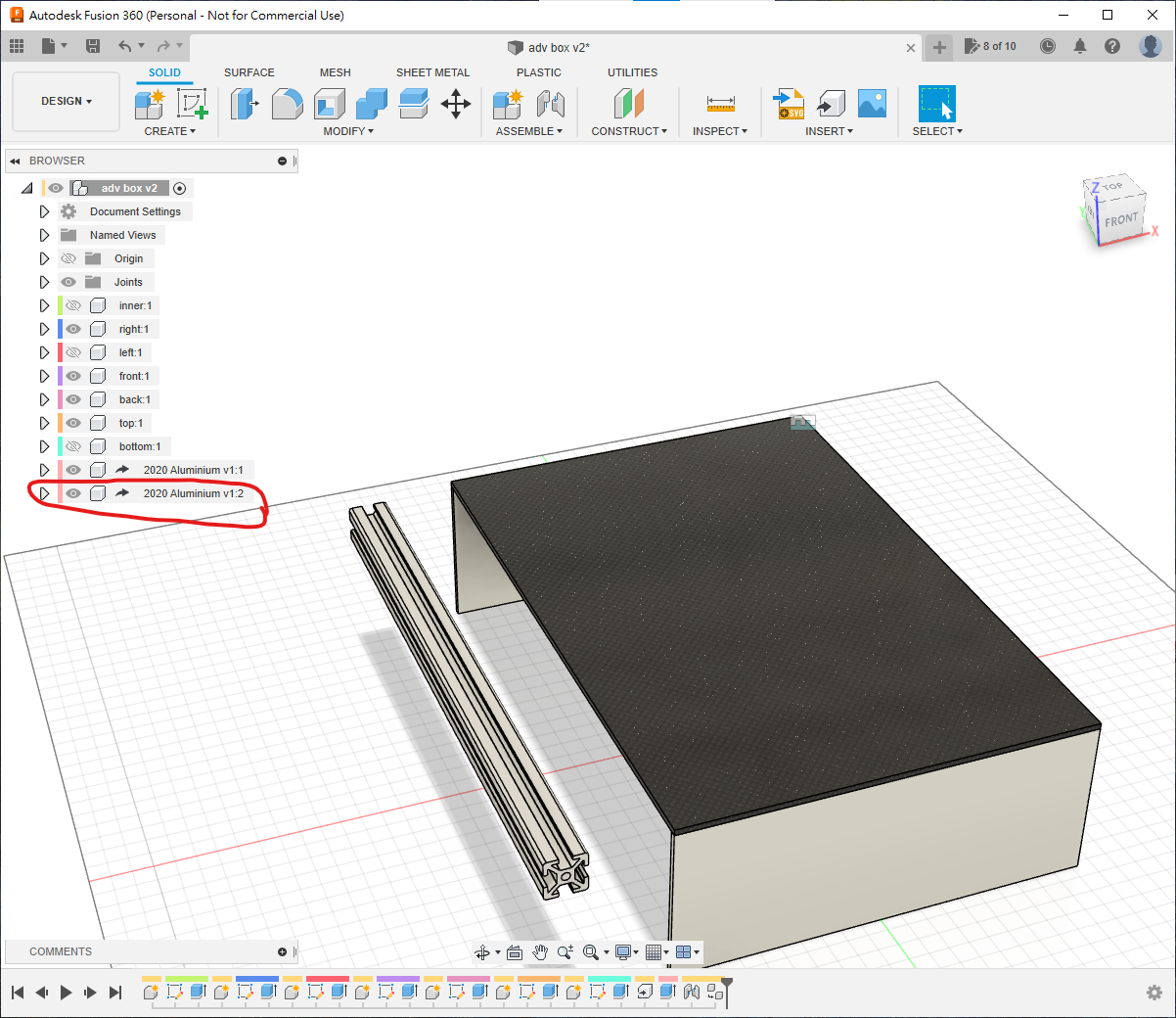
Joint the copy on the opposite side, then repeat until four lengthwise extrusions are installed.
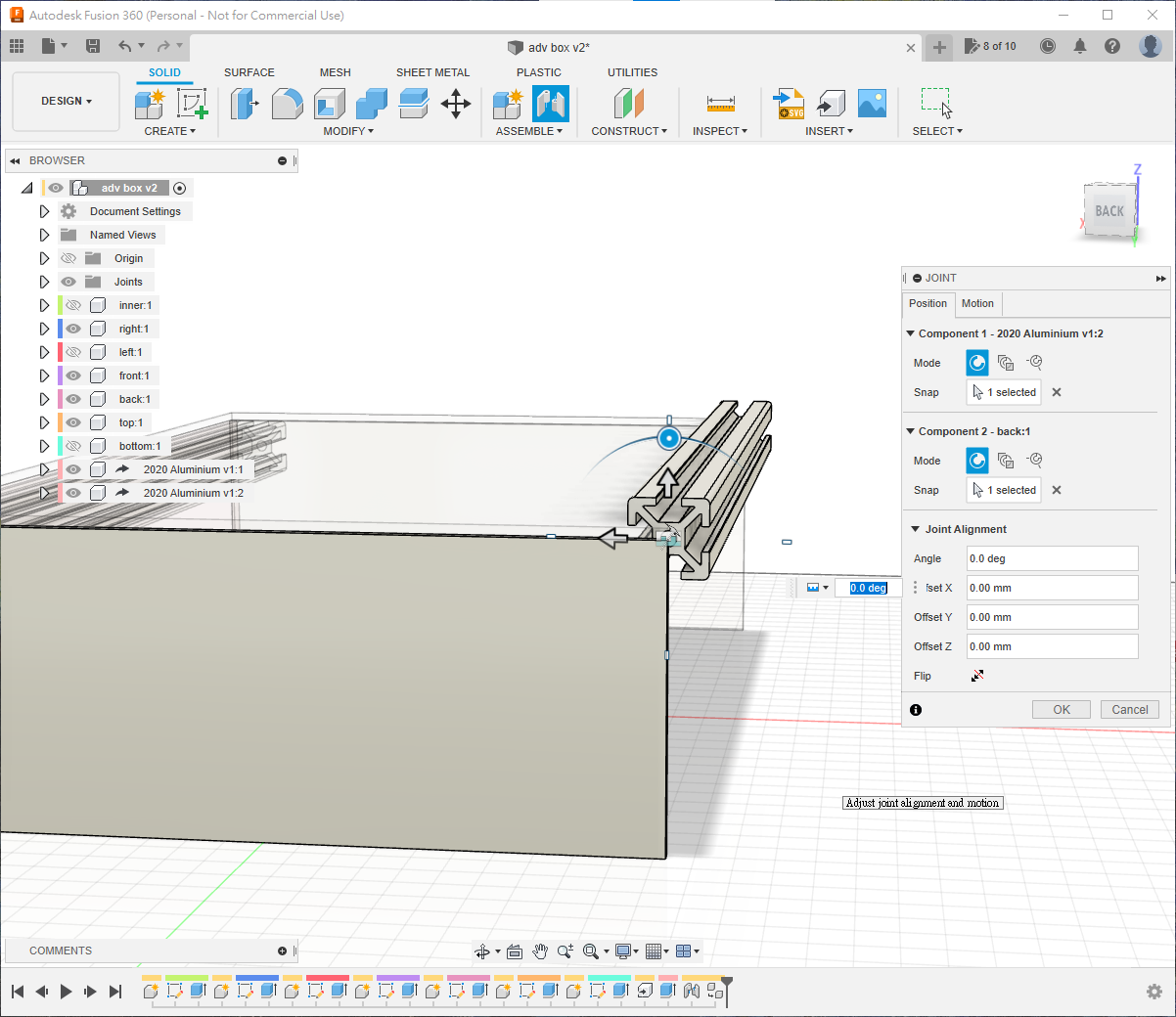
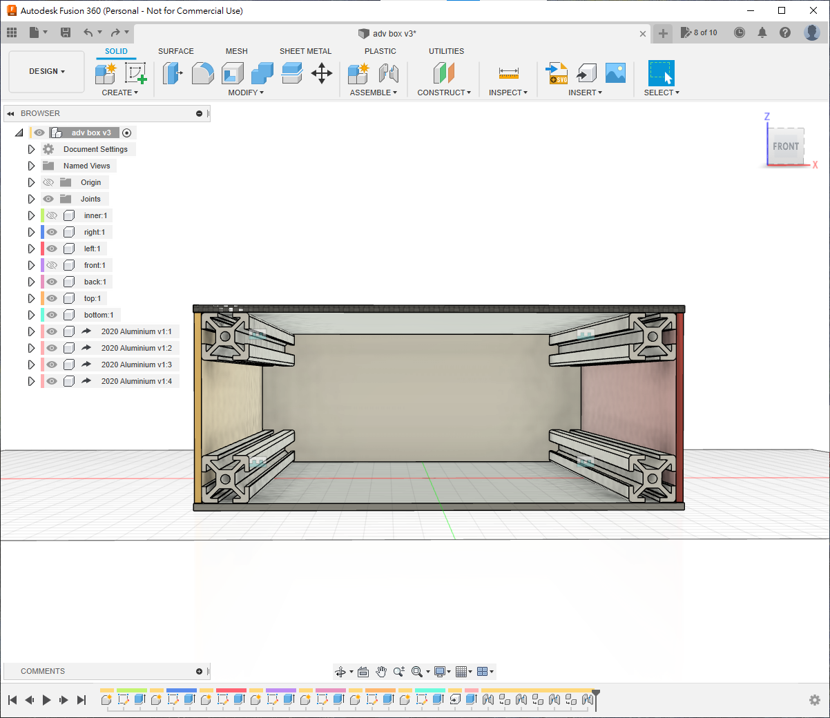
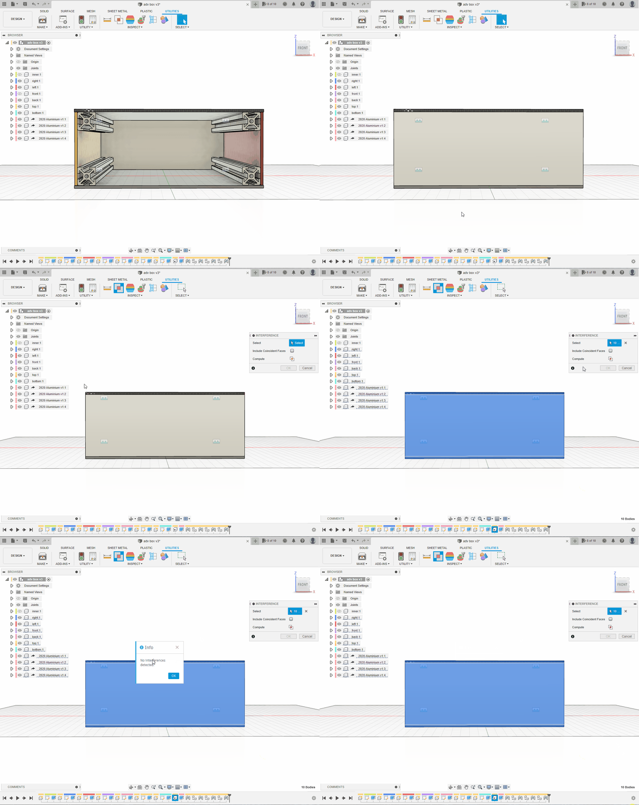
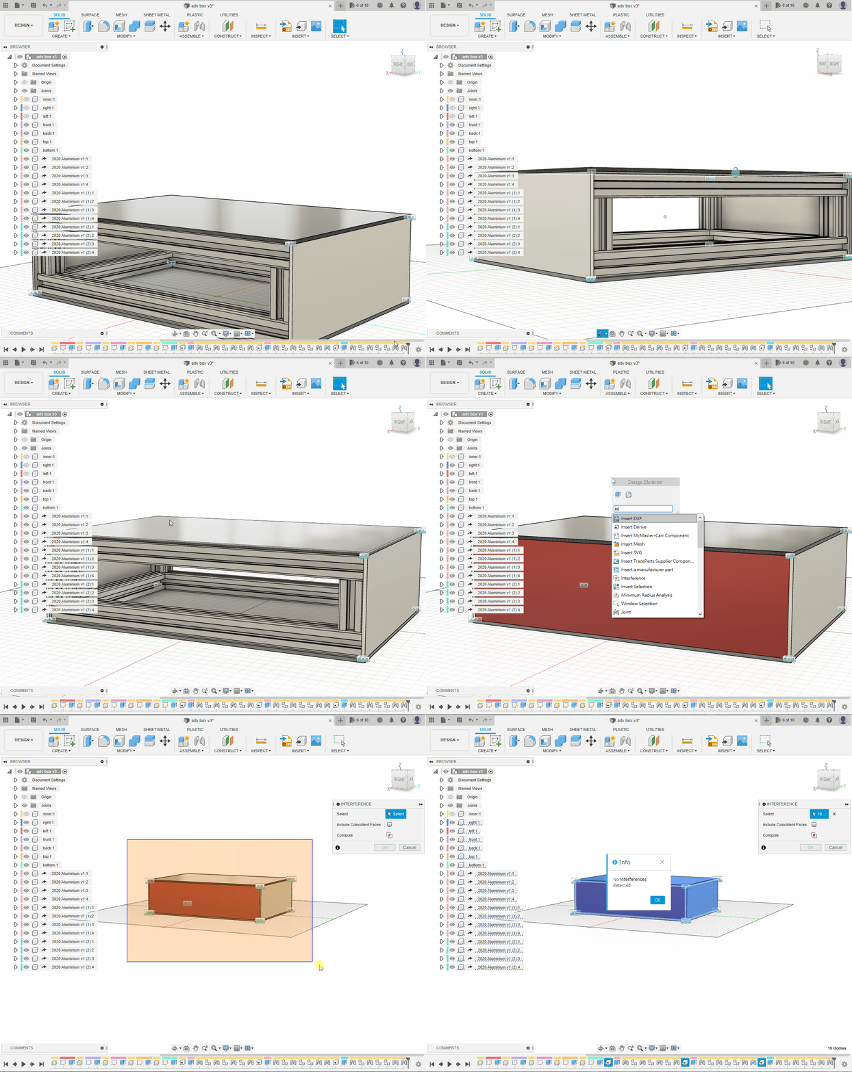
Show all six panels and run Interference to check that no parts overlap because of an incorrect joint.
Widthwise Extrusions
Use Insert Derive to import a fresh, unmodified extrusion as a separate component.
⚠️WARNING
Do not copy the lengthwise component: copied occurrences share the same definition, so editing one would change every copy to the same length.
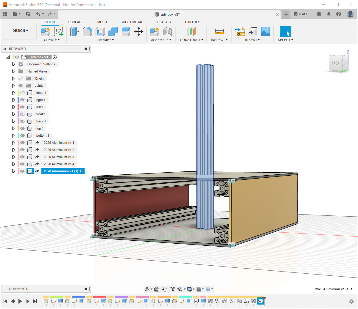
The enclosure is 200 mm wide. Subtract two 20 mm extrusions, leaving 160 mm; shorten the original 250 mm extrusion by 90 mm.
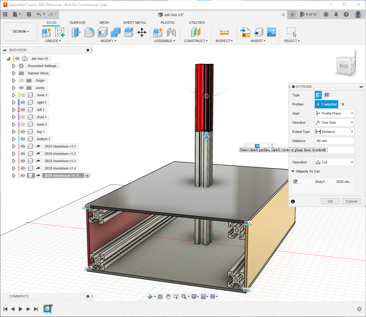
Because the rounded edges do not provide a centreline, joint the extrusion's central hole to the corner of the right panel. Use approximately X = -10 mm, Y = -10 mm, Z = 20 mm, adjusting signs for your selection order.
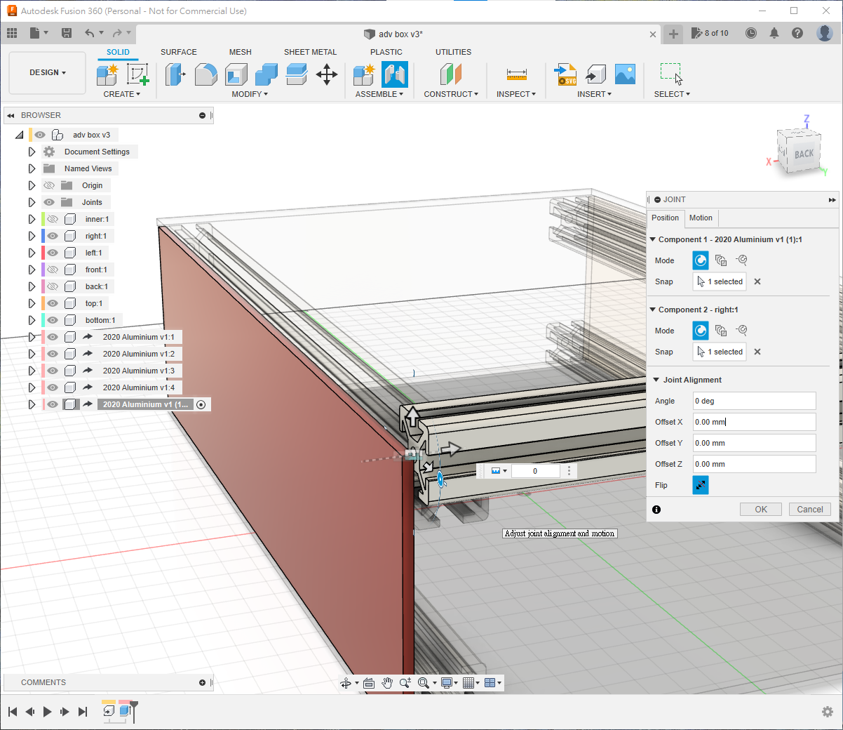
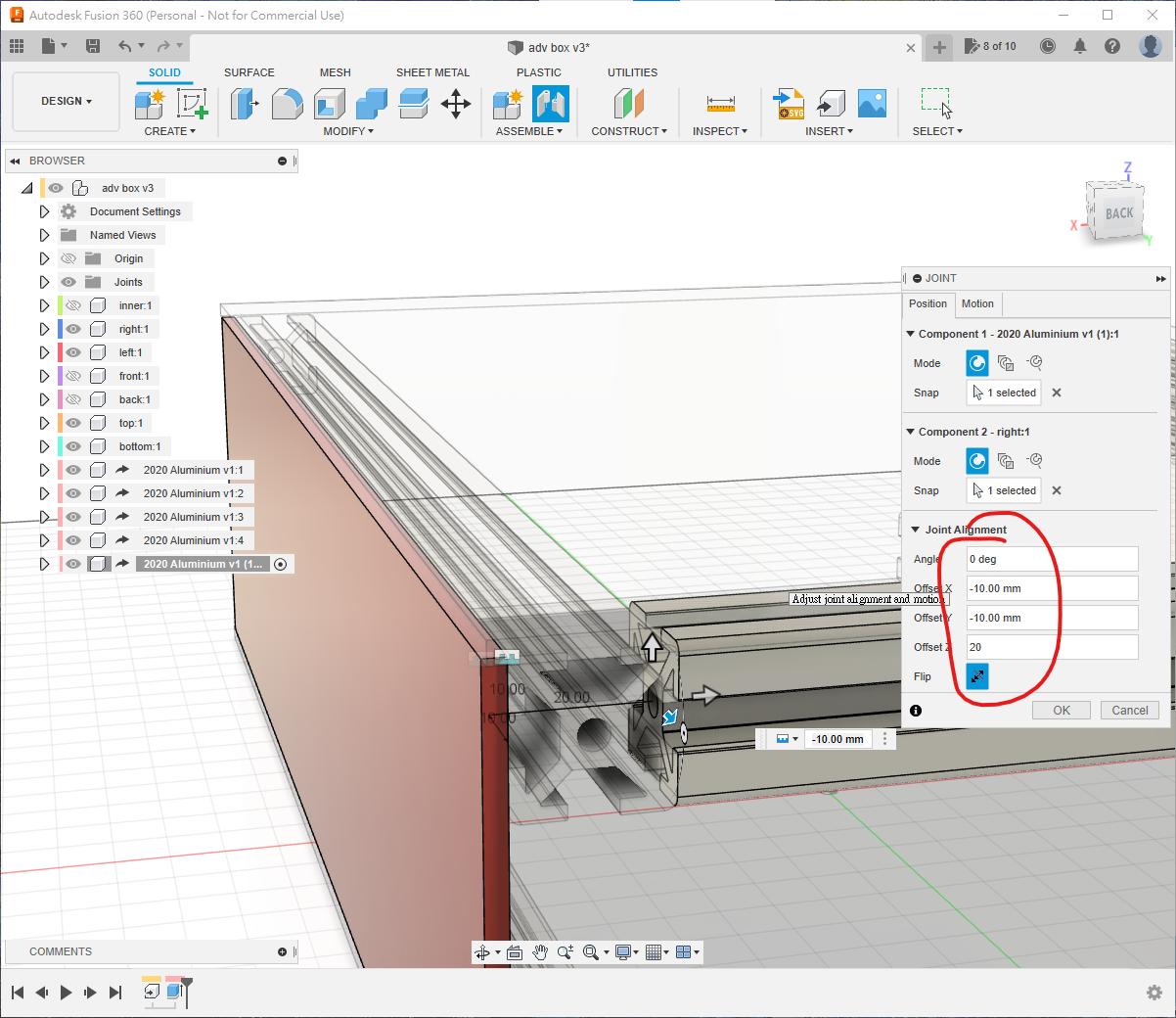
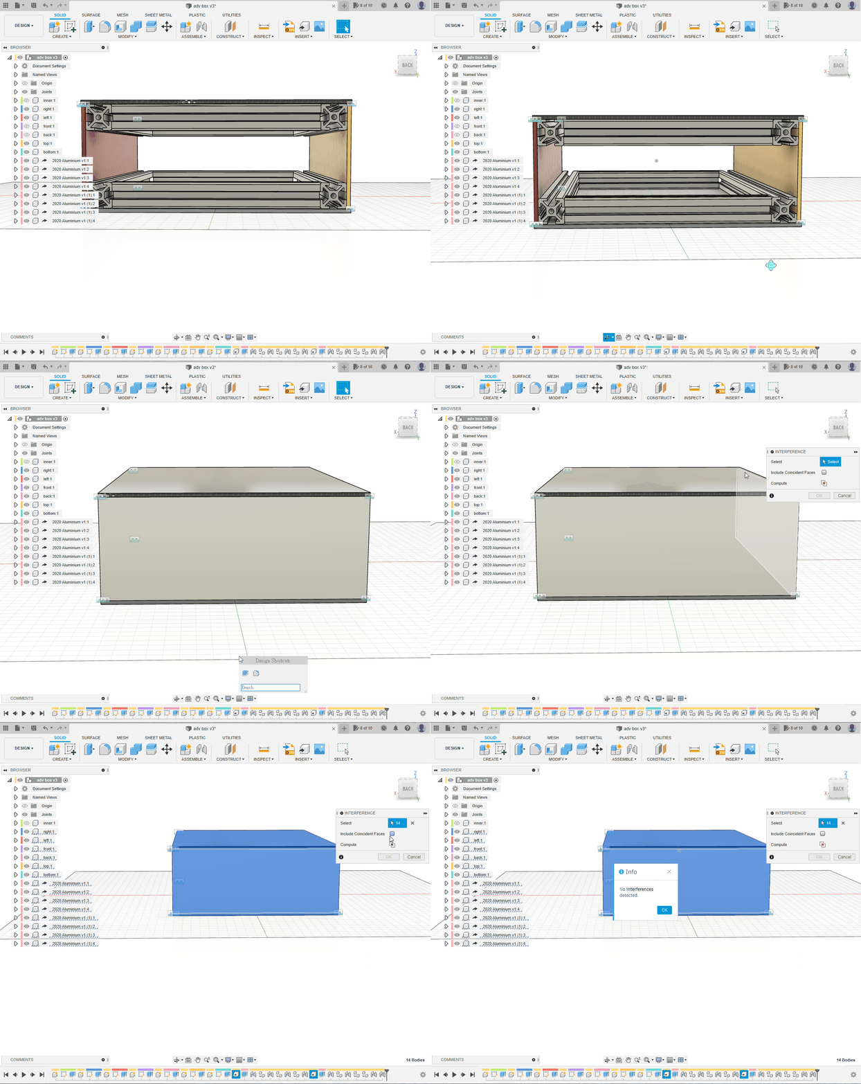
At the top level, copy this component three times and create four joints in total.
Show all components and run Interference again.
Vertical Extrusions
Derive a third fresh extrusion component.
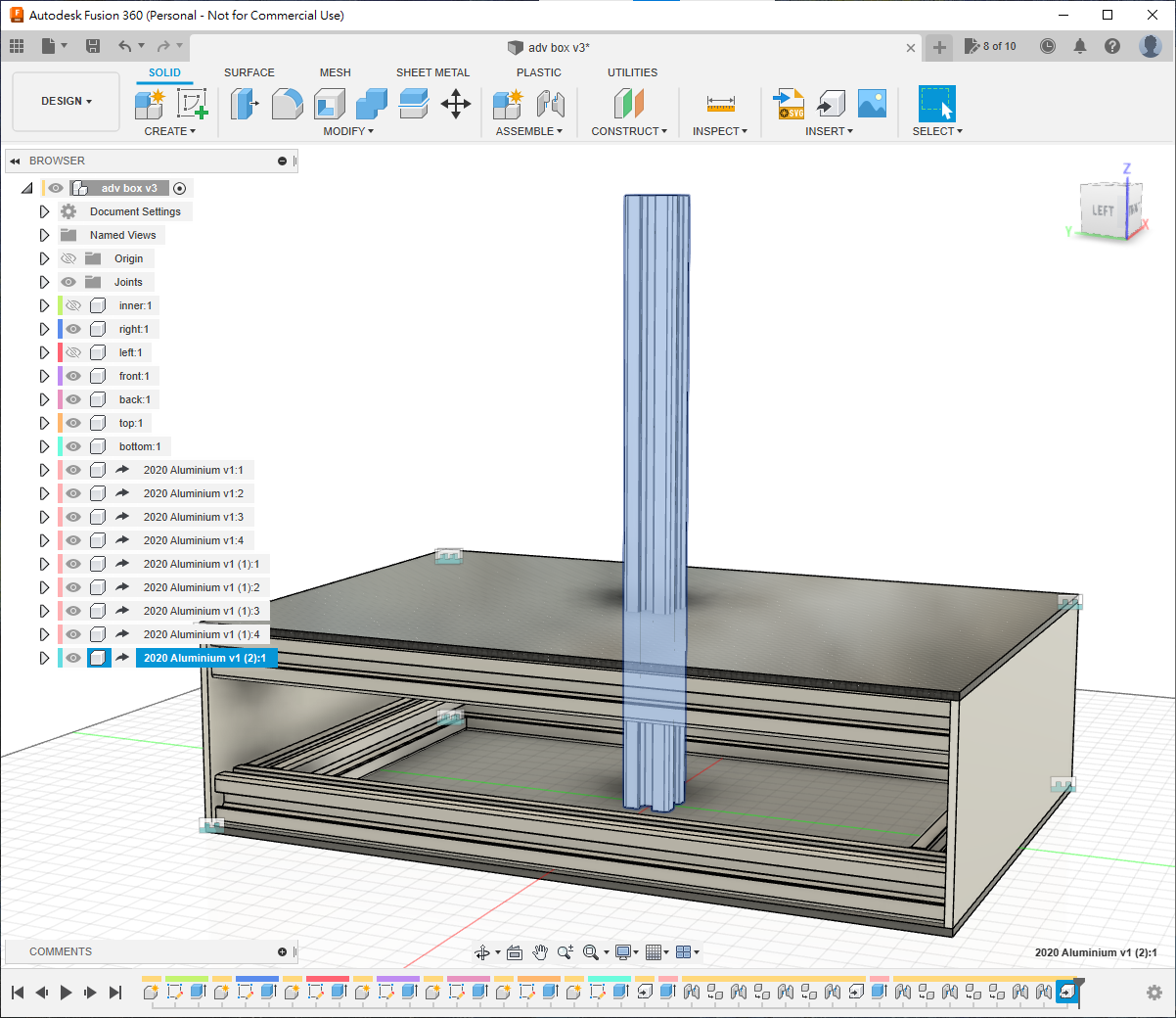
The enclosure is 80 mm high. After subtracting the two 20 mm horizontal members, each vertical extrusion is 40 mm; shorten the 250 mm source by 210 mm. Activate the component and press E. If other bodies are affected, restrict Objects to Cut to the current component or hide the others first.
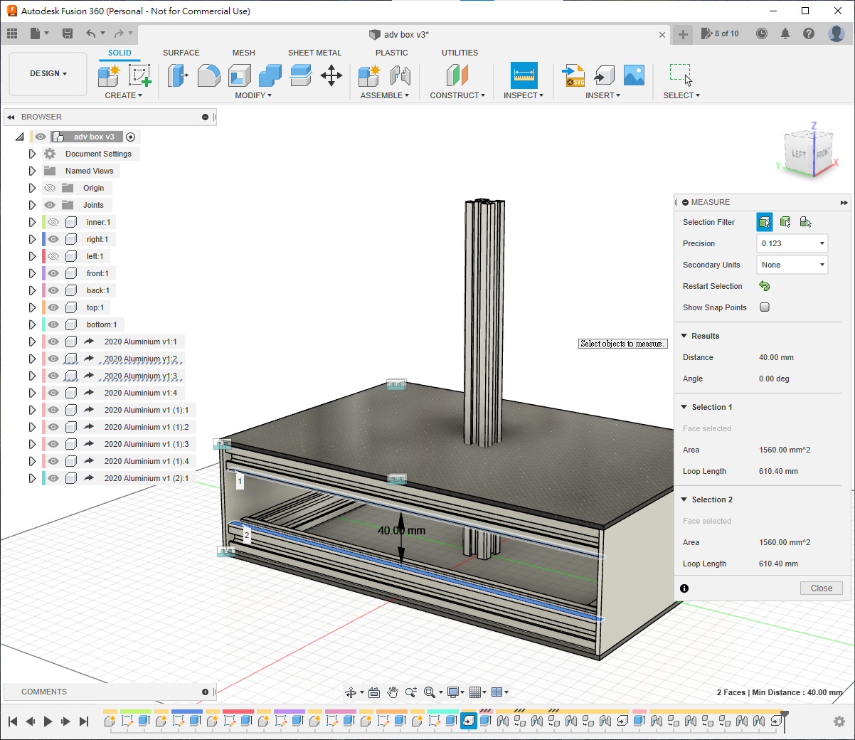
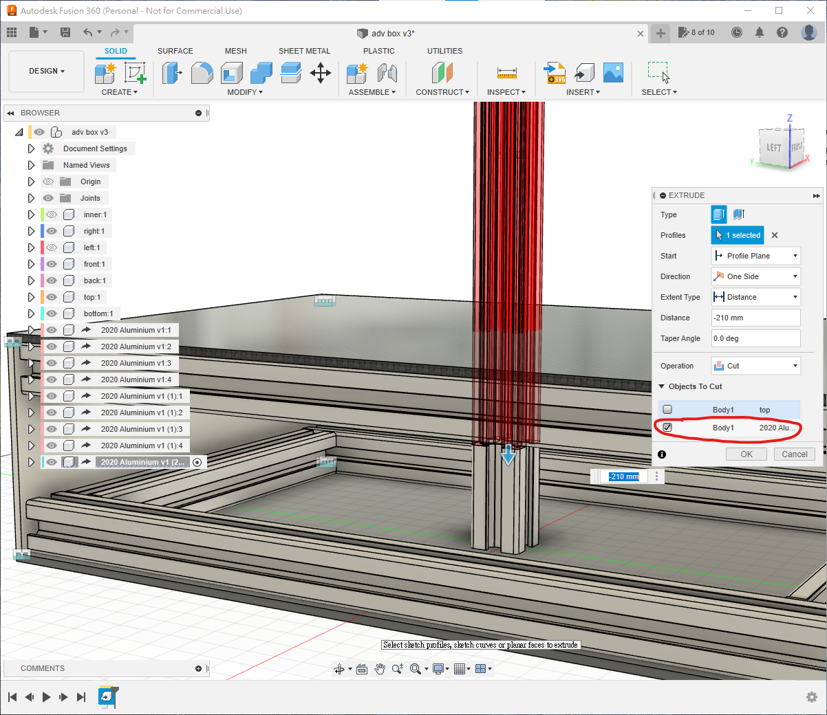
Joint it underneath the top panel using the offsets shown.
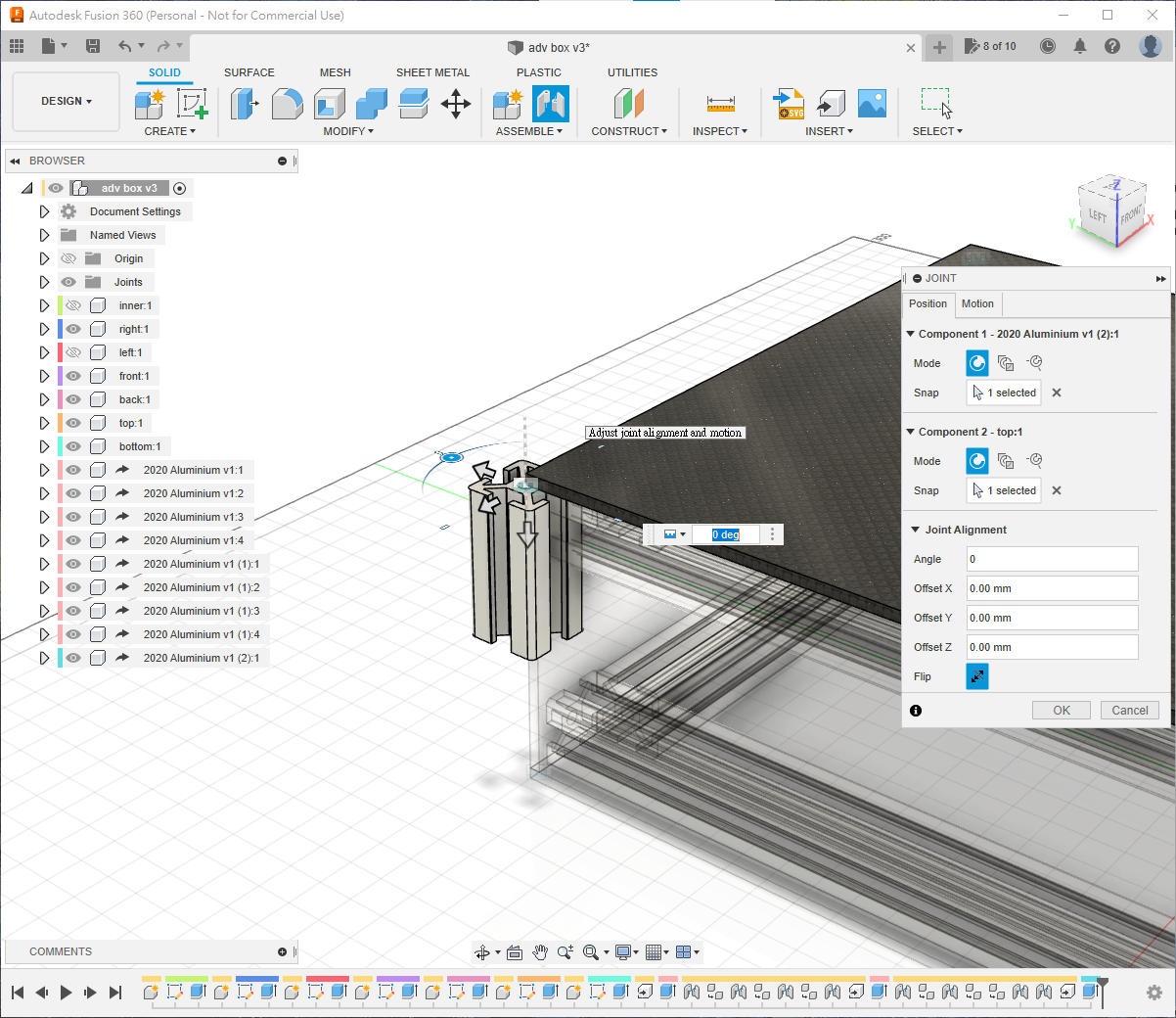
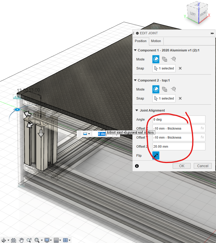
Copy and joint four vertical extrusions, show all components and run a final Interference check. The frame now contains all 12 members.
Final Assembly and Mounting Holes
Final Assembly
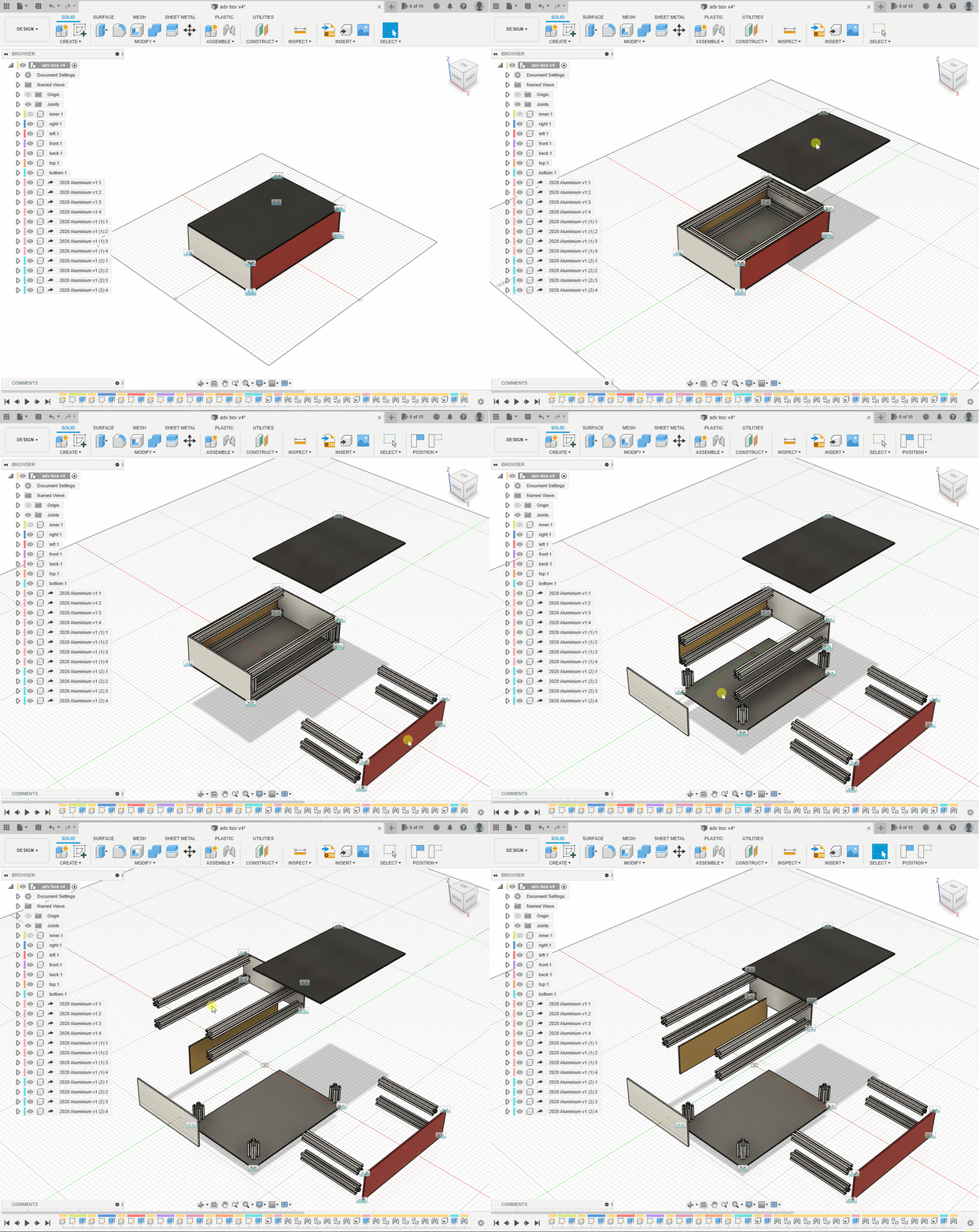
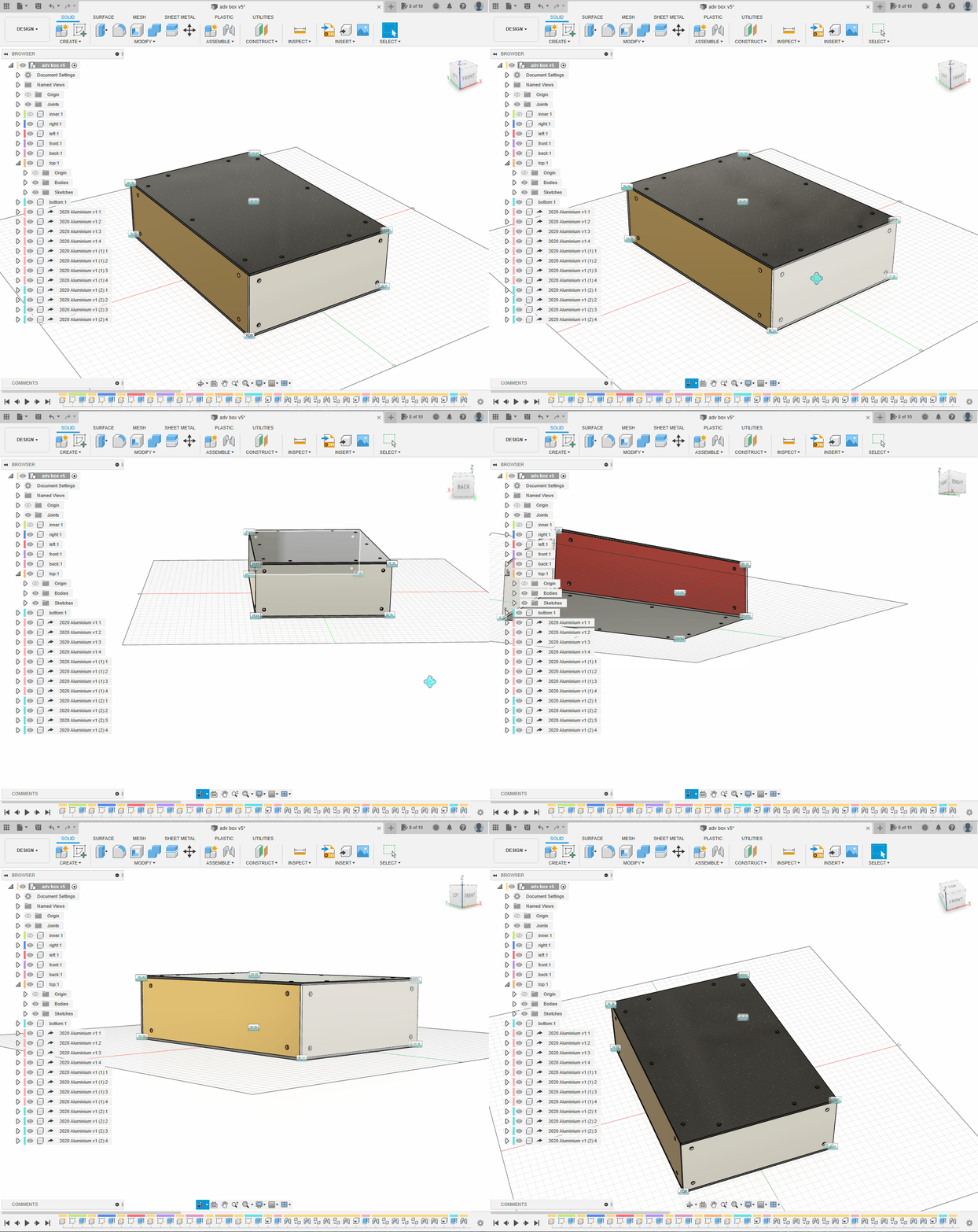
Drag the enclosure gently to identify panels that are not yet fully jointed.
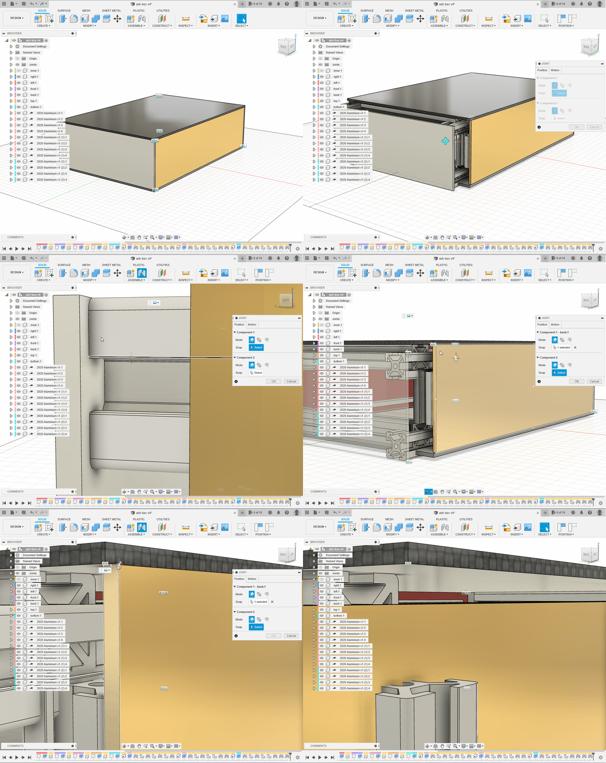
Press J and joint panel corners to one another, not to the aluminium members. If selecting the intended joint origin is difficult, hover over the required face and hold Ctrl to lock that face.
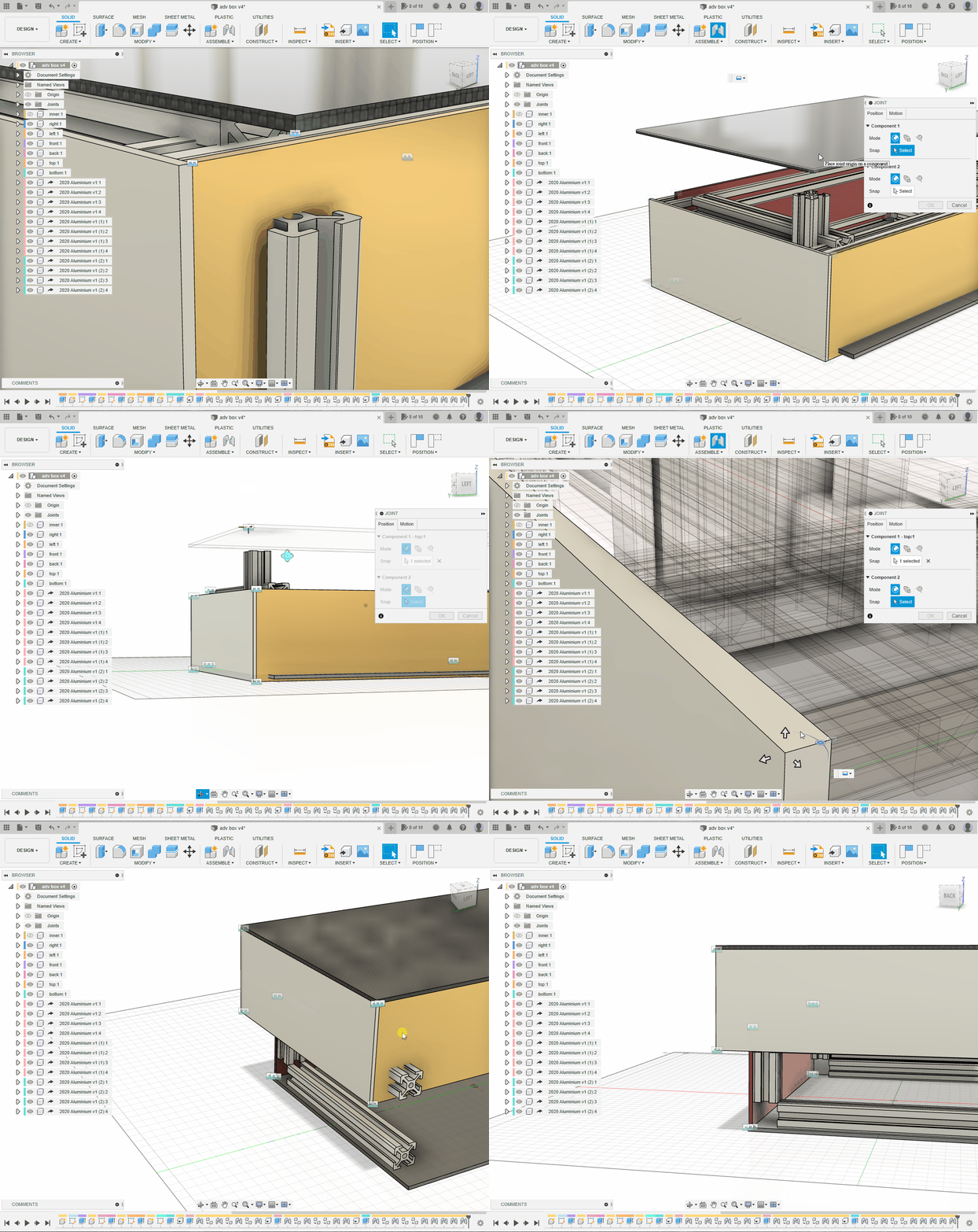
Drag the model again; every panel and extrusion should move as one assembly.
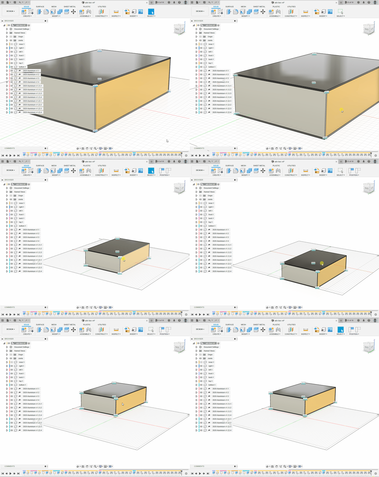
Mounting Holes
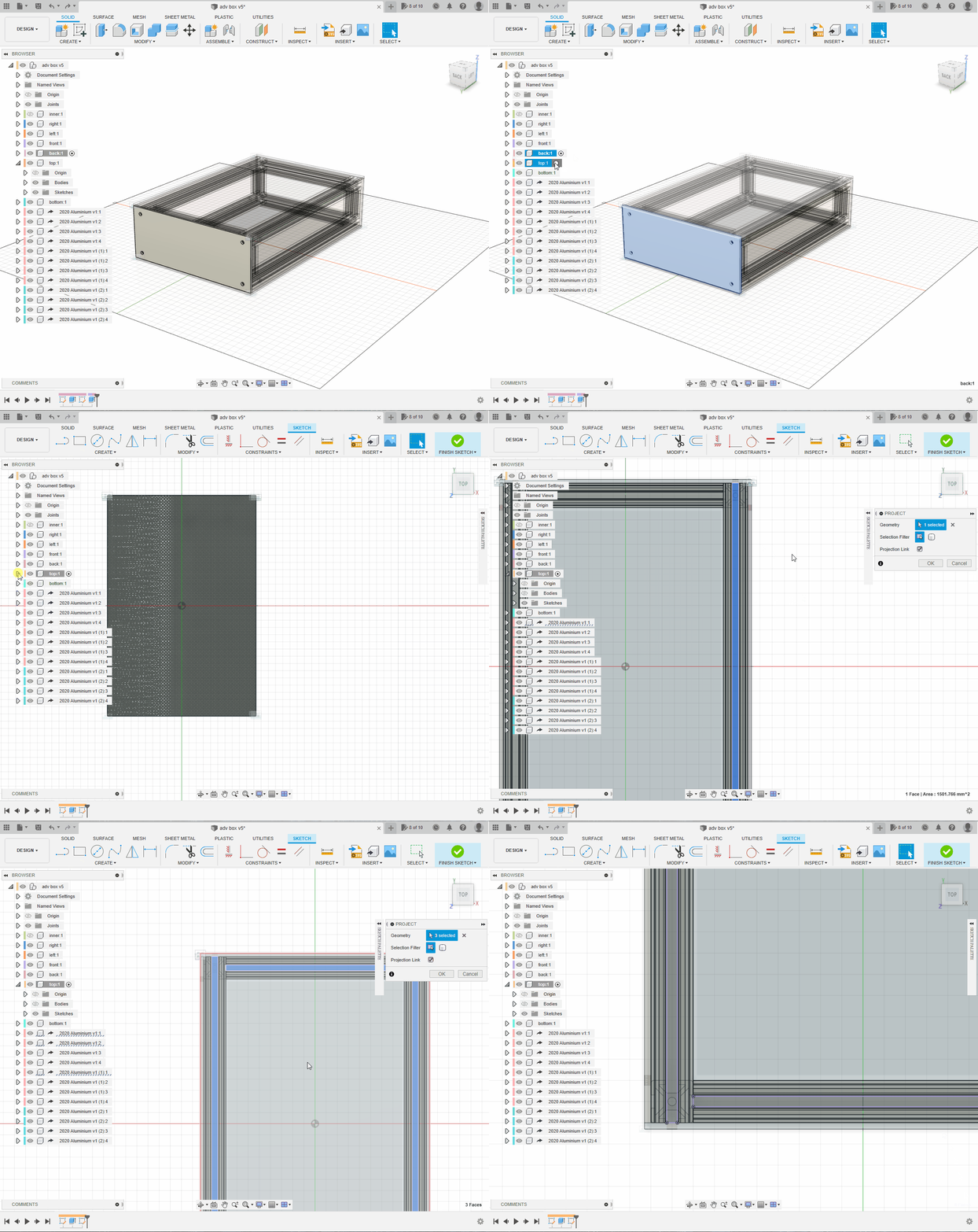
Activate right and create a sketch on its surface. Hide its body temporarily, press P to project the extrusion slots, then show the body again.
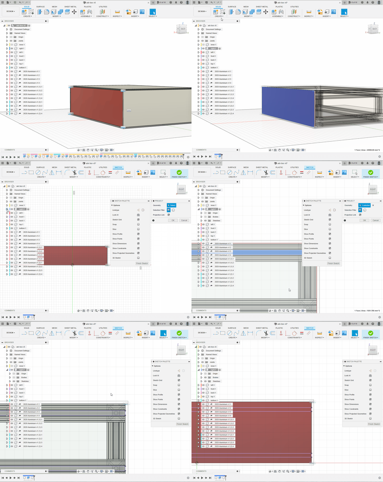
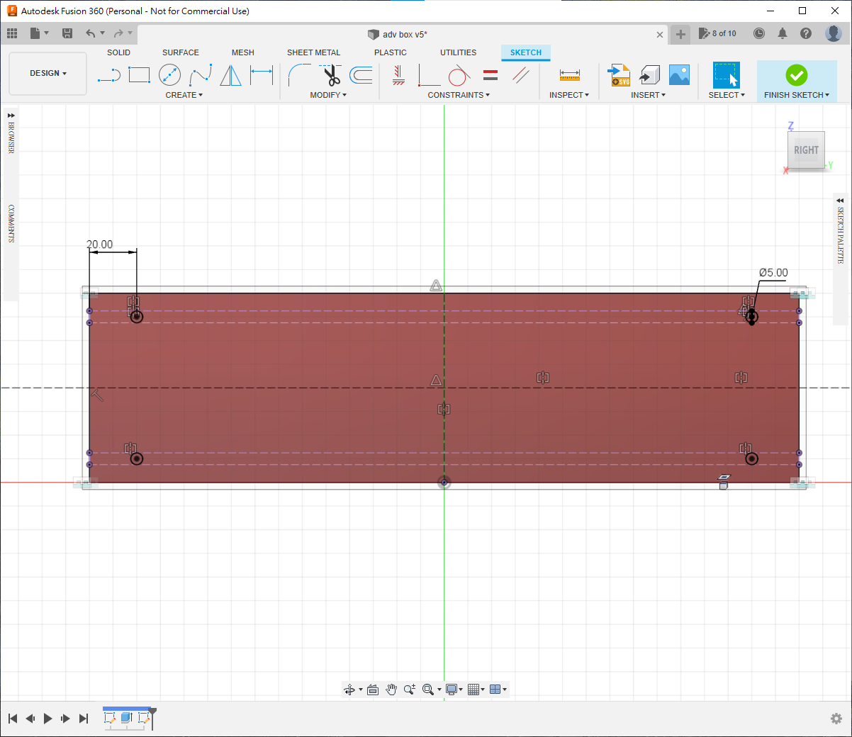
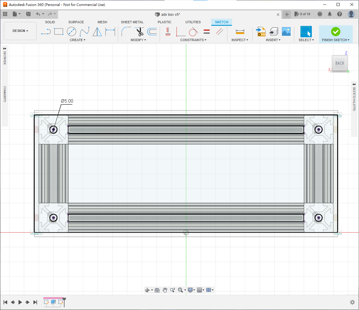
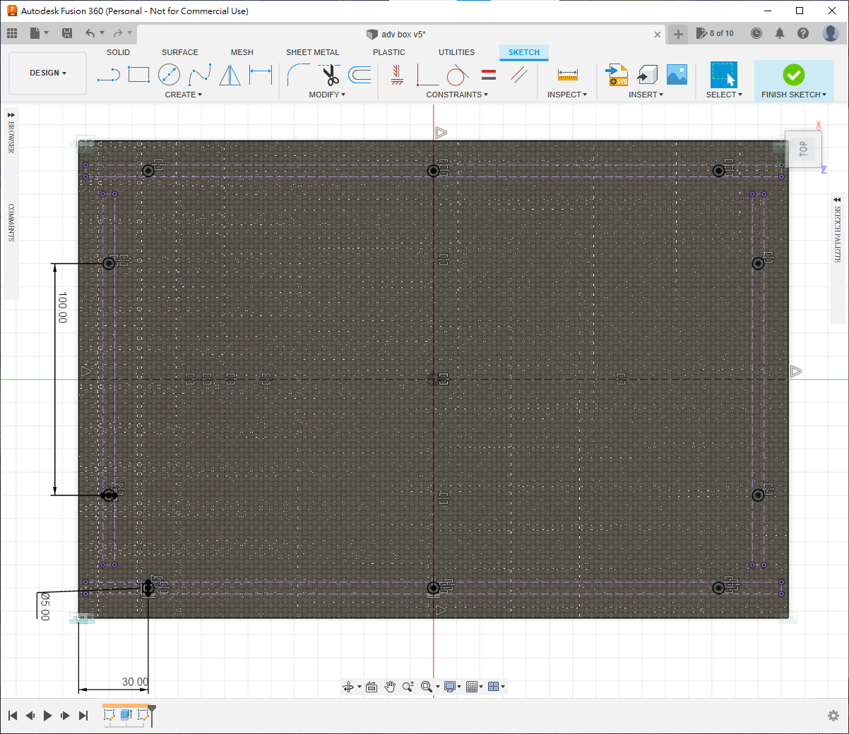
Draw four holes approximately as shown. Add a middle hole if the panel may bow without support.
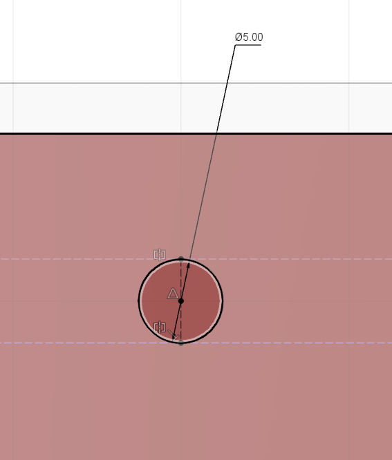
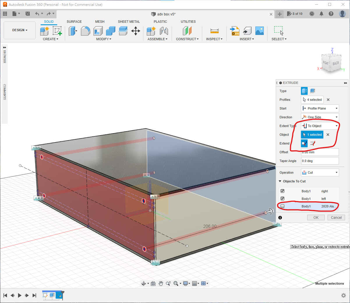
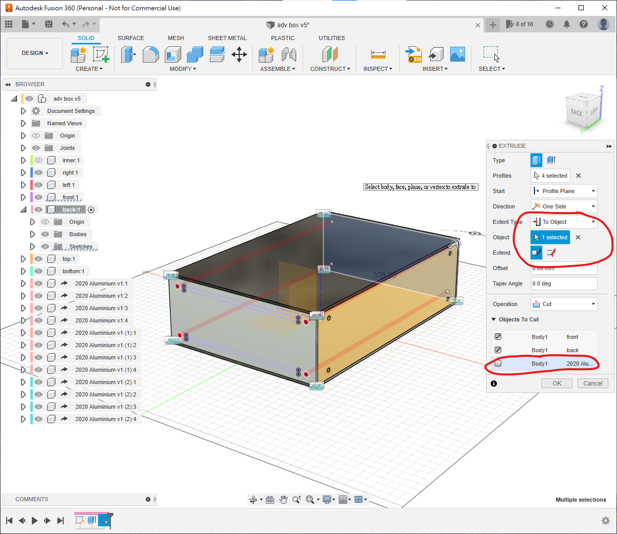
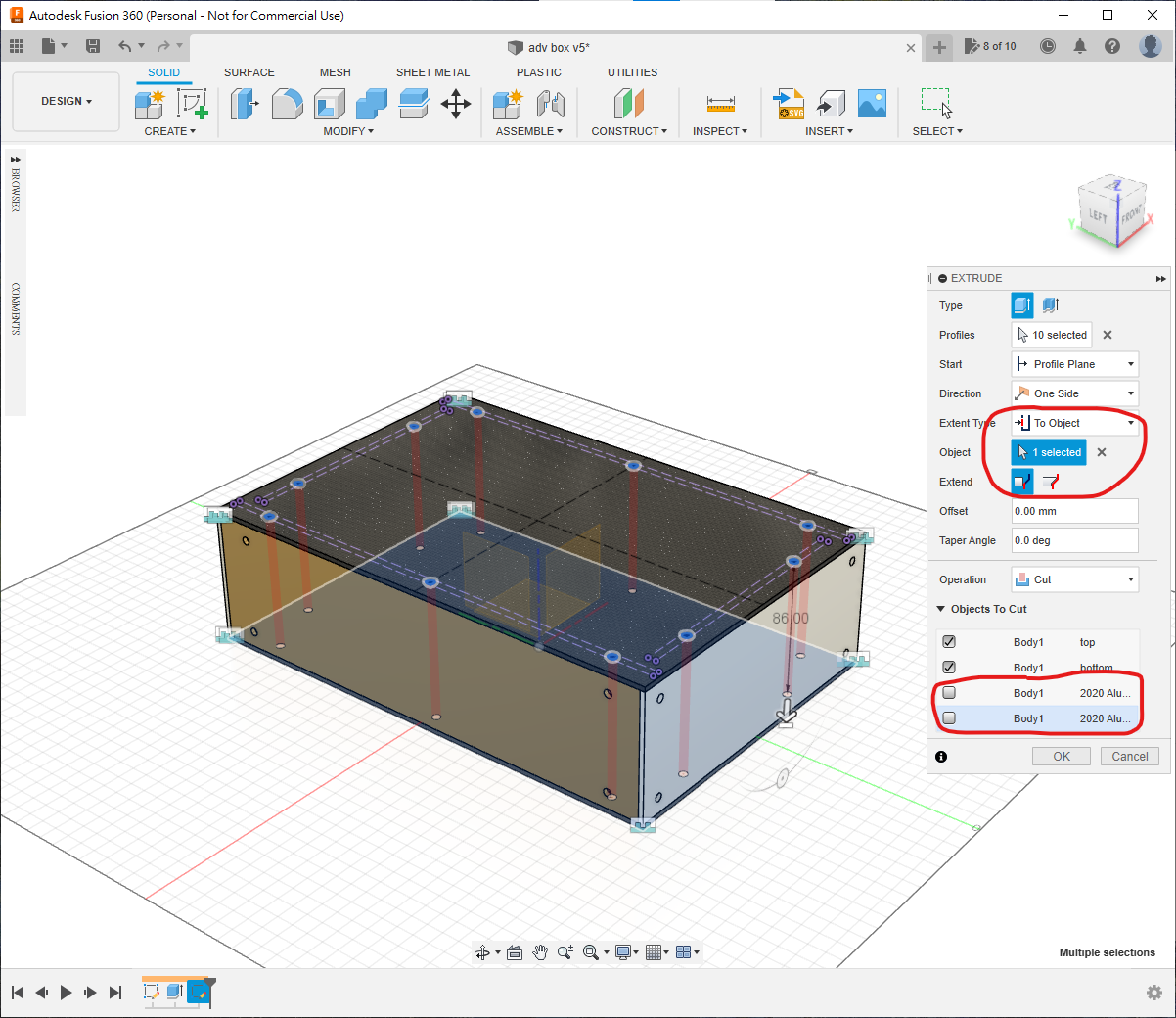
Press E, choose To Object, and cut through to the opposite panel. Under Objects to Cut, select only right and left so that the aluminium remains intact.
Activate back and repeat the projection workflow.
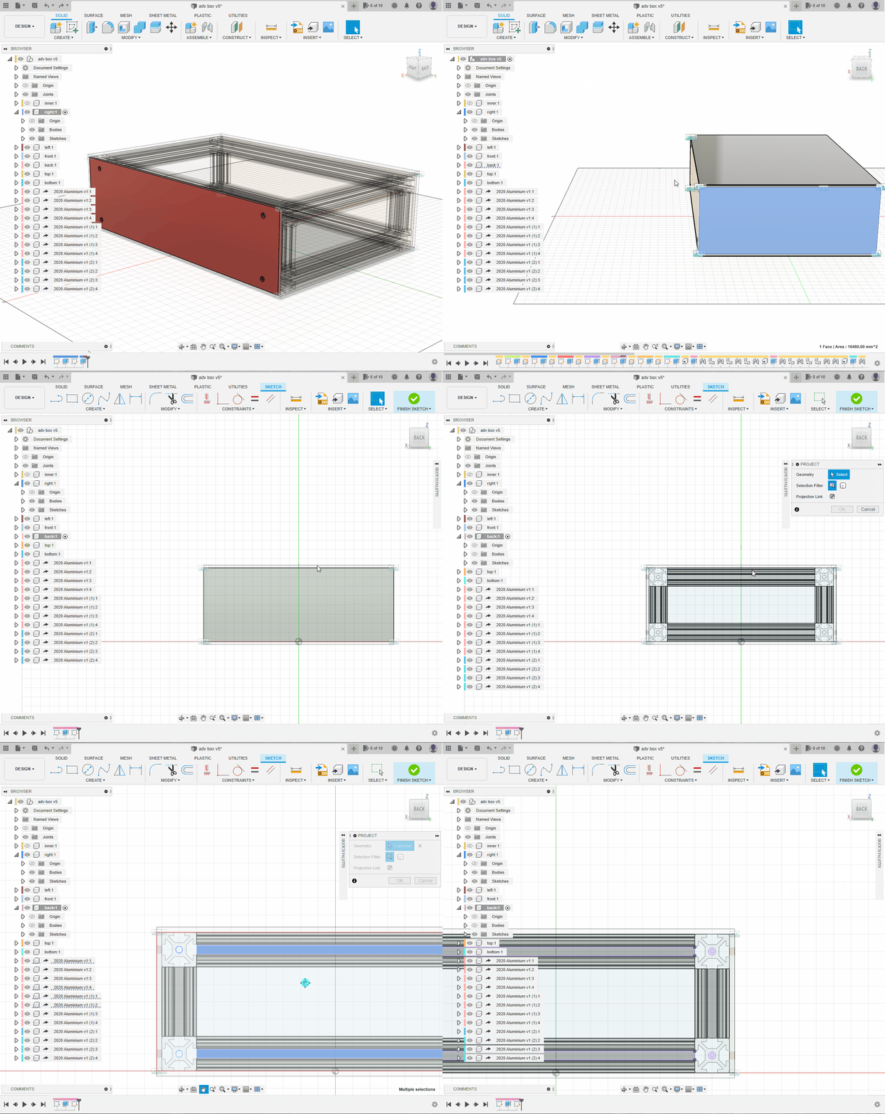
You can either place holes over the slots and use T-nuts, or screw into the extrusion end holes. End holes are not normally threaded, so confirm with the supplier whether they can tap them, whether the thread is M5 or M6, and how deep it will be.
Use To Object to cut both opposite panels, again excluding the extrusion from Objects to Cut.
Repeat for the remaining panel pairs.
Complete
Translation notice: This English page was generated automatically by AI and has not yet been reviewed by a human. It will be checked and revised page by page when time permits.