Advanced 3D Drawing
Fusion 360 contains many modelling tools beyond basic sketches and extrusions. This chapter introduces several of the most useful ones.
1. Planes and Axes
Construction planes are frequently used to place sketches away from existing faces.
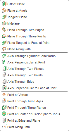
- Offset Plane: creates a plane parallel to a selected face at a specified distance.
- Midplane: creates a plane halfway between two faces, particularly useful for mirroring.
- Plane Through Two Edges / Plane Through Three Points: defines a plane from existing geometry, often for splitting a solid.
Exercise 1
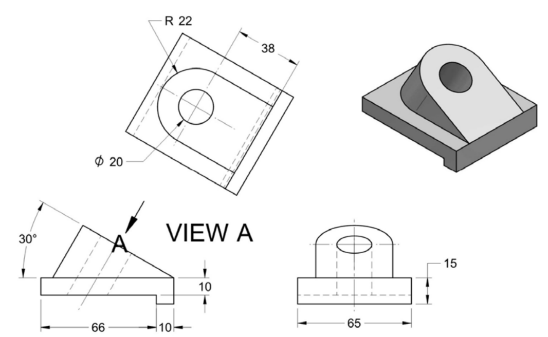
- Sketch the base in Front view.
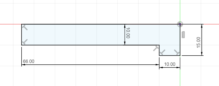
- Extrude it symmetrically by
65 mm.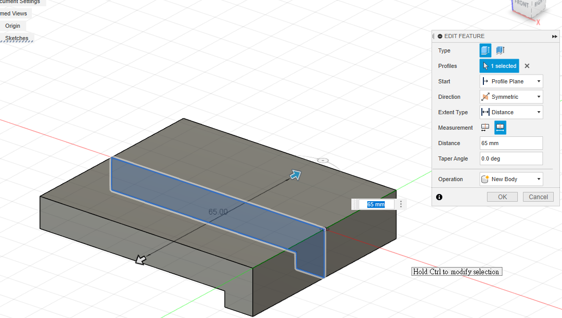
- Use
Plane at Angleto create a plane at 30°.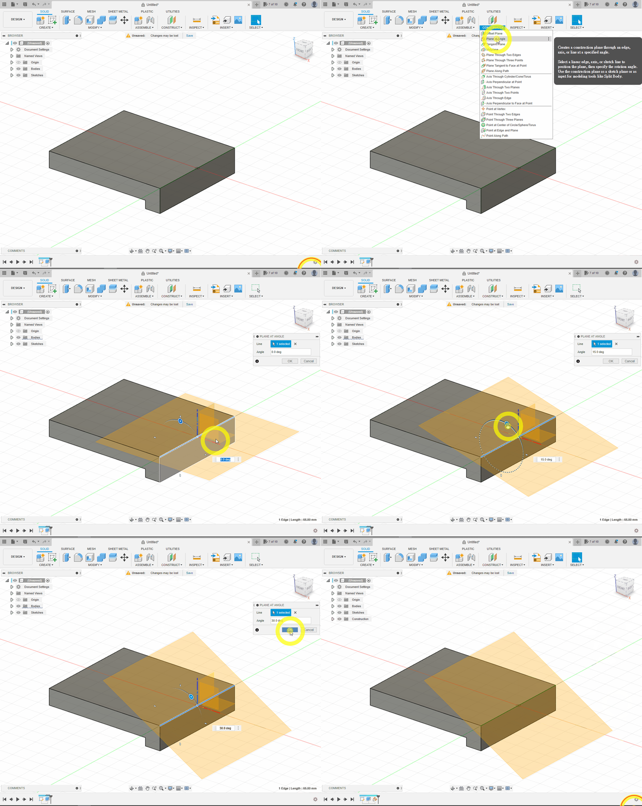
- Sketch on the angled plane and extrude the feature.
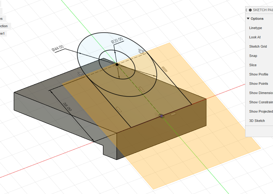
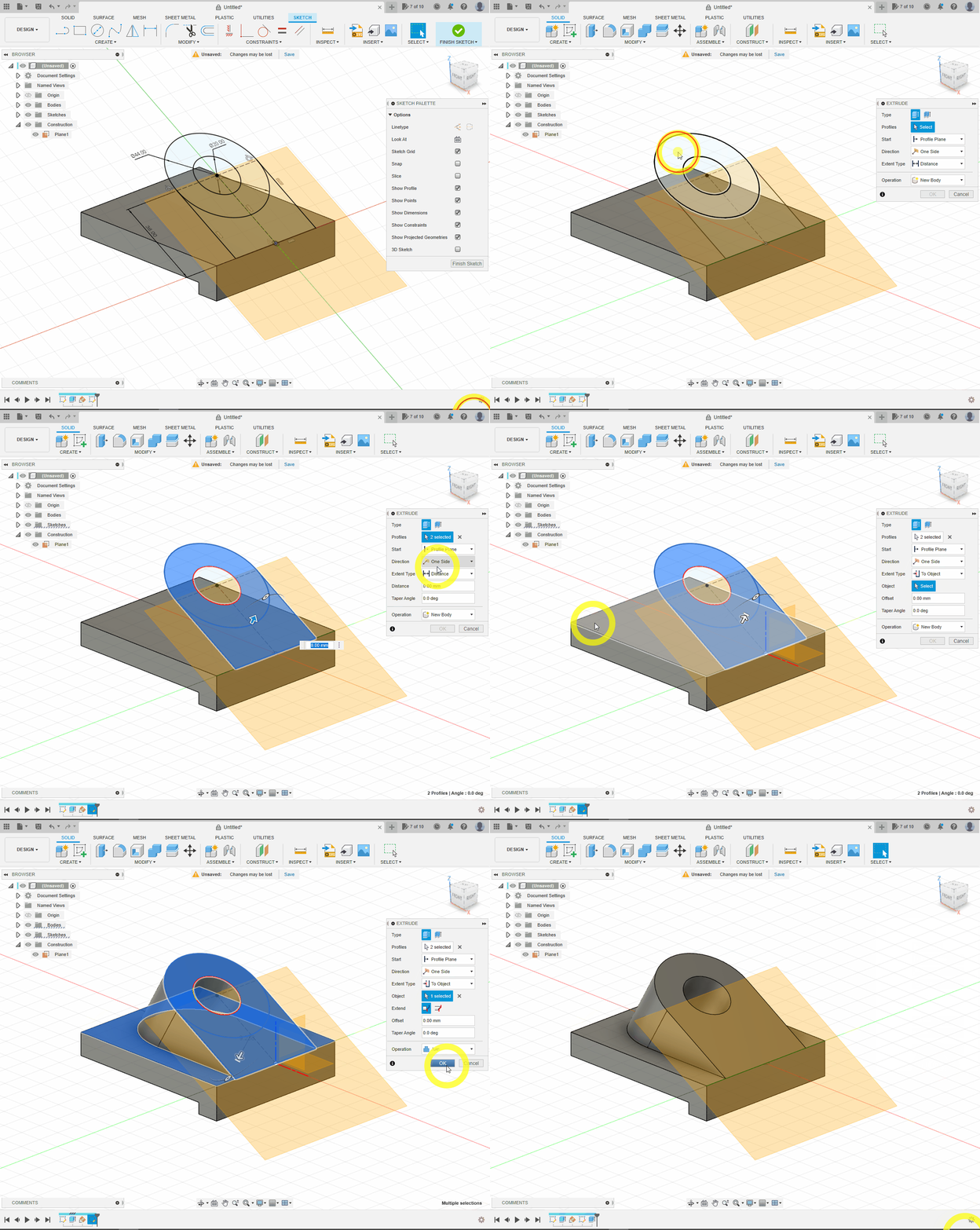
- Show
Sketch2again and cut the hole down to the bottom as specified.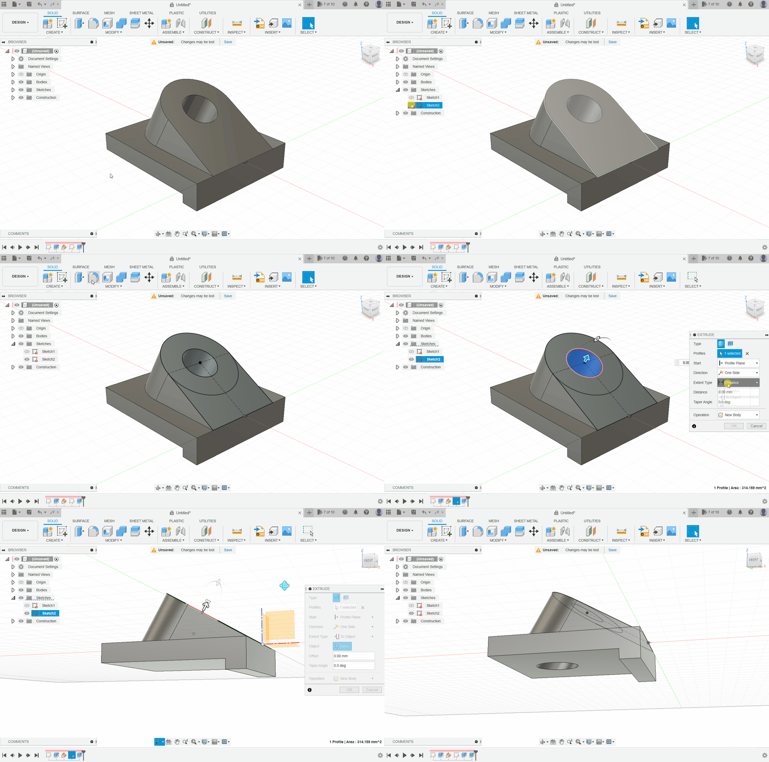
Exercise 2
Each grid square represents 10 × 10 mm.
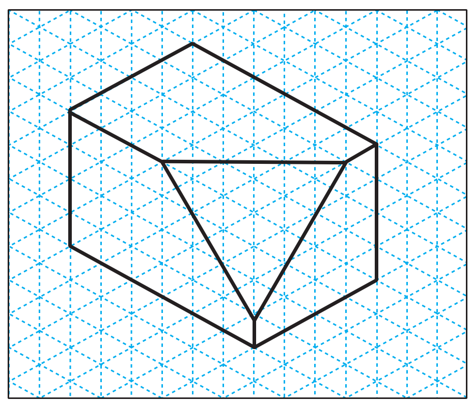
- On the front plane, sketch the rectangle and define the first sloping face.
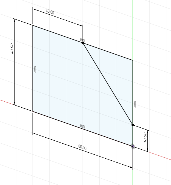
- Extrude the full profile by
40 mm.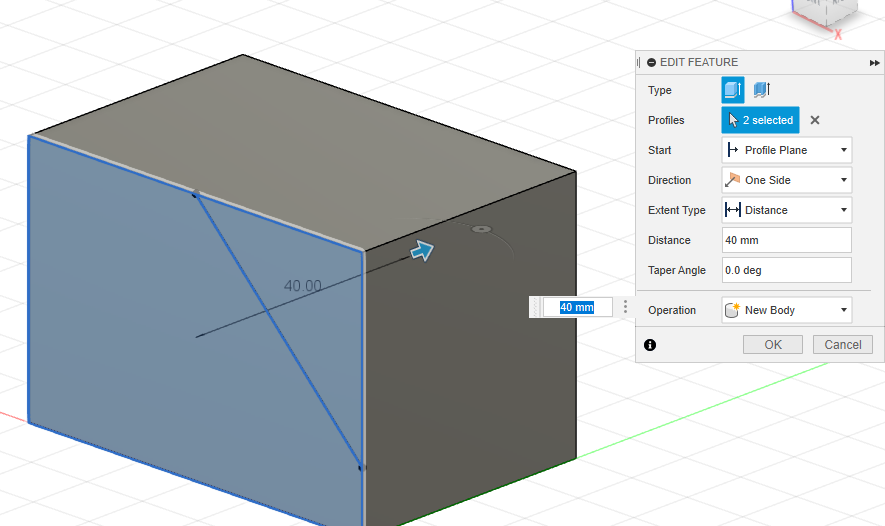
- Sketch the second slope on the side face.
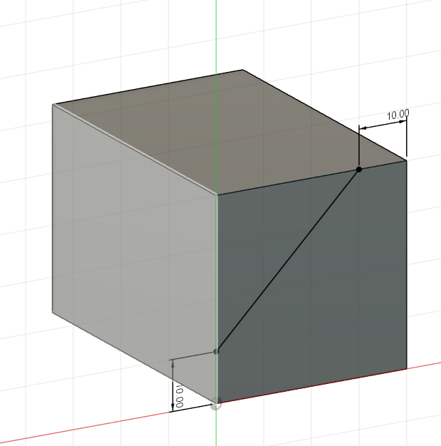
- Show both sketches and create
Plane Through Three Points.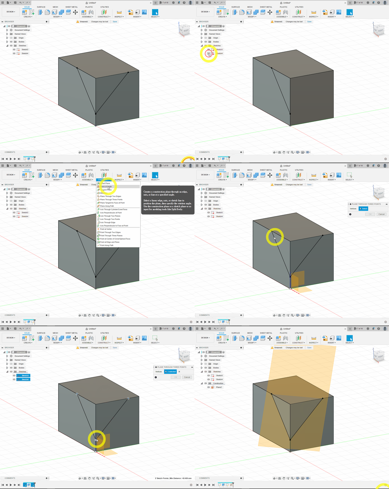
- Use
Split Body, then hide the plane and unwanted corner.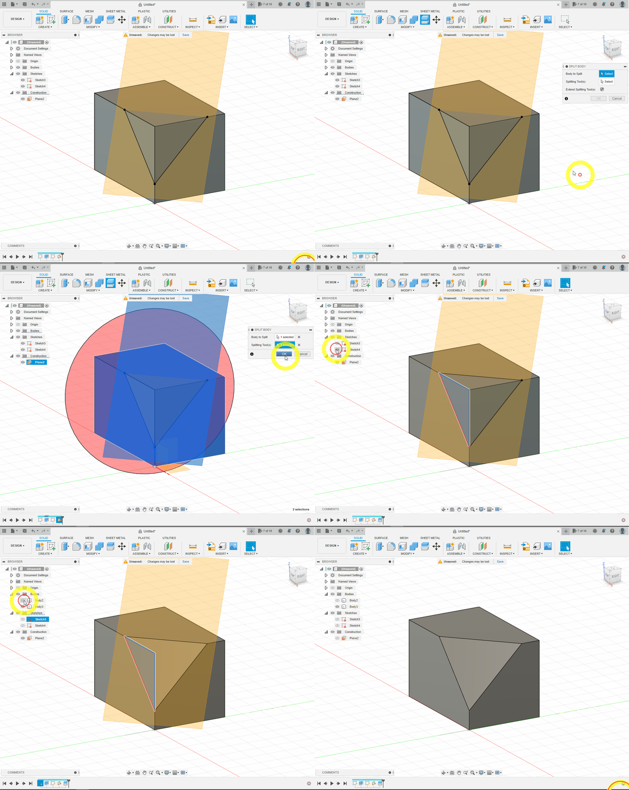
2. Mirror and Pattern
Mirror and Pattern reproduce repeated features accurately and efficiently.
Exercise 1
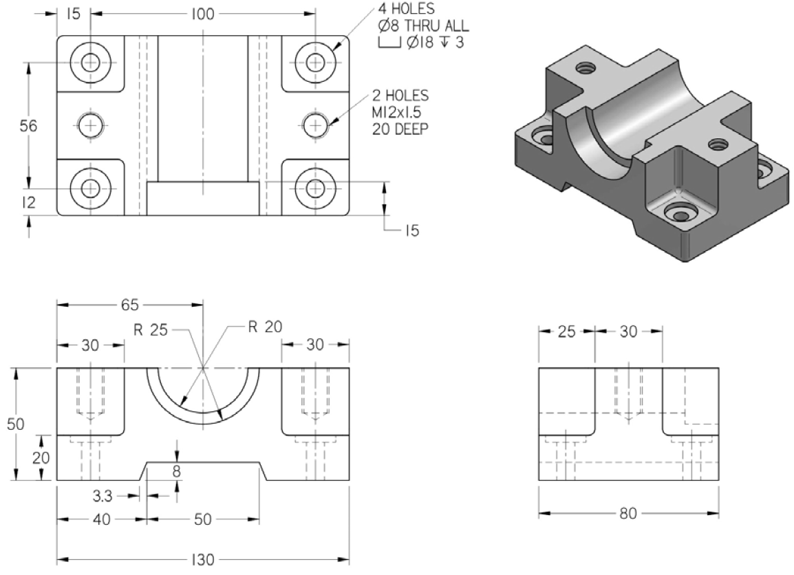
Sketch a
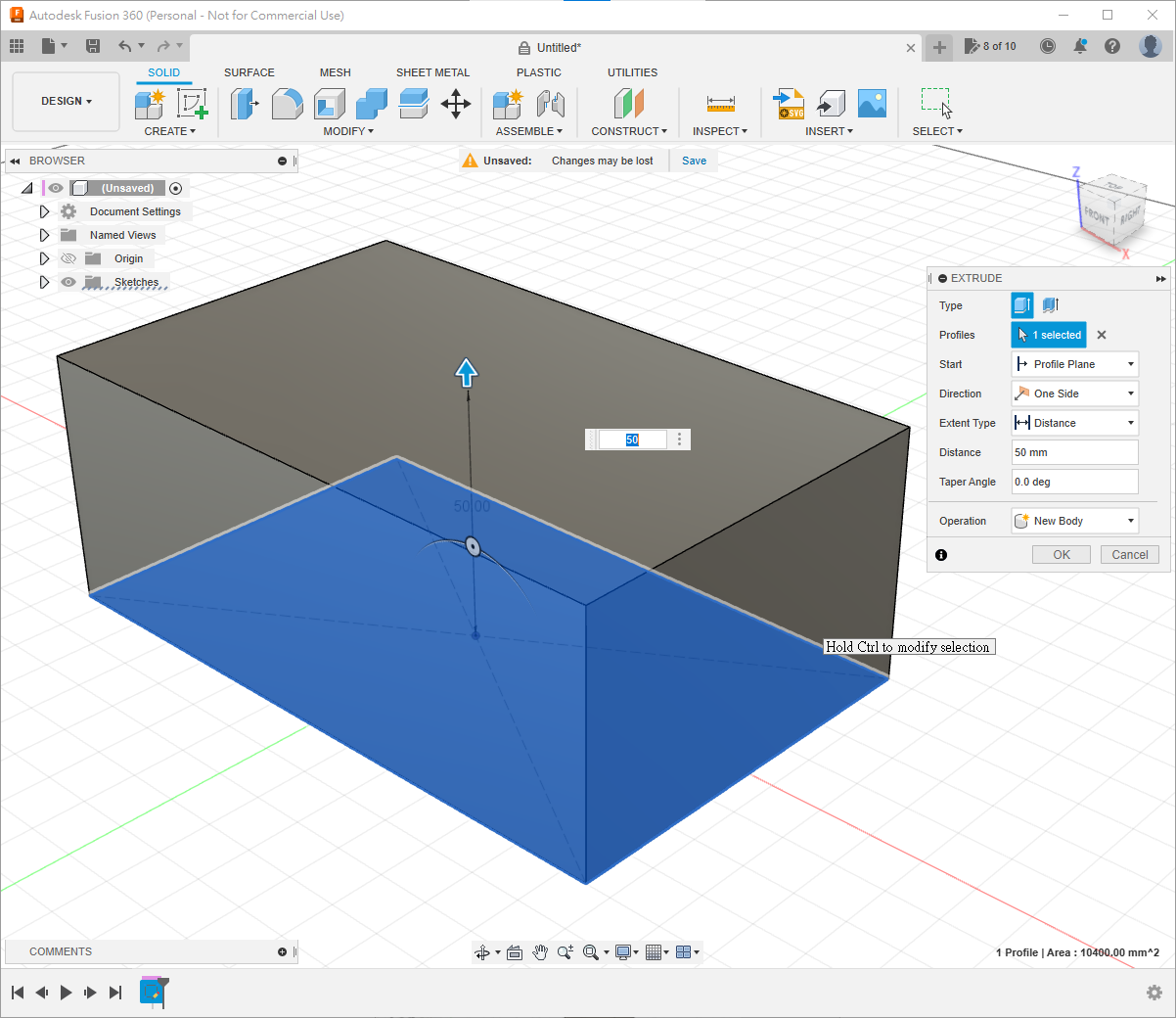
130 × 80 mmcentre rectangle on XY and extrude it50 mm.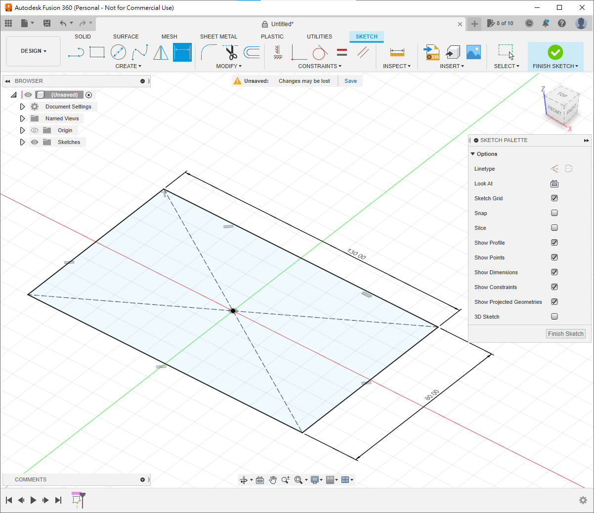
On top, sketch a
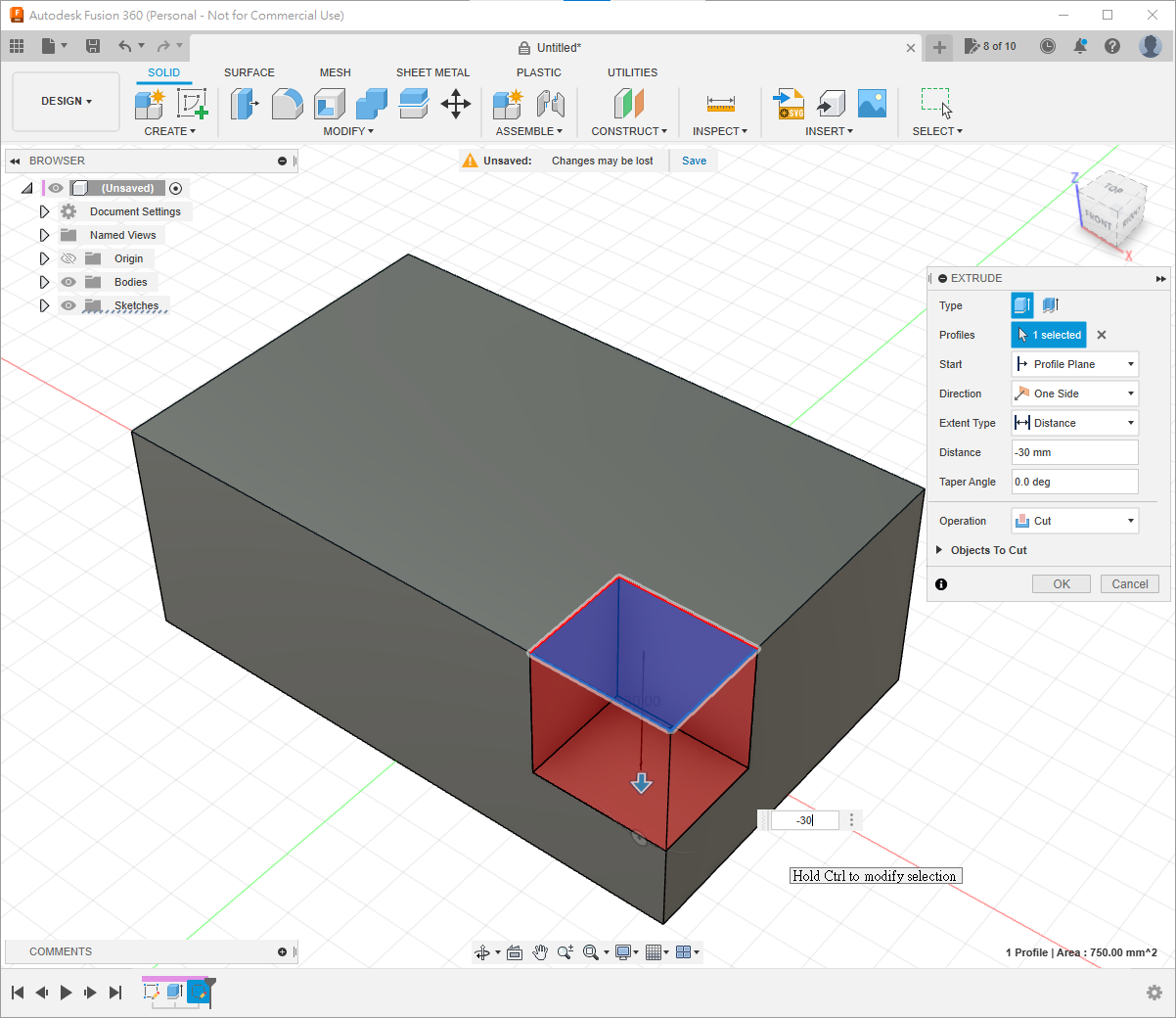
30 × 25 mmrectangle and cut it30 mmdeep.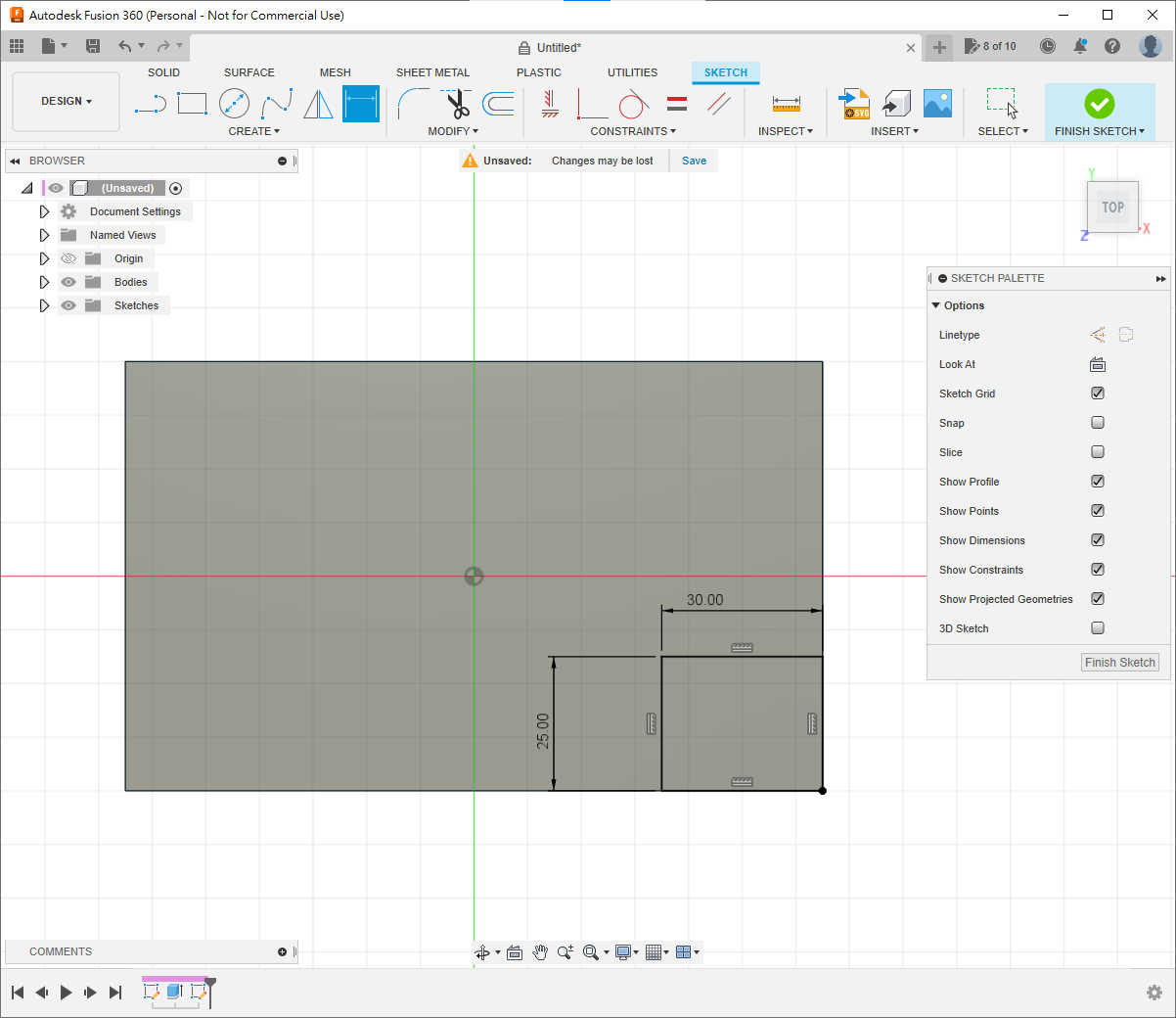
Run
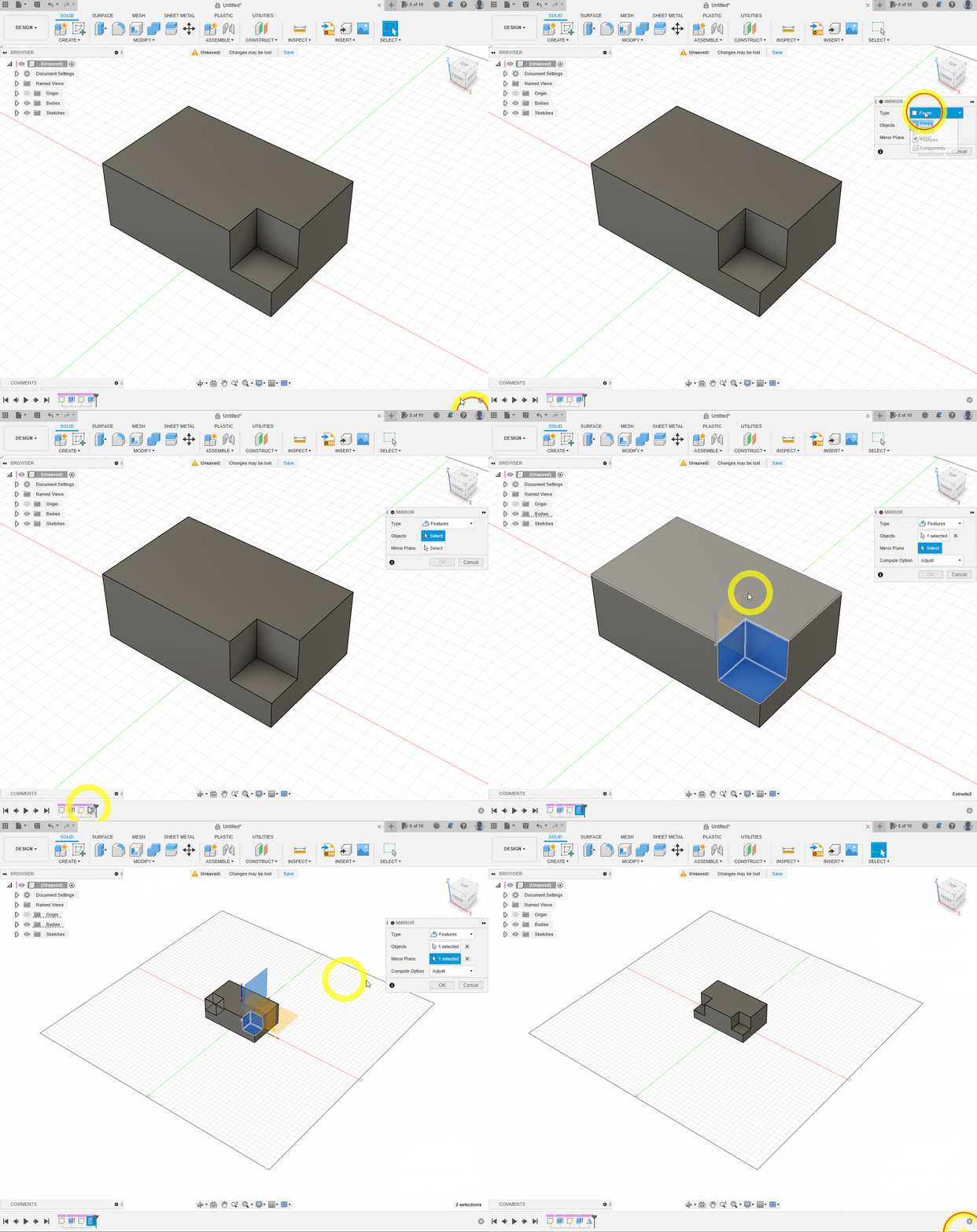
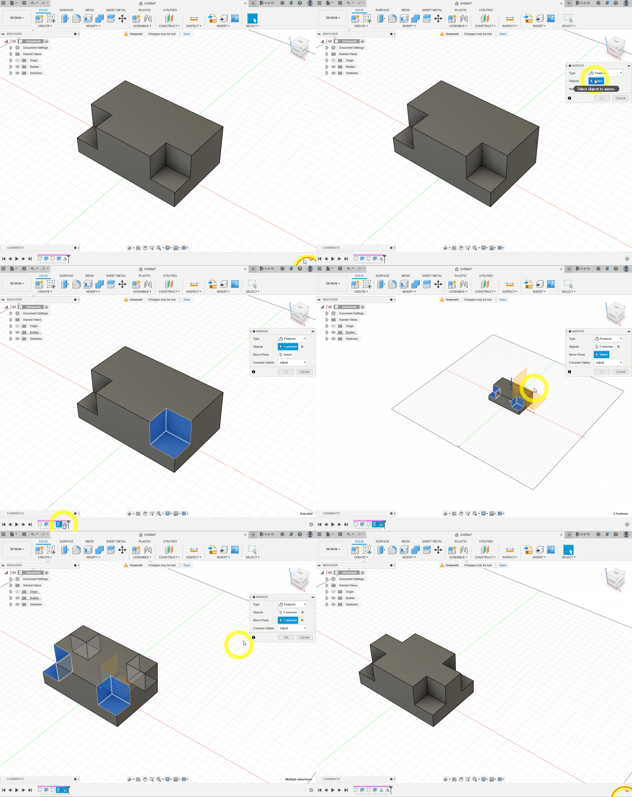
Mirror, chooseFeature, select the cut and use the YZ plane.Mirror again, selecting both the original cut and first Mirror feature, across XZ.
- Press
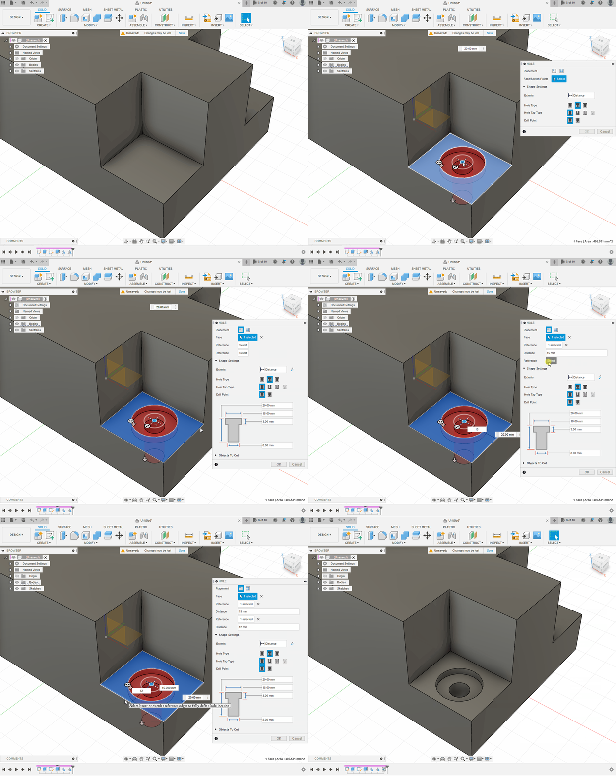
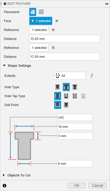
H, place a hole 15 and 12 mm from the two edges, set Extent toAll, Hole Type toCounterbore, Tap Type toSimple, and use any drill point because it is through-all. 4 HOLES Ø8 THRU ALL ⌴Ø18 ↧3means four 8 mm through-holes with an 18 mm counterbore 3 mm deep.
- Use
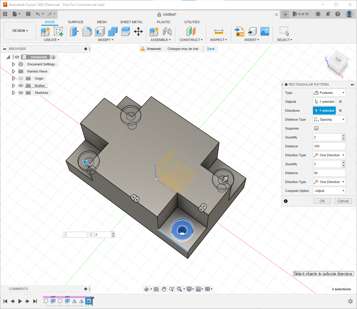
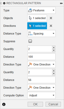
Rectangular Patternwith typeFeature, select the Hole feature, choose the two directions and set spacing to100 mmand56 mm.
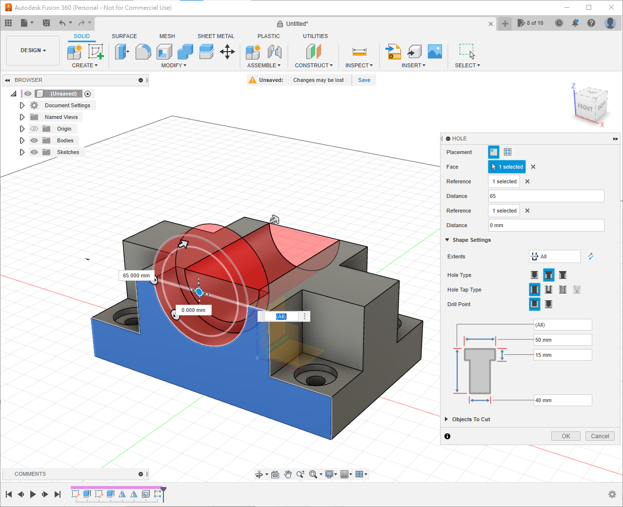
- Create the central circular opening either by sketching the semicircles and cutting them, or with Hole.
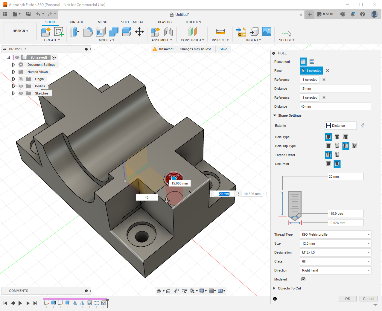
- Create the final threaded hole 15 and 40 mm from the edges. Choose Simple hole, Tapped, the pointed drill tip, M12 × 1.5 and
Modeledthreads.
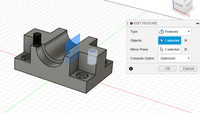
- Mirror the threaded hole across YZ; use
Optimizedas the Compute Option so the complete threaded feature is mirrored.
- Sketch on the front and remove the specified region with Extrude.
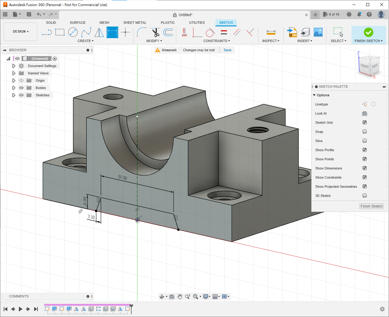
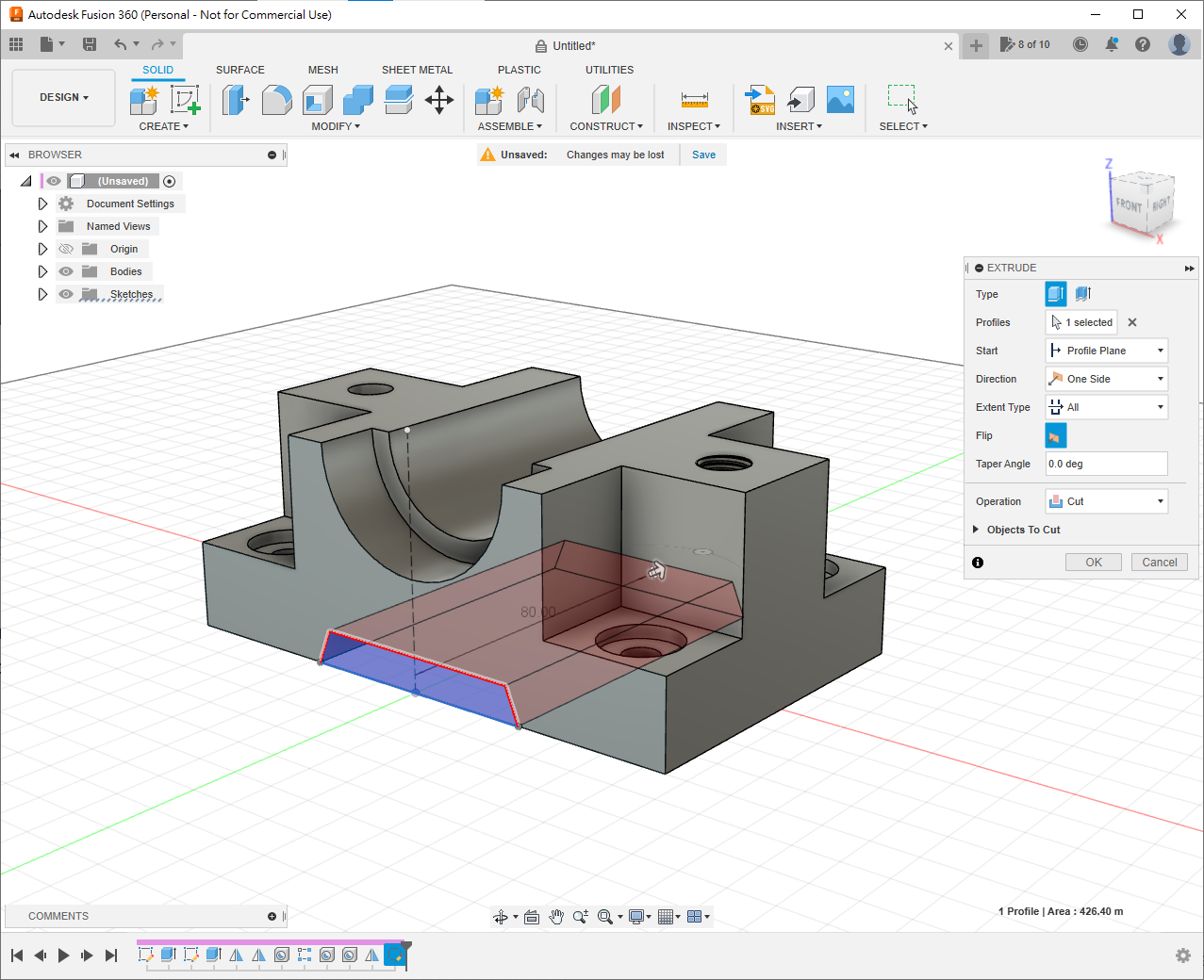
- Apply
2 mmfillets to the specified edges.
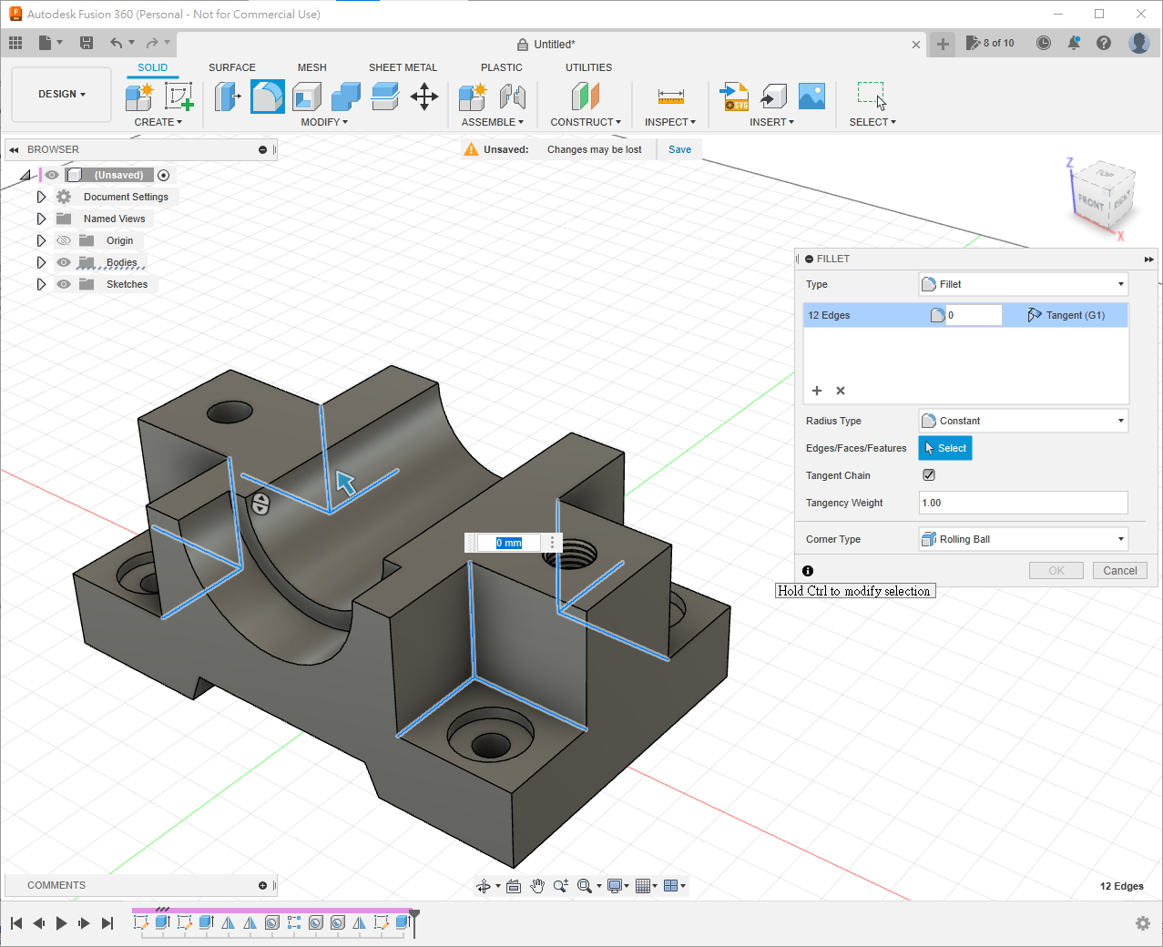
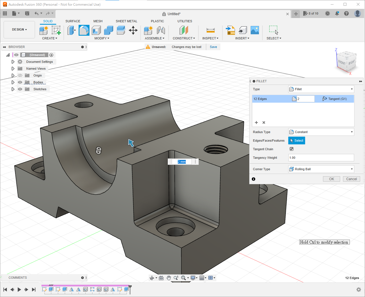
3. Shell
Shell removes selected opening faces and gives the remaining solid a specified wall thickness, avoiding a separate offset body and Boolean subtraction.
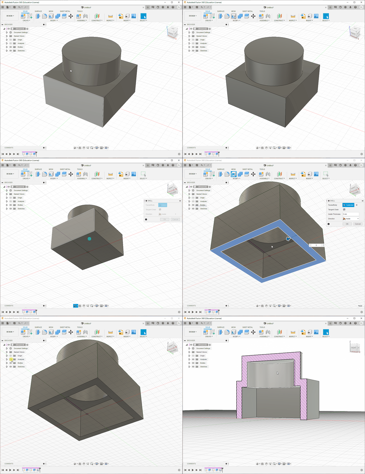
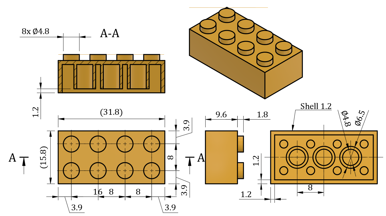
Exercise 1
Hints
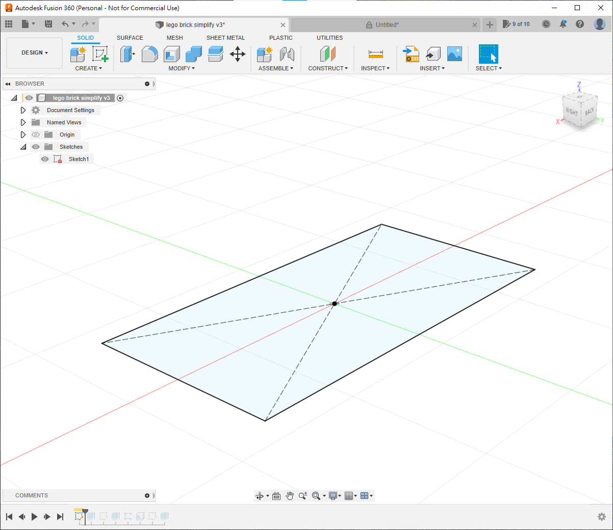
Create and extrude the base.
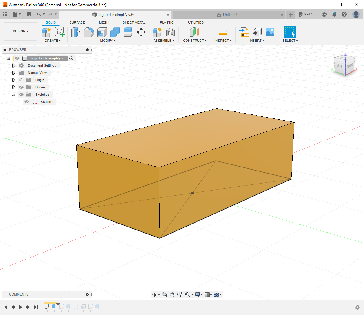
Create one cylinder and use Rectangular Pattern to make eight.
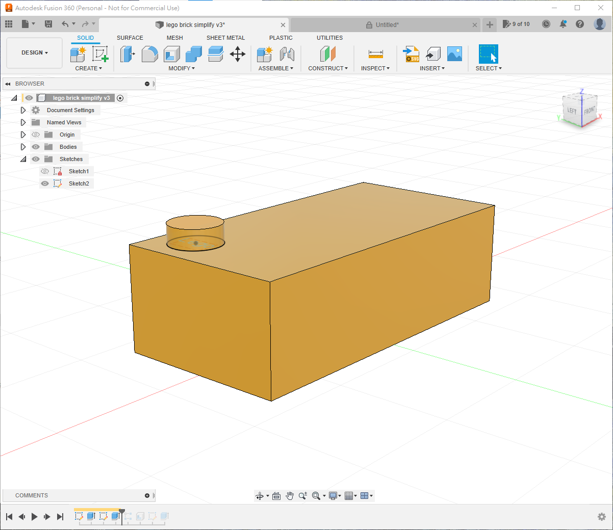
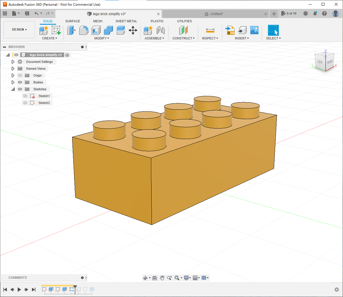
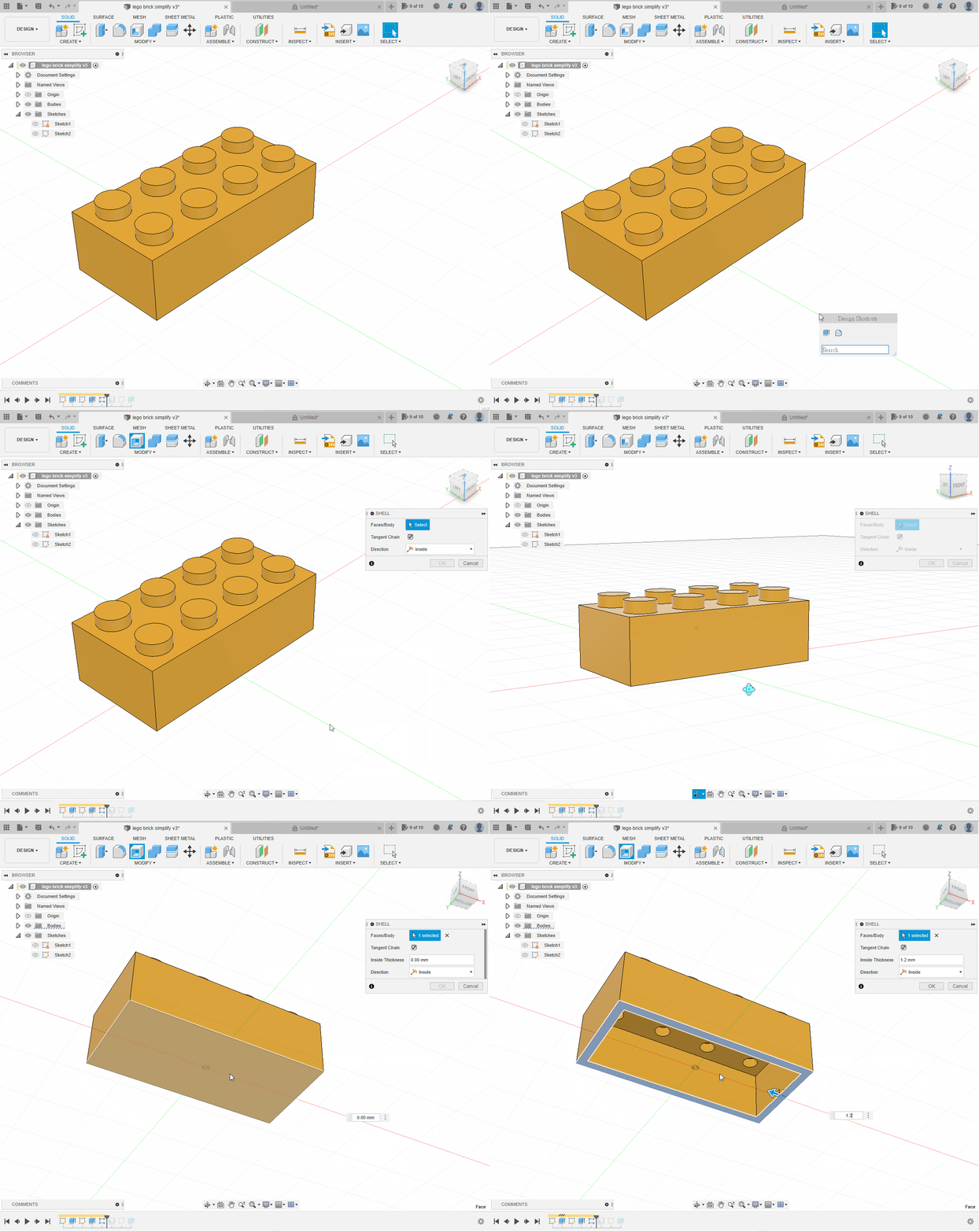
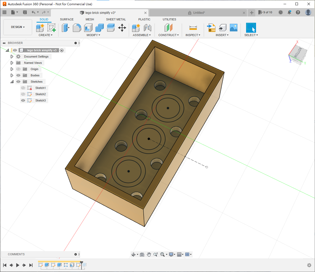
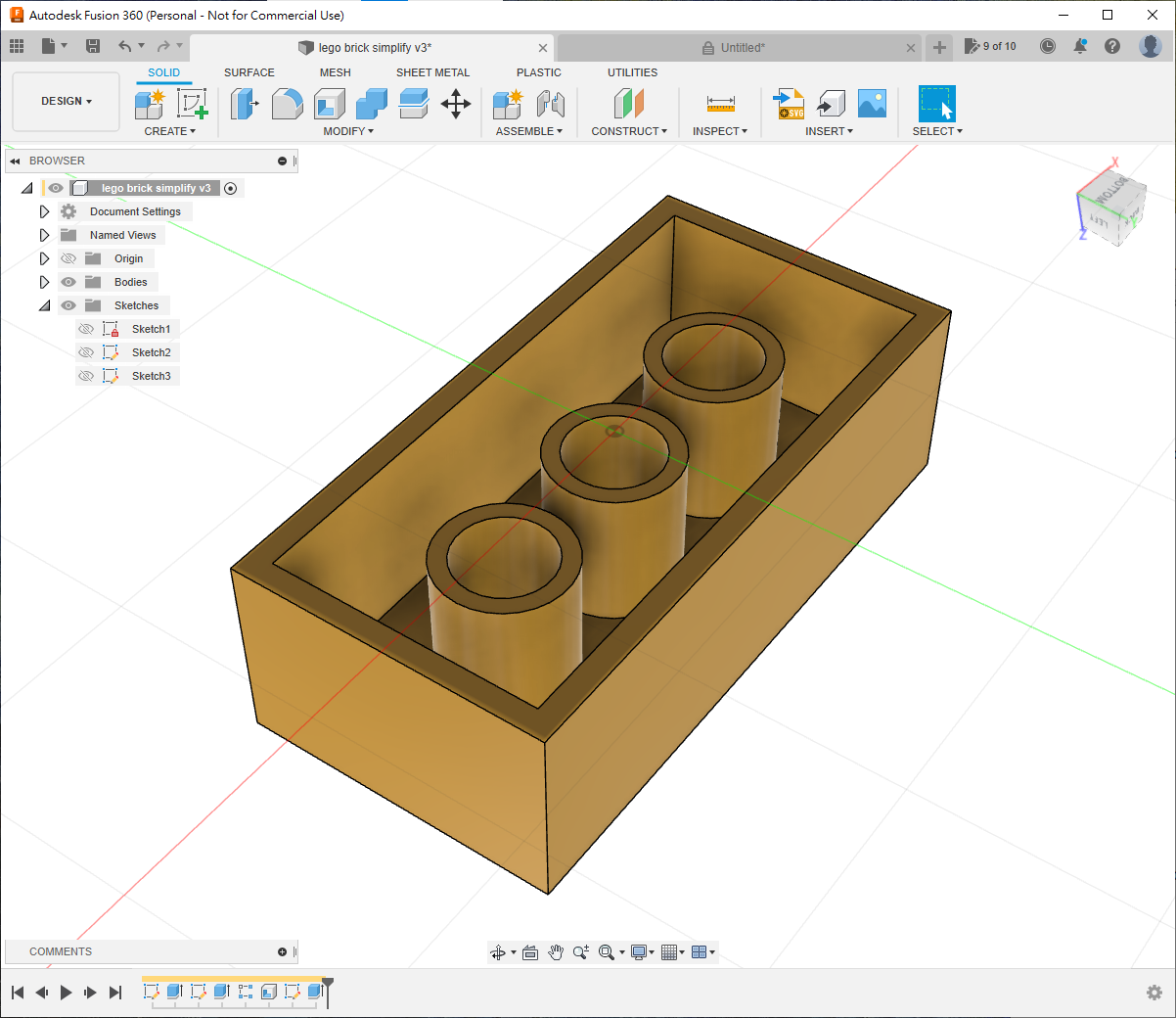
Sketch the three lower cylinders from underneath. They stop 1.2 mm above the very bottom of the LEGO-style part.
4. Loft
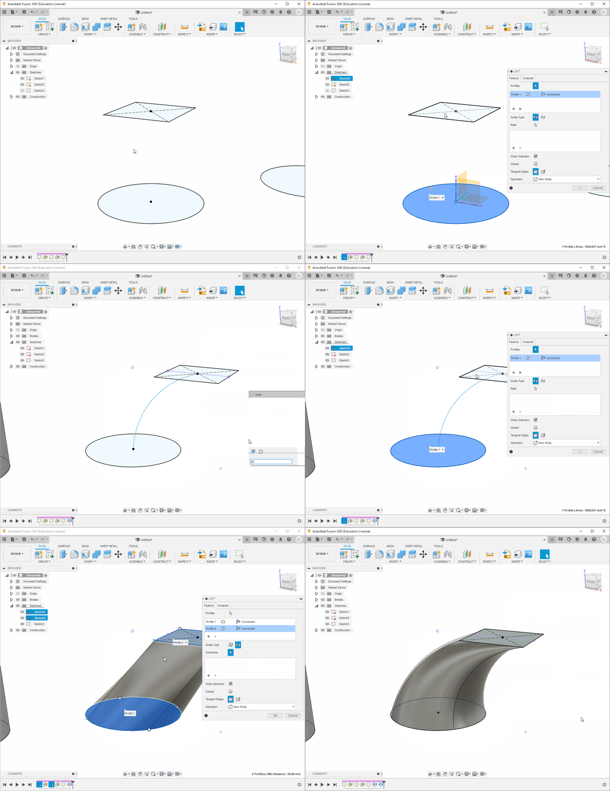
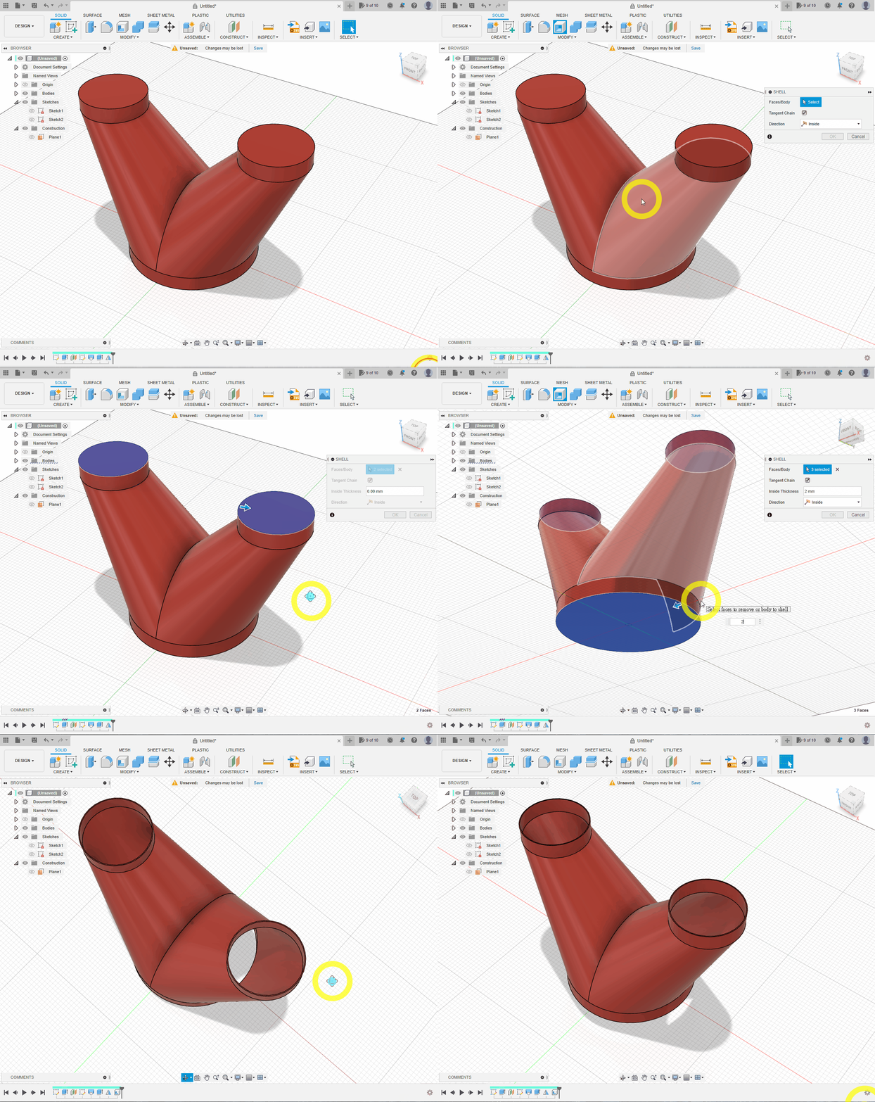
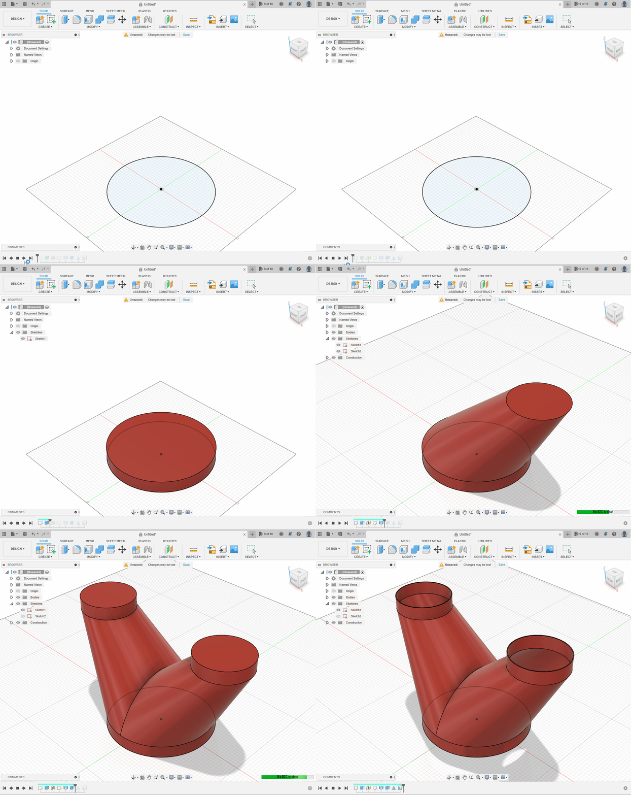
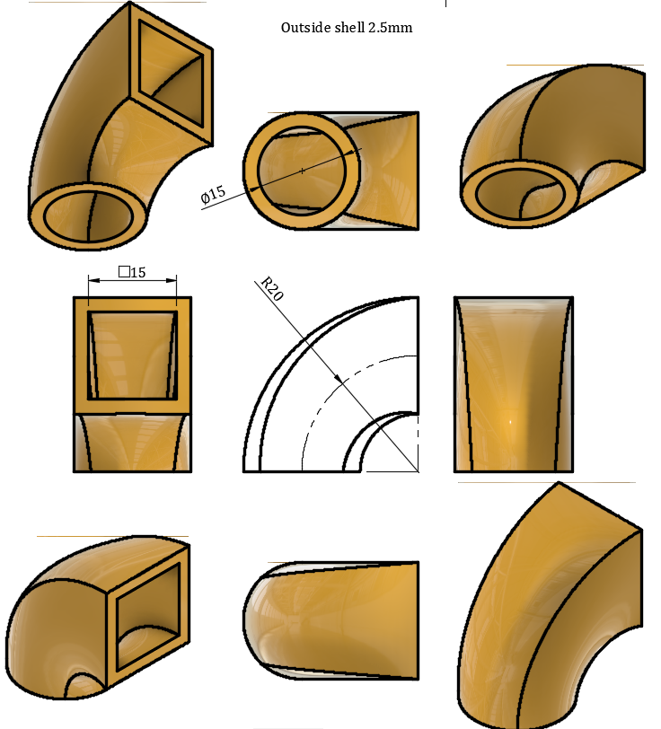
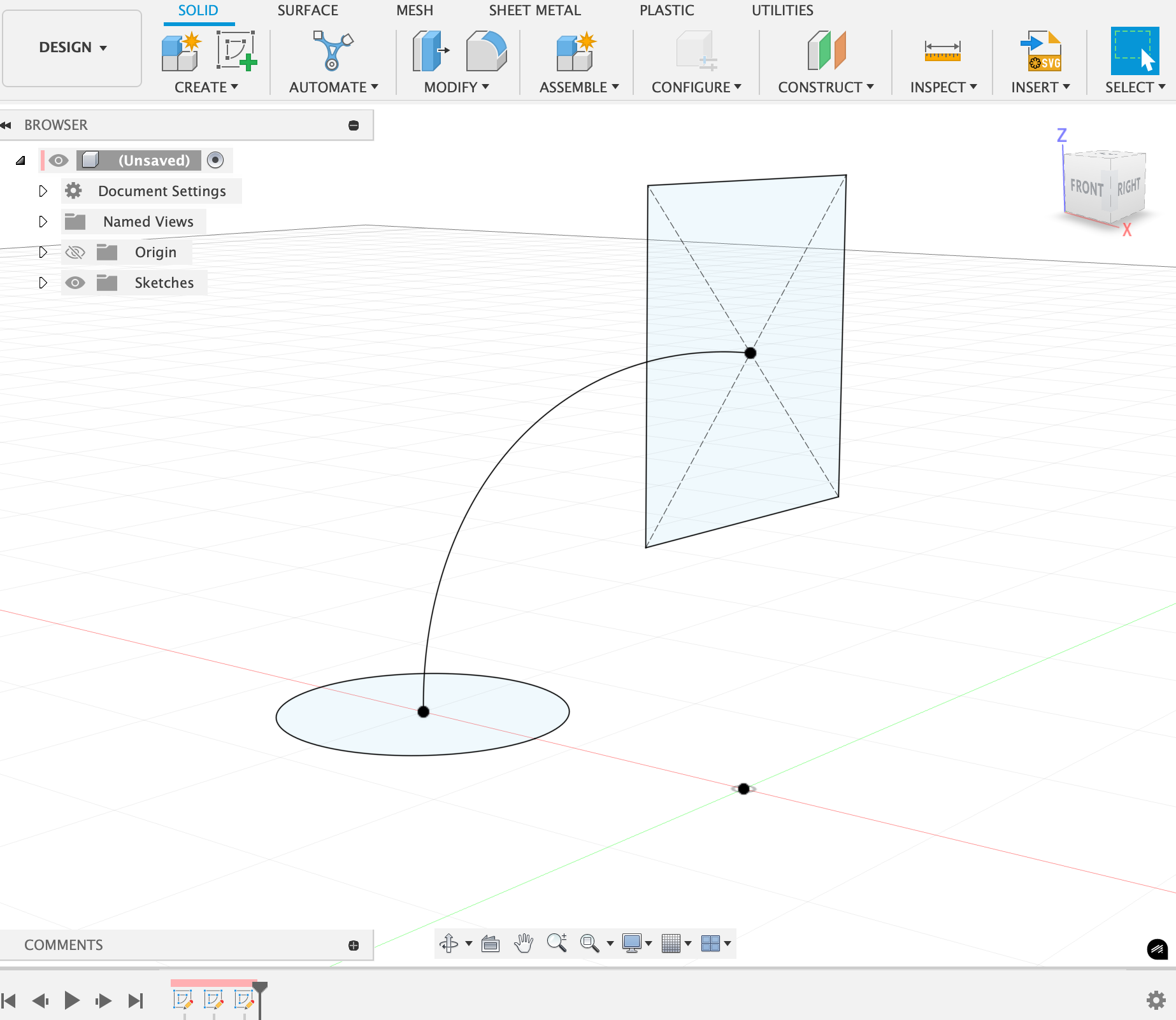
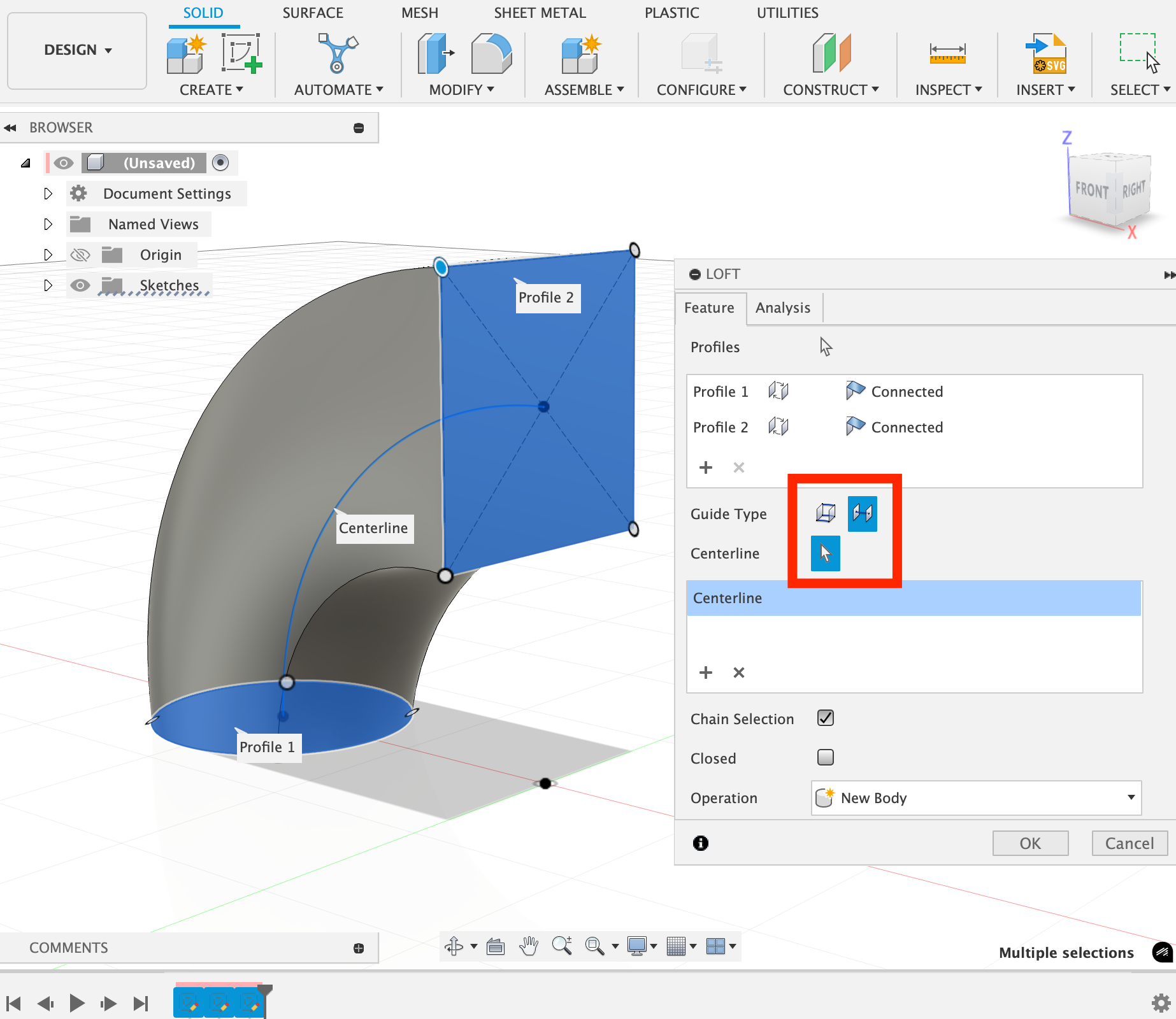
Loft joins profiles of different shapes and sizes. It is useful for transitions such as round-to-square ducts. Profiles can be connected directly or guided by rails/centre lines.
Exercise 1
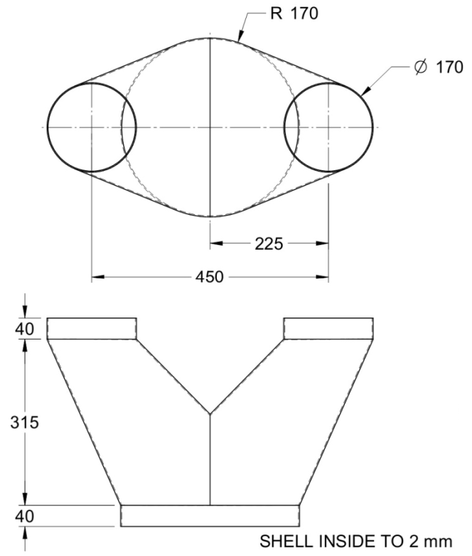
- On XY, draw a circle of radius
170 mmand extrude it40 mm.
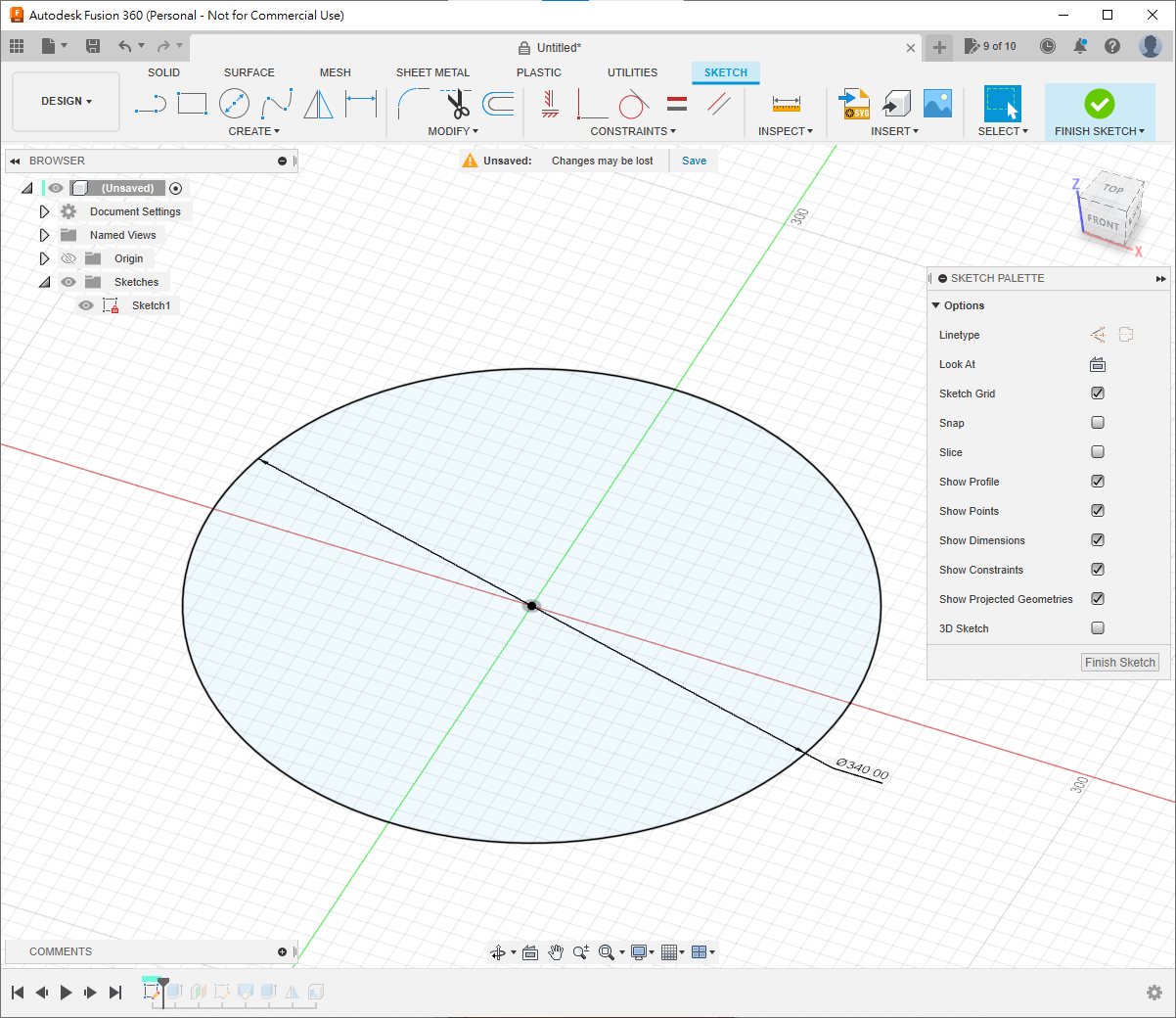
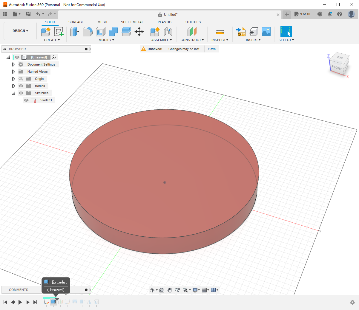
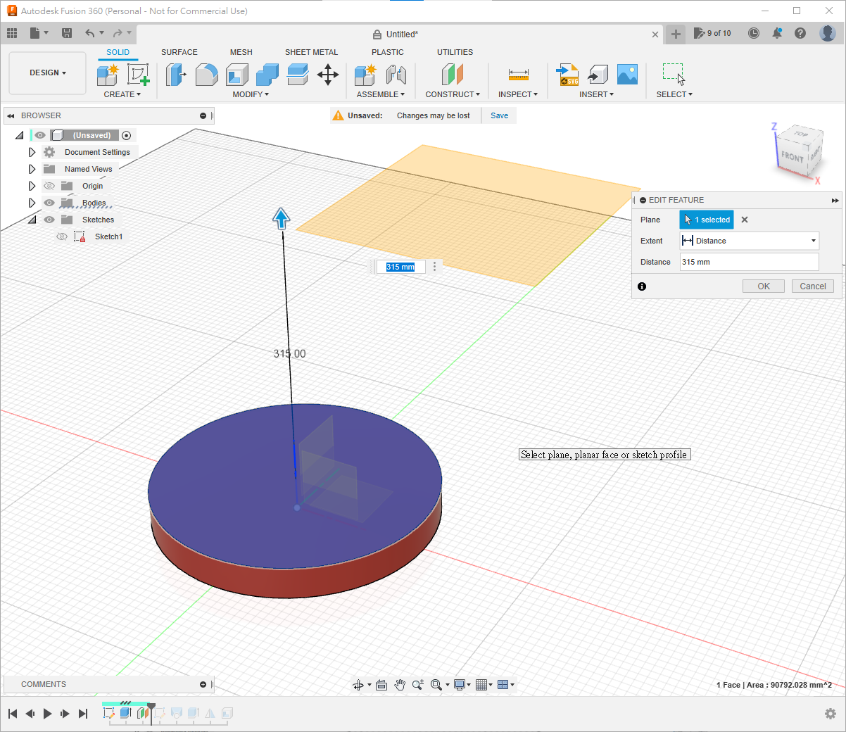
- Offset a plane
315 mmfrom the cylinder top. - On it, draw a
170 mm-diameter circle whose centre is225 mmfrom the origin.
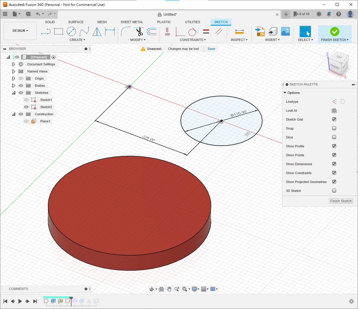
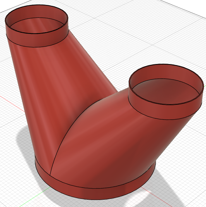
- Loft between the upper circle and cylinder top, with no Rails.
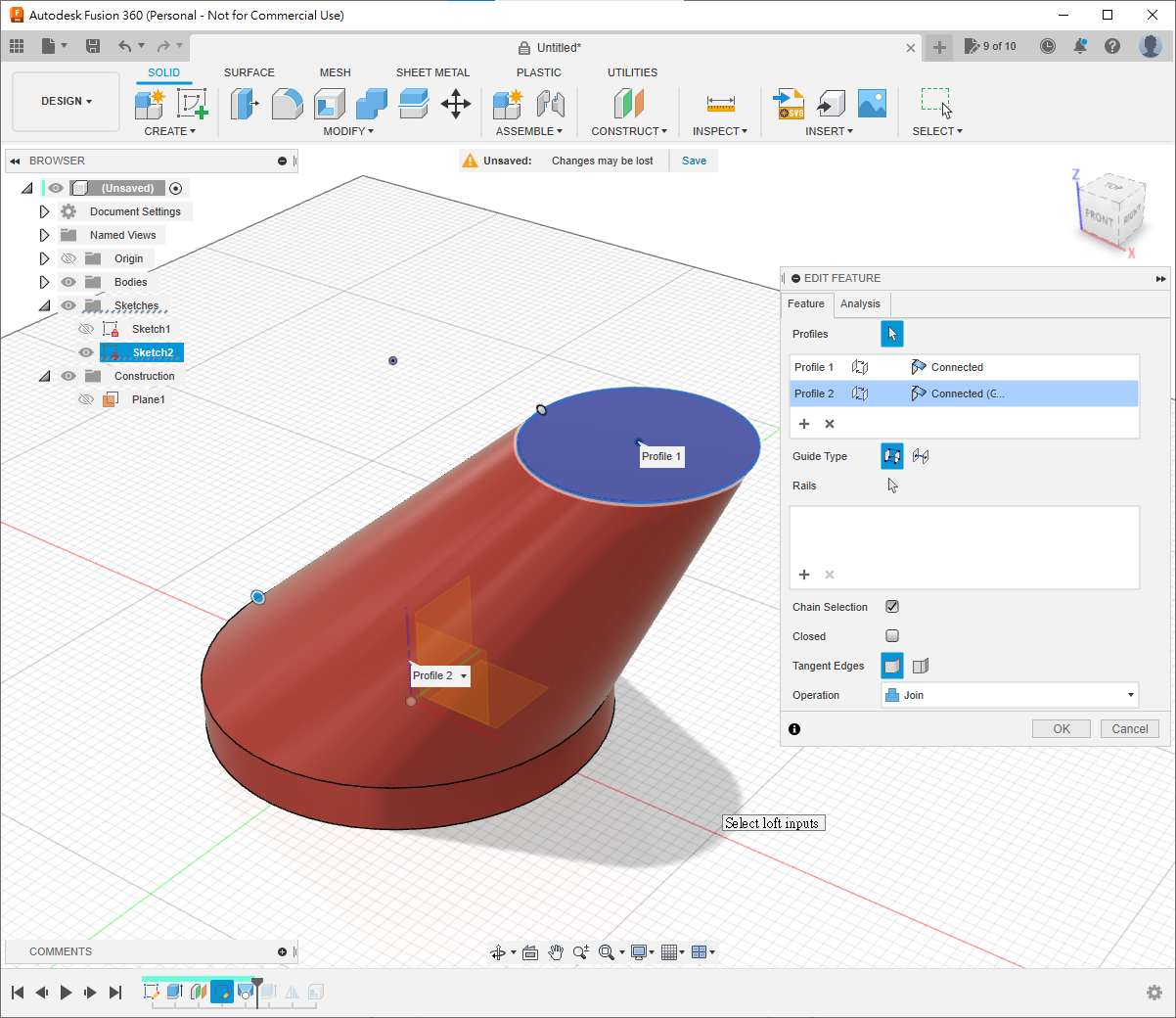
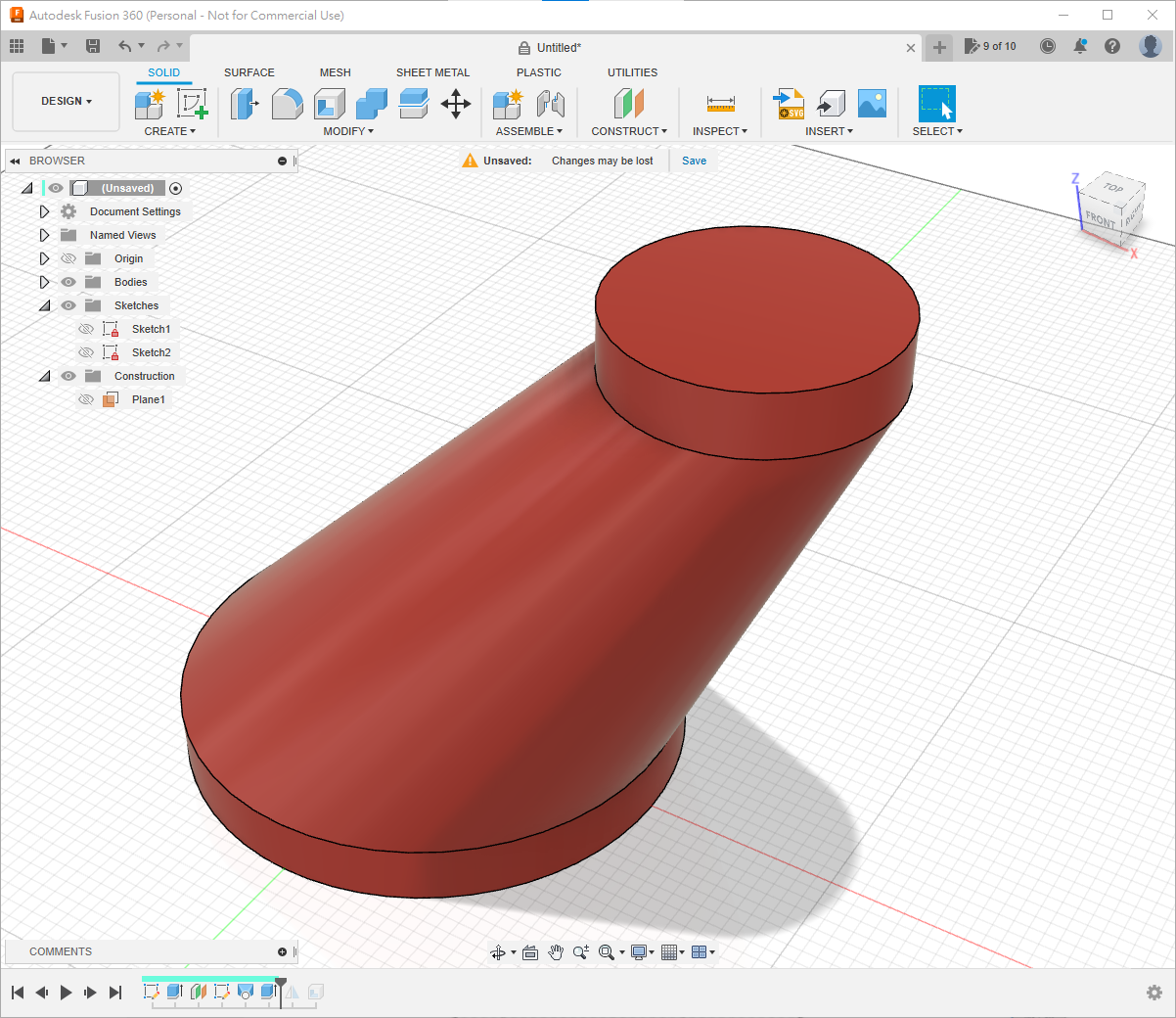
- Extrude the upper circle
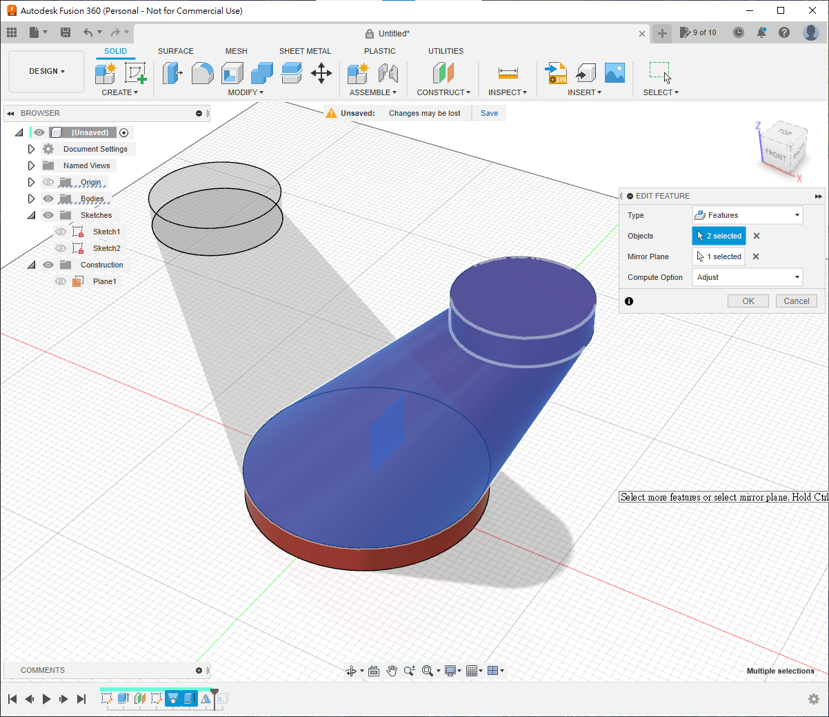
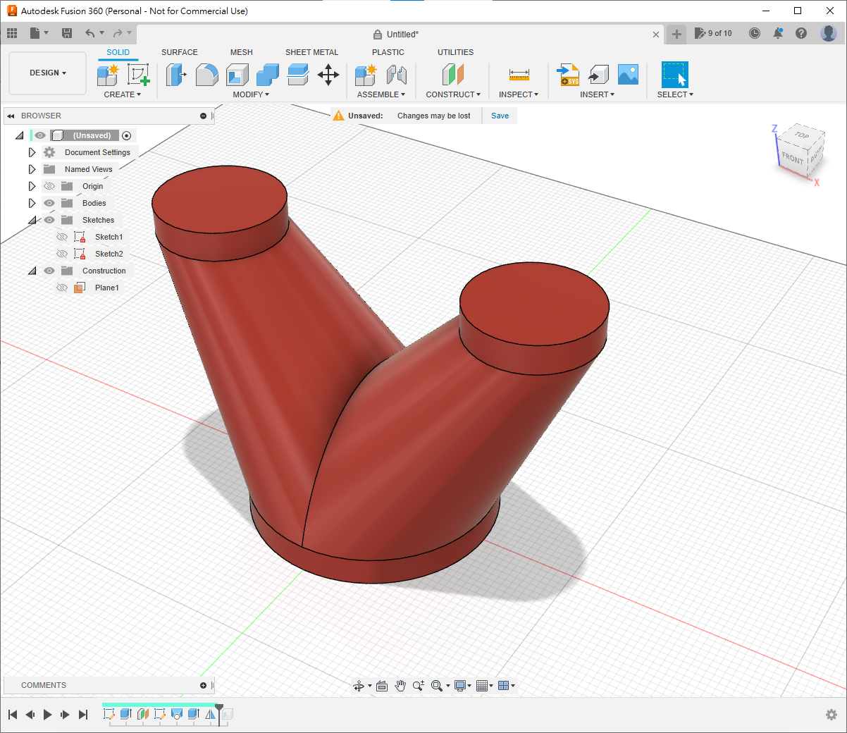
40 mm, then mirror the last two features.
- Shell the model inward by
2 mm, selecting both upper circular faces and the bottom circle as openings.
Exercise 2
Hints

Exercise 3
📝NOTE
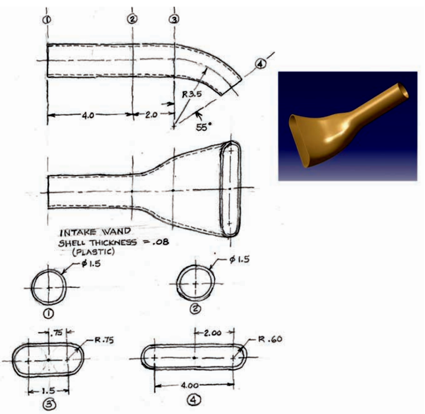
The drawing is dimensioned in inches. Search for Change Active Units and switch the design to inches.
Hints
5. Revolve
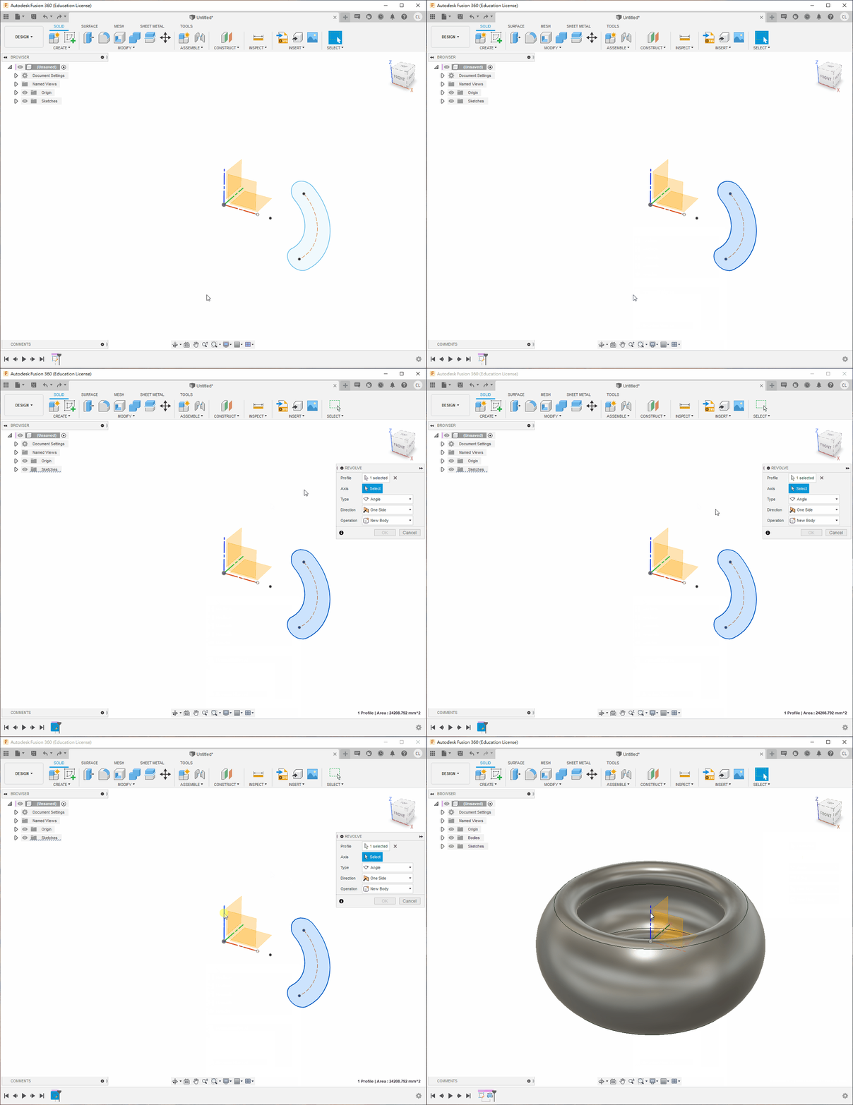
Revolve is the CAD equivalent of turning on a lathe: a profile rotates around an axis to form a solid.
Exercise 1: Printed Bearing
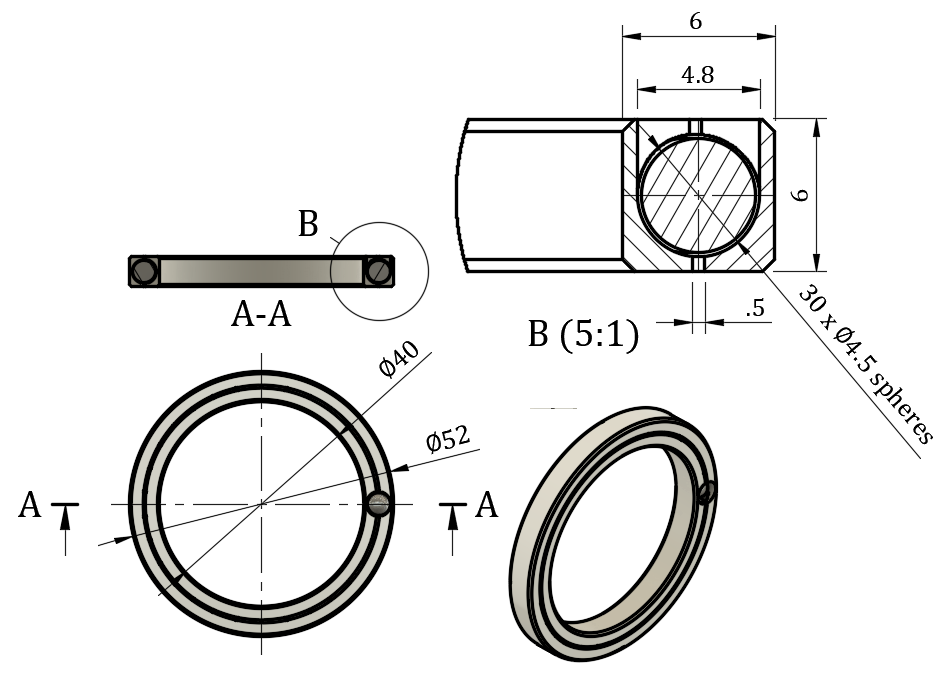
Bearings are standard-sized components and often determine a design's dimensions. Large commercial bearings become expensive quickly. For low-speed, low-precision applications, a printed bearing can use readily available Ø4.5 mm stainless-steel balls.
- On XZ, create a
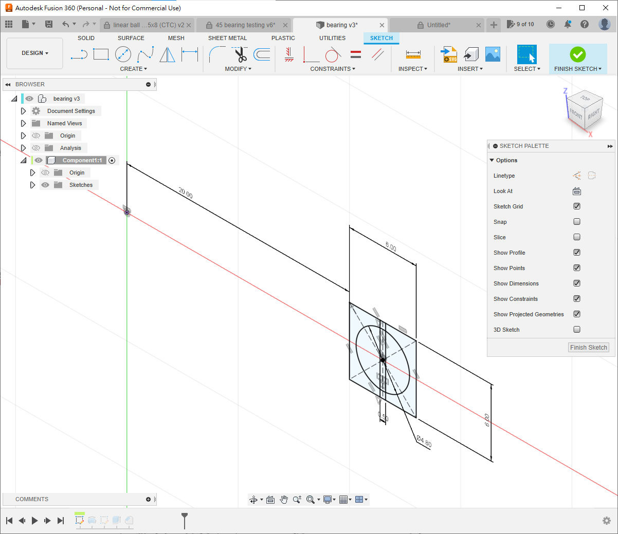
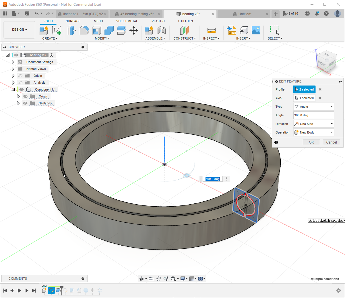
6 × 6 mmcentre rectangle with its edge20 mmfrom the origin. The 20 mm radius gives a 40 mm bore. Add a Ø4.8 mm circle, a centreline and the two symmetric lines with a 0.5 mm gap. - Revolve the solid profile 360° about Z.
⚠️WARNING
If two Revolve commands appear, choose the blue solid command. The orange command creates only a surface.
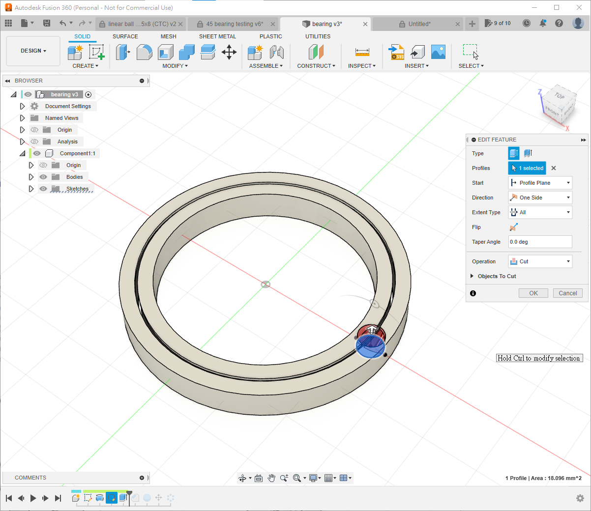
- Sketch on XY. Press
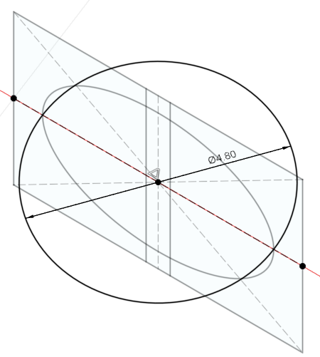
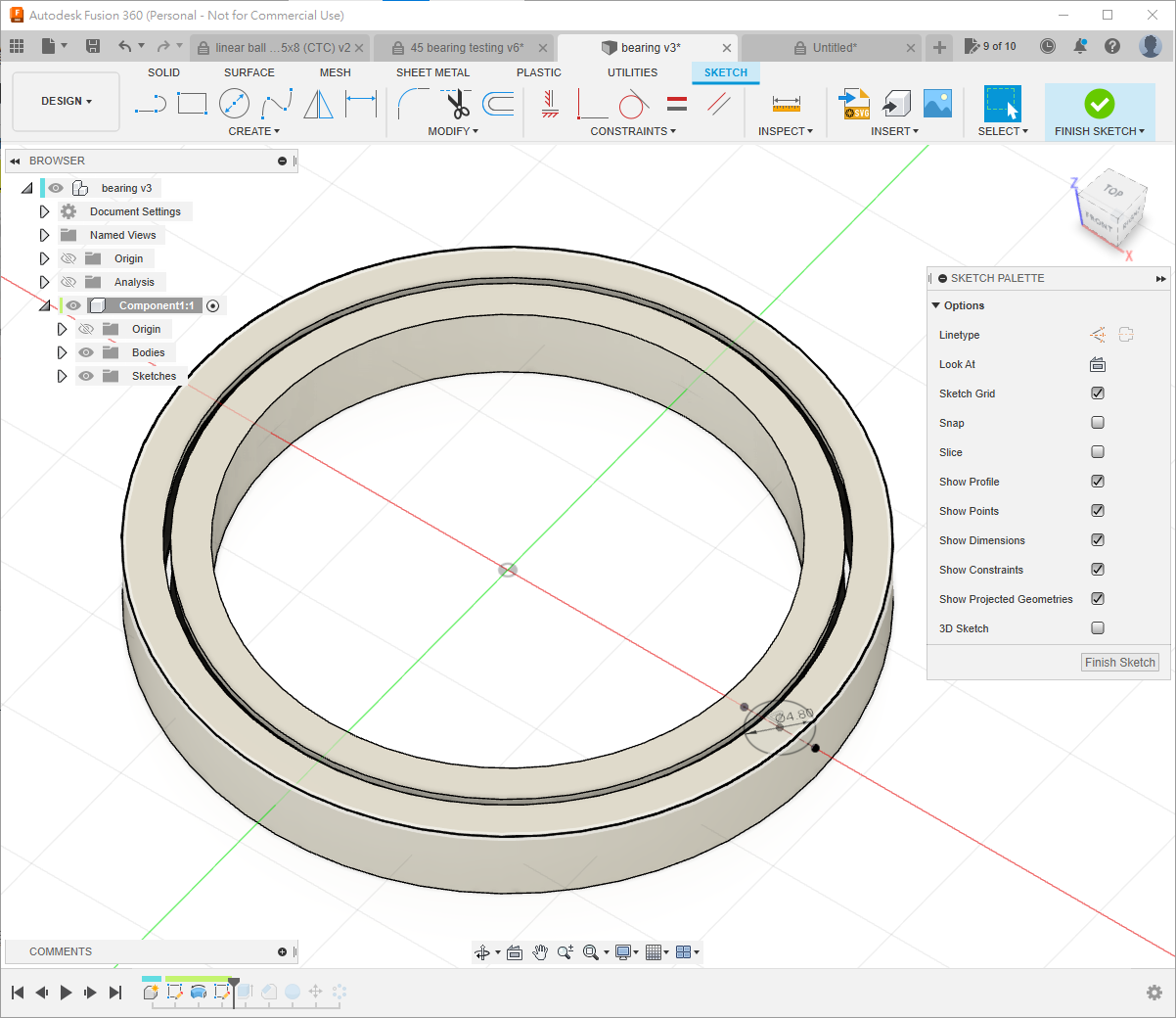
Pto project two edges as points, add a centreline and draw a Ø4.8 mm circle. - Cut the ball channel with Extrude.
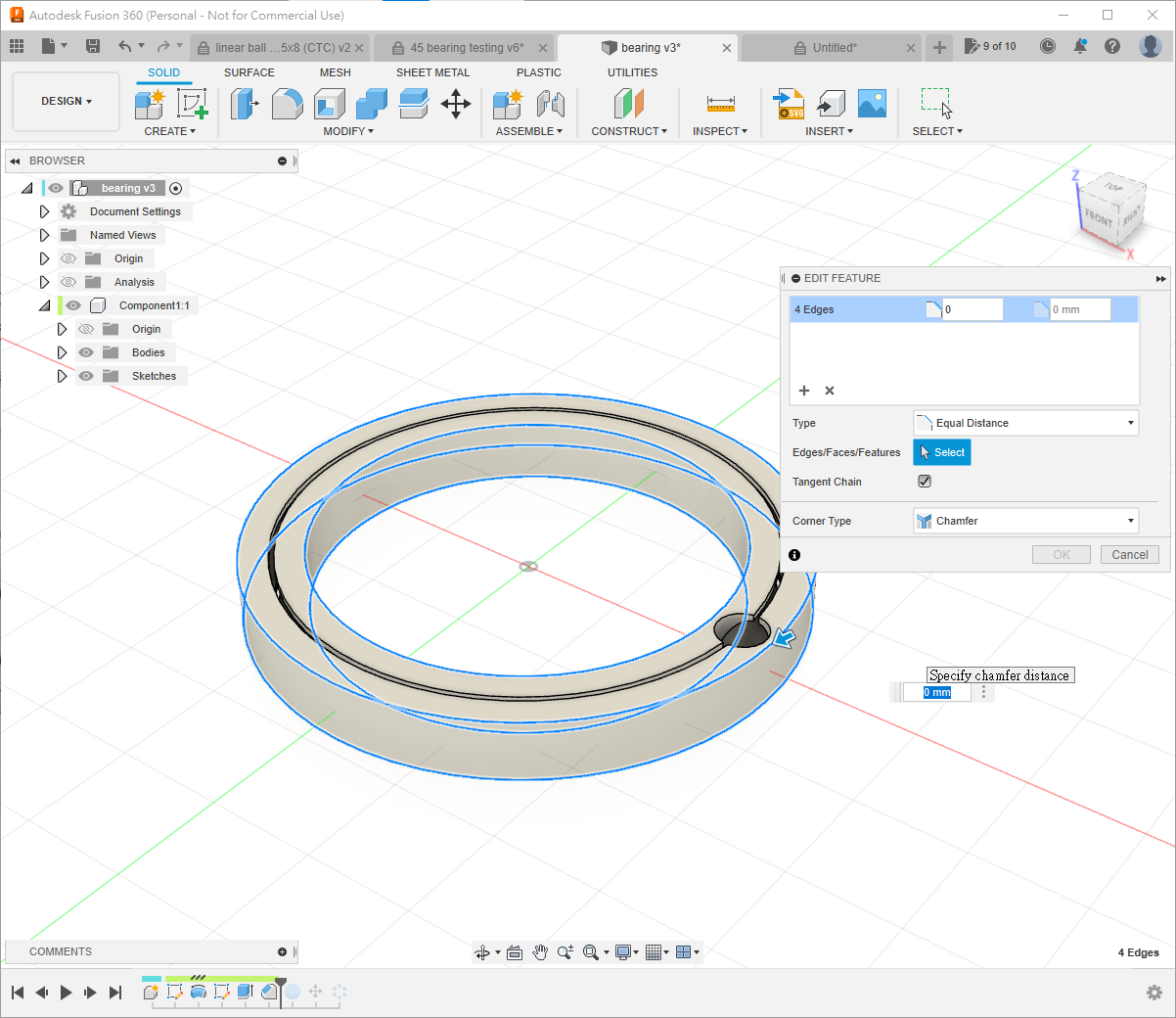
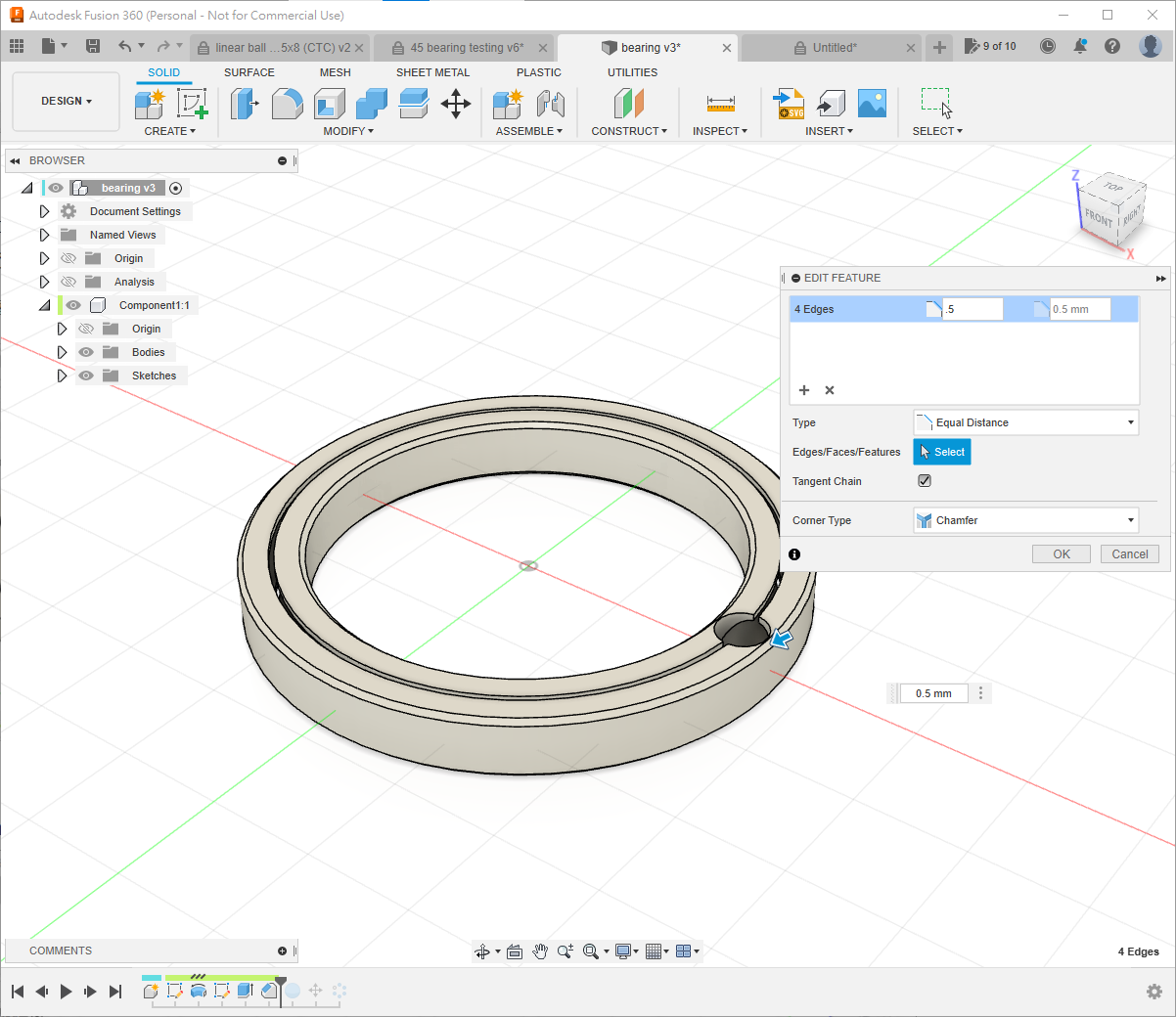
- Chamfer the four circular edges by
0.5 mm.
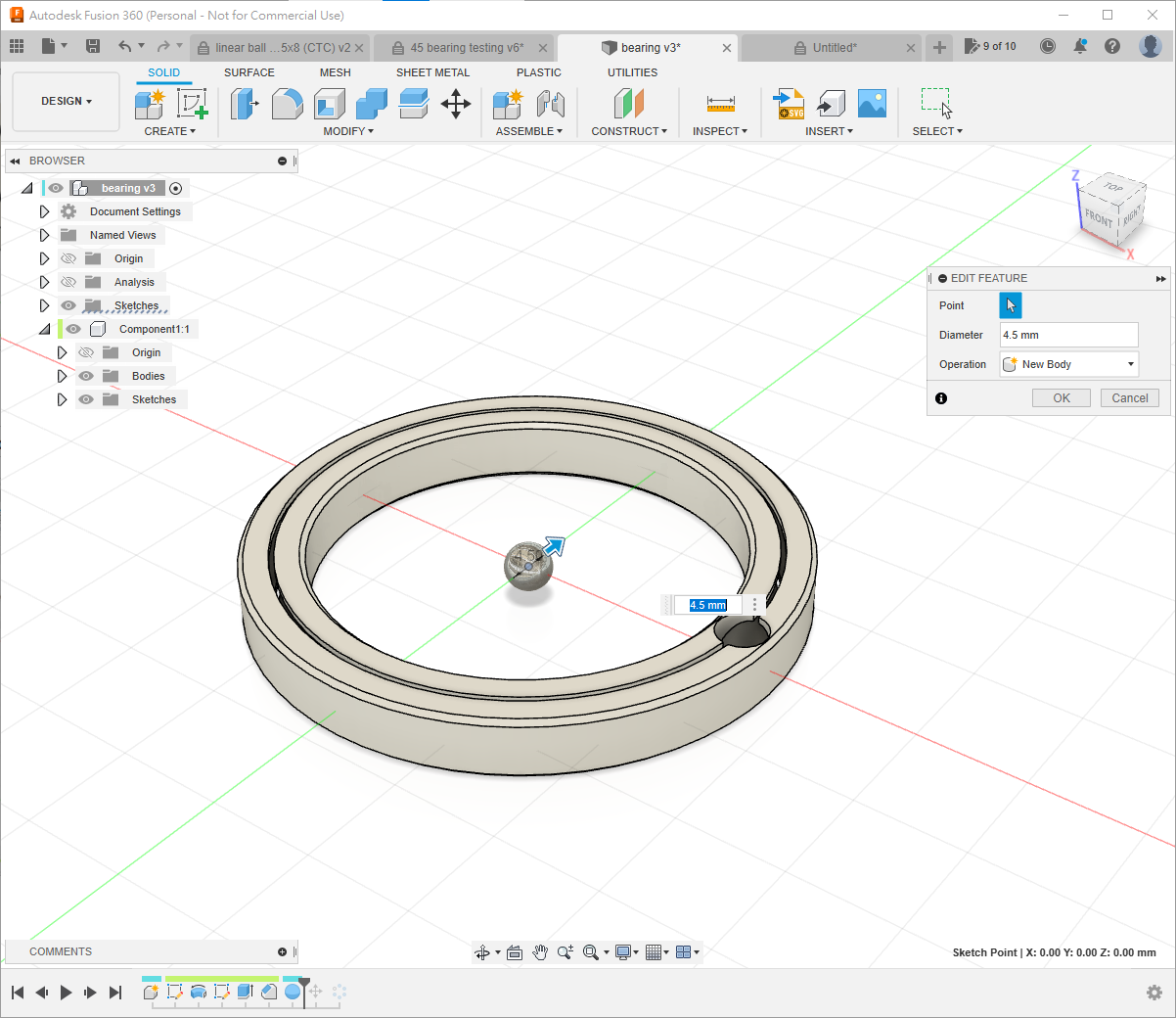
- Use
Sphereto create a Ø4.5 mm ball at the origin. - Move it
23 mmalong X.
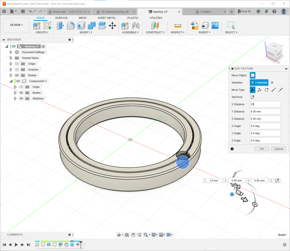
- Use
Circular Patternto make 30 balls around the axis.
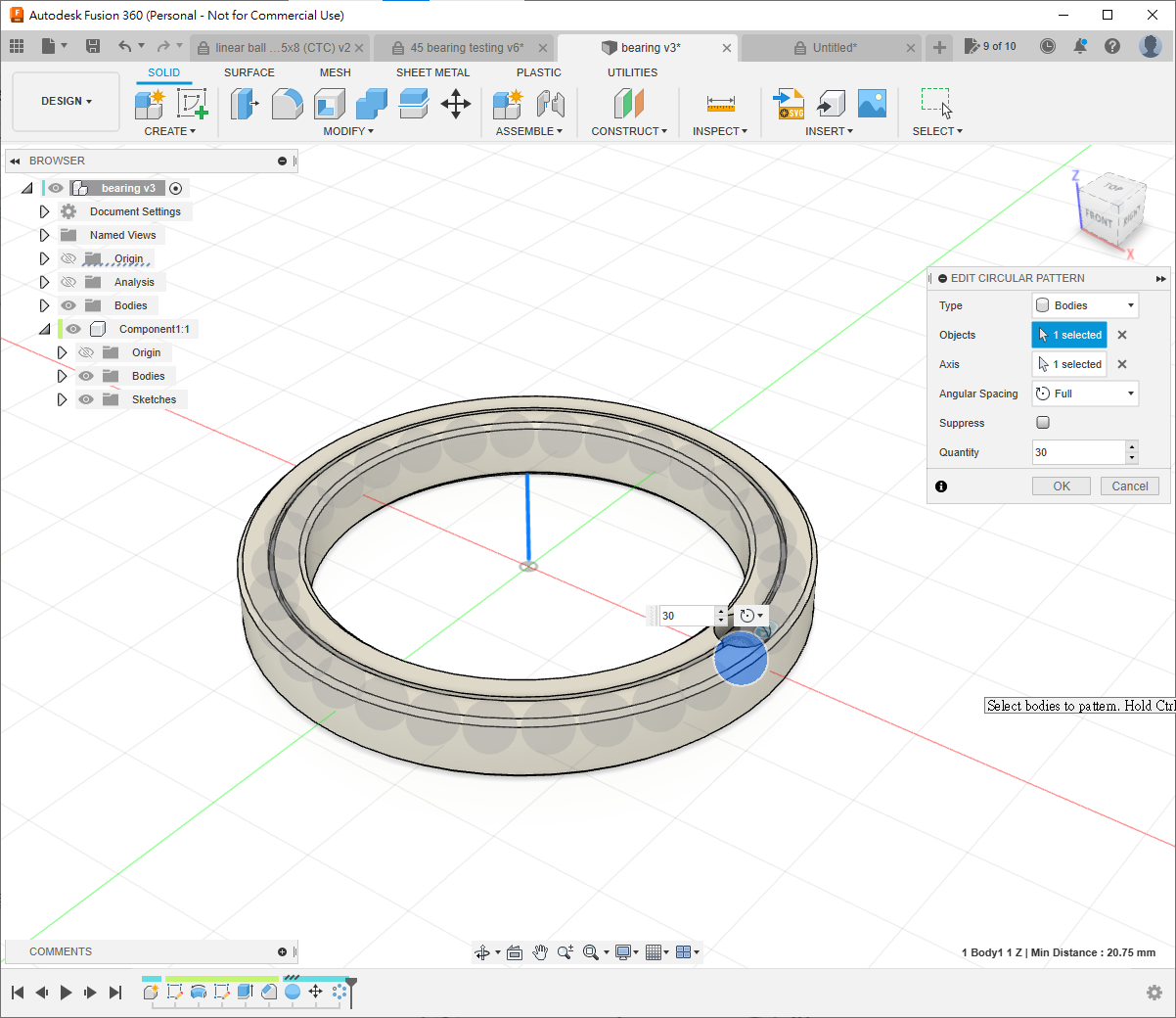
Exercise 2
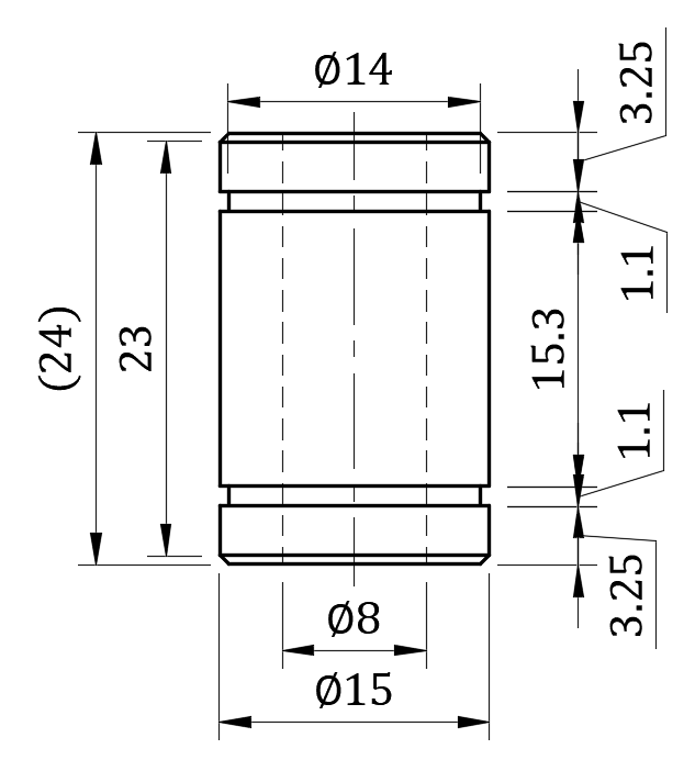
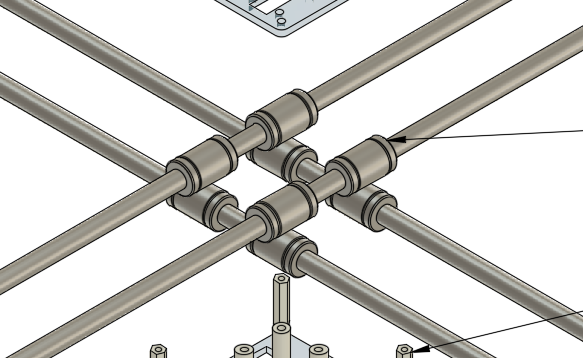
Model this common 8 mm linear bearing used in 3D printers.
6. Sweep
Sweep moves a profile along a path.
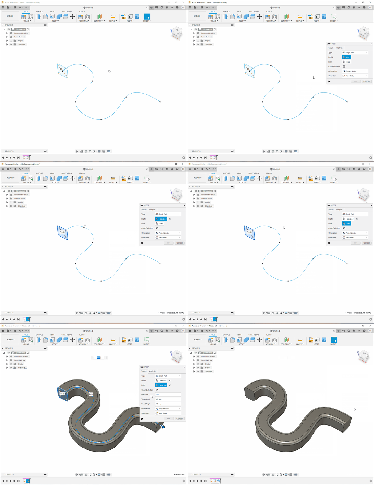
Exercise 1
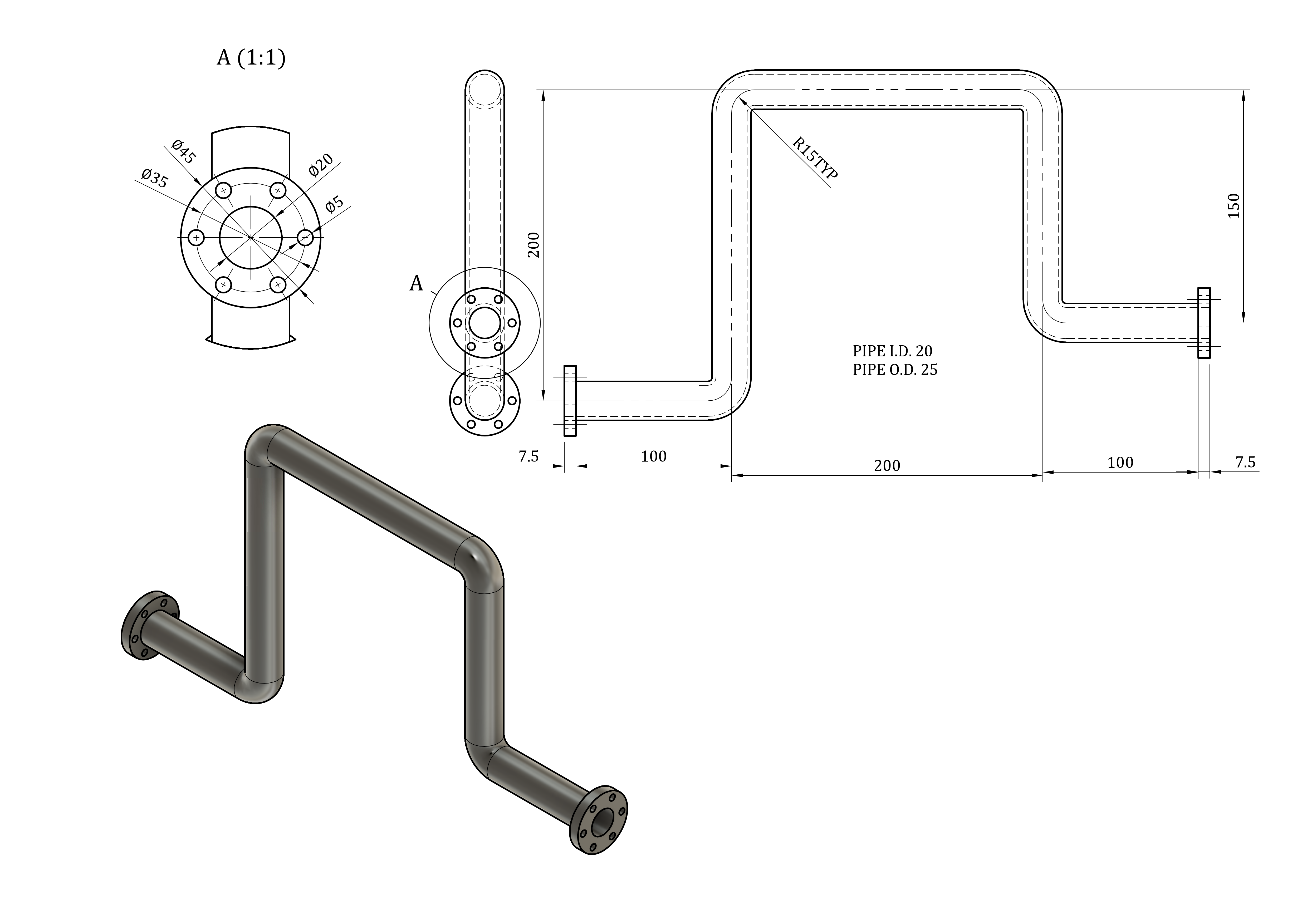
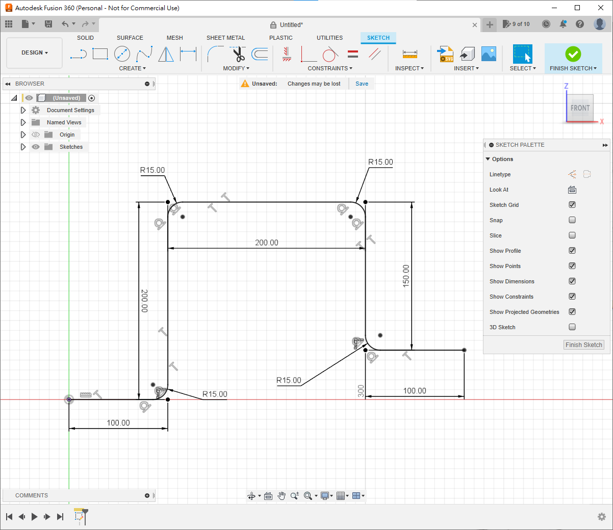
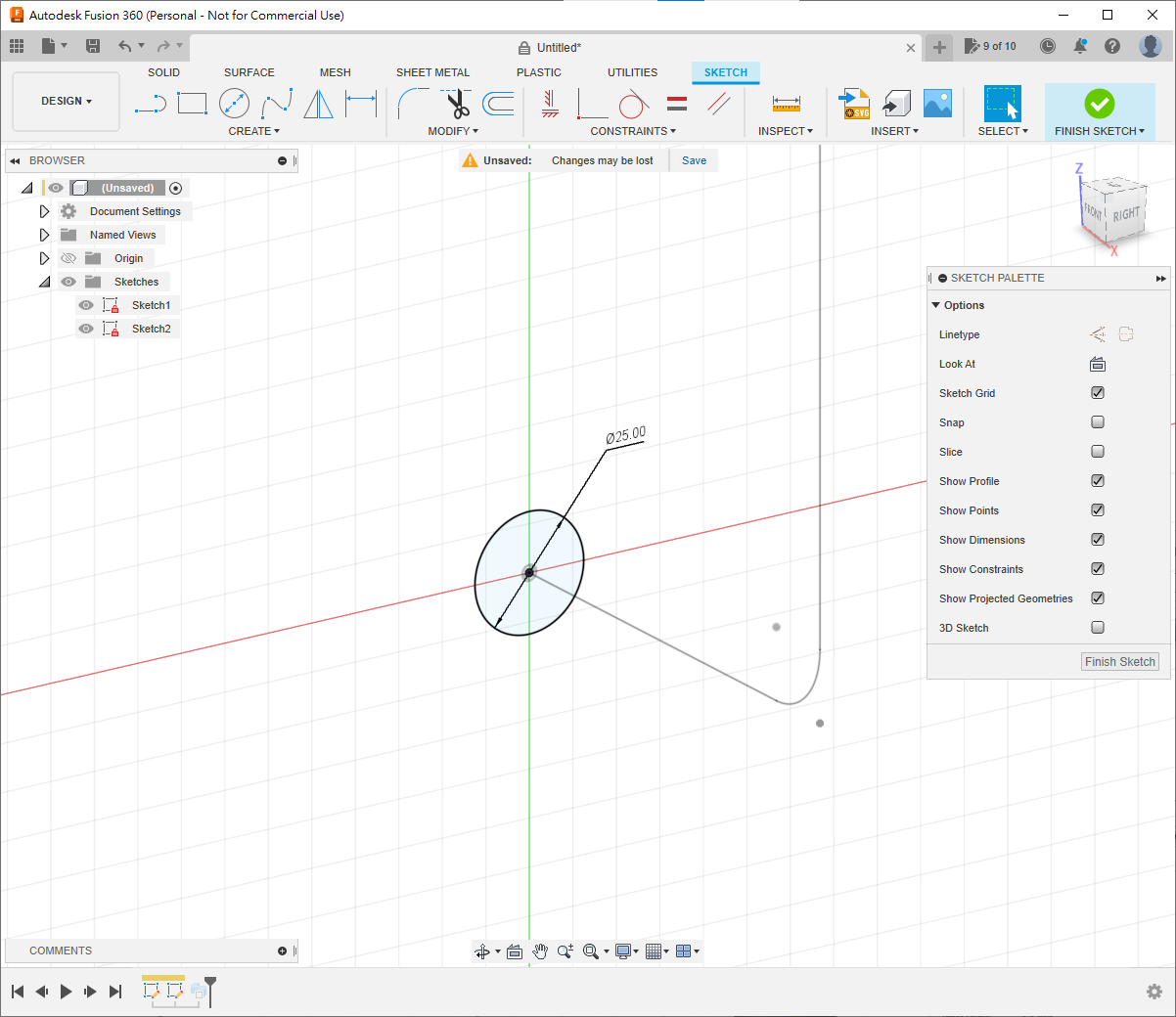
- On XZ, sketch the pipe centreline to the drawing dimensions.
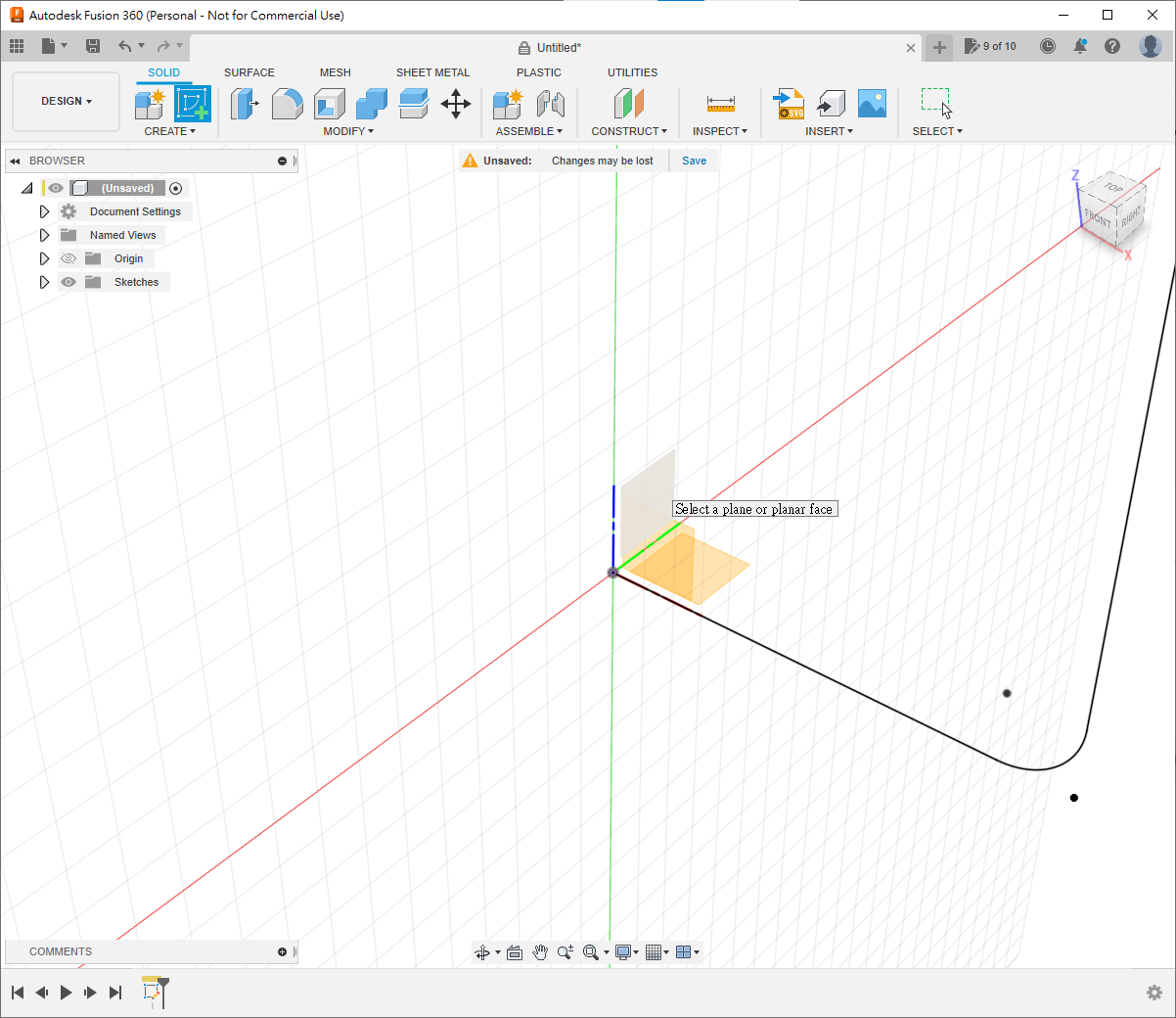
- On YZ, sketch the Ø25 mm outside profile.
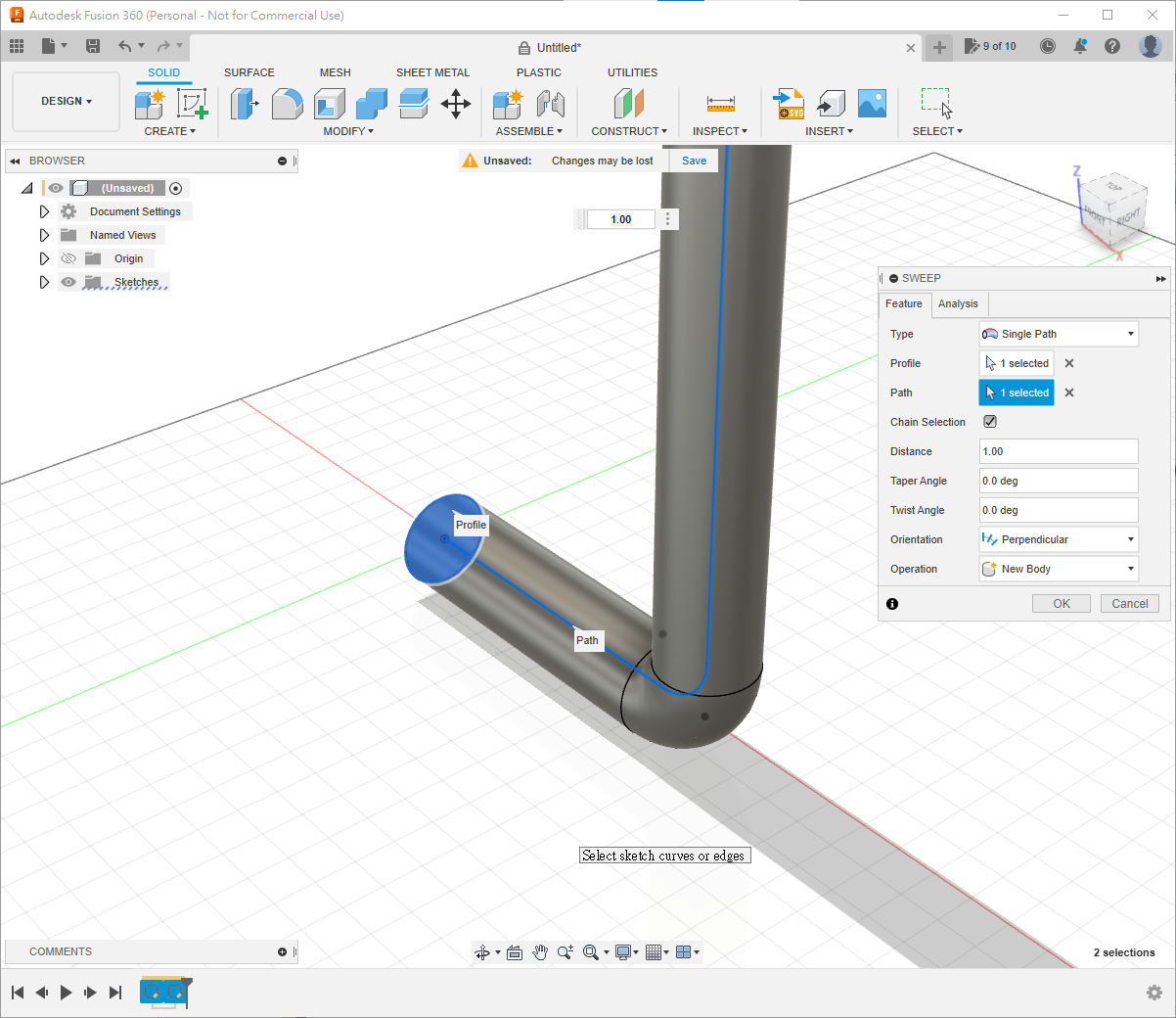
- Sweep the circle as Profile along the centreline Path.
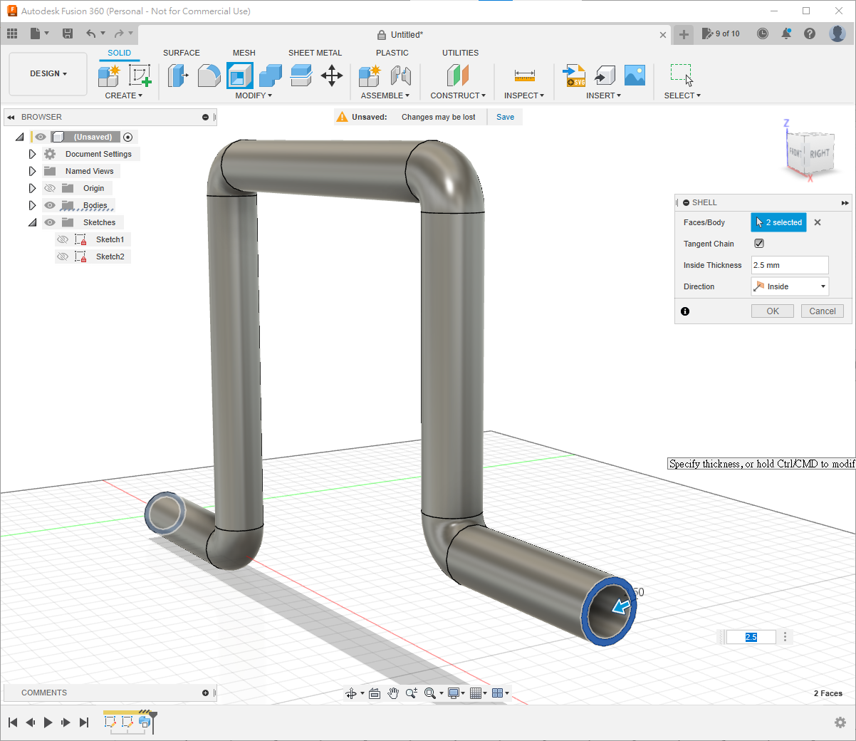
- Shell through both ends with
2.5 mmwall thickness.
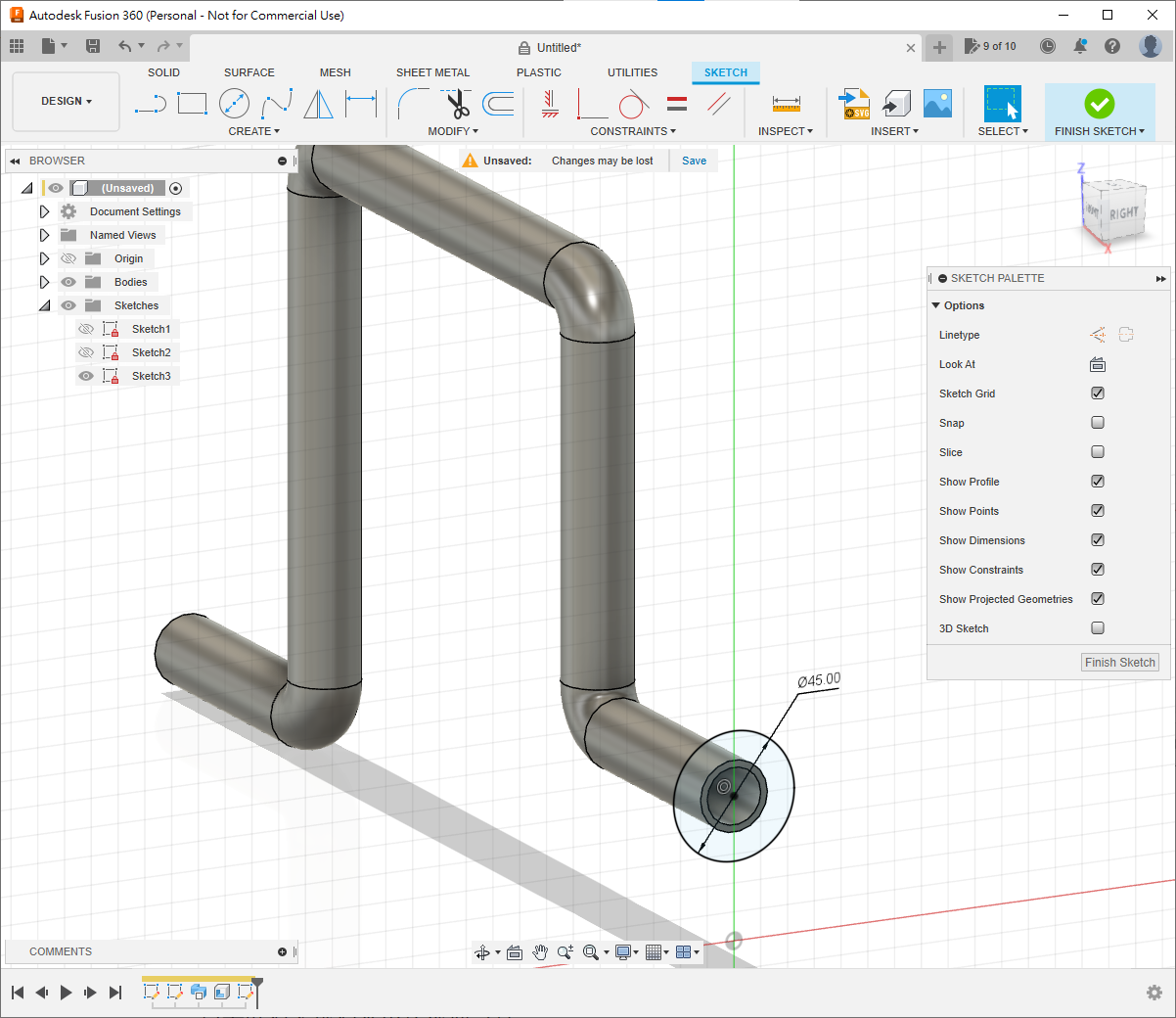
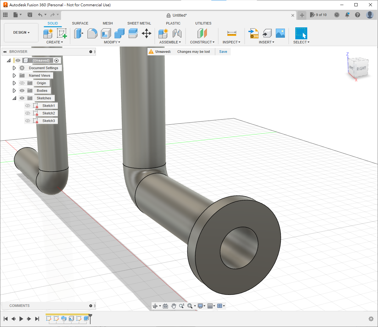
- On one end, sketch the Ø45 mm flange and extrude it
7.5 mm.
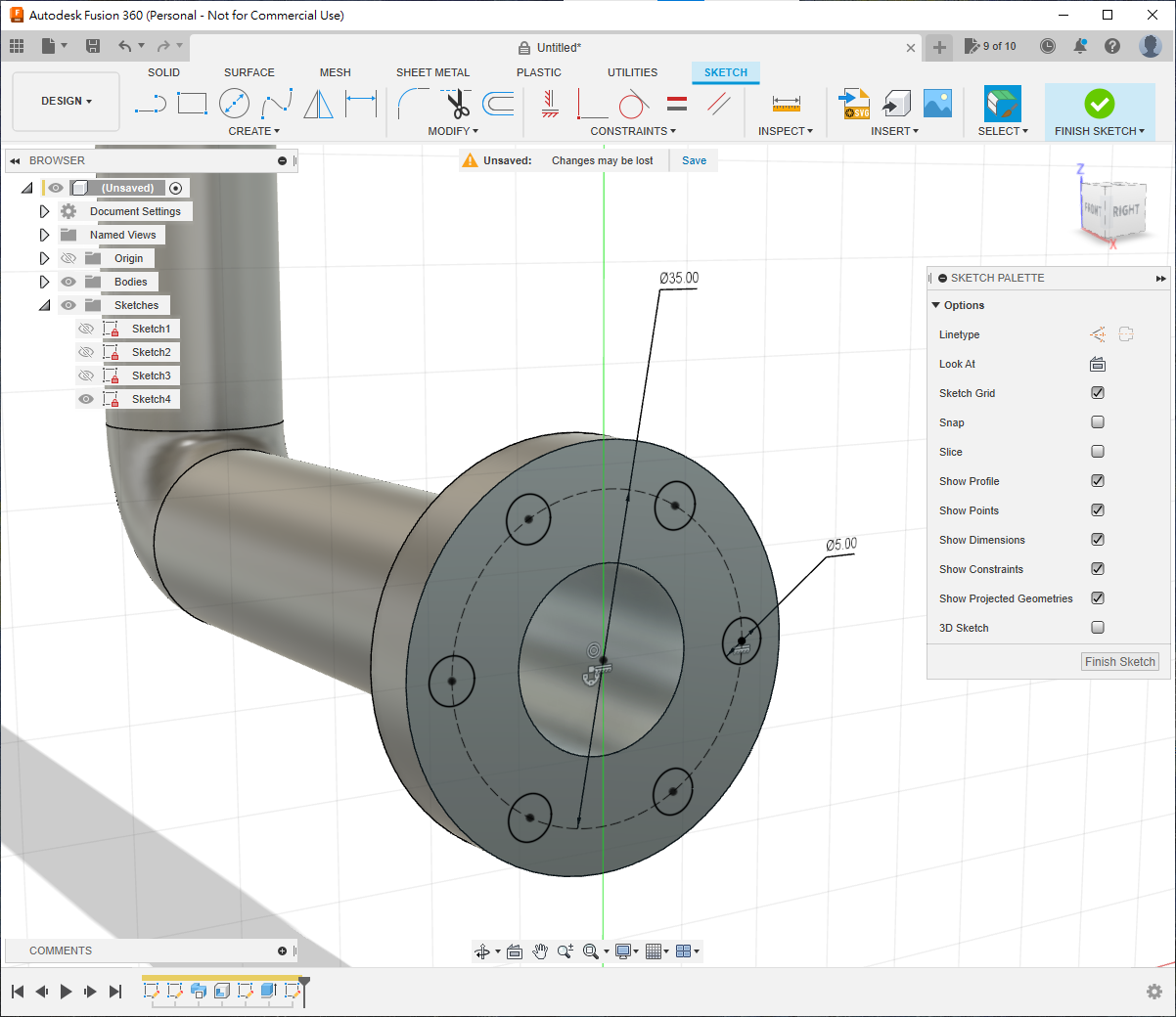
- Sketch the six mounting holes on the flange.
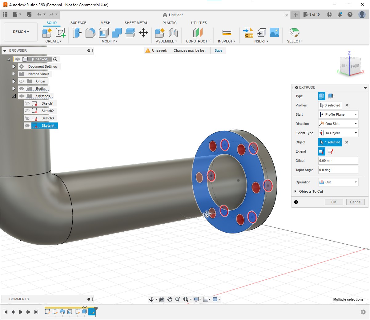
- Cut them with Extrude set to
To Object, selecting the rear flange face.
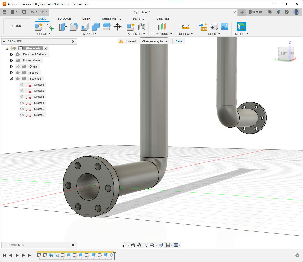
- Repeat on the other end.
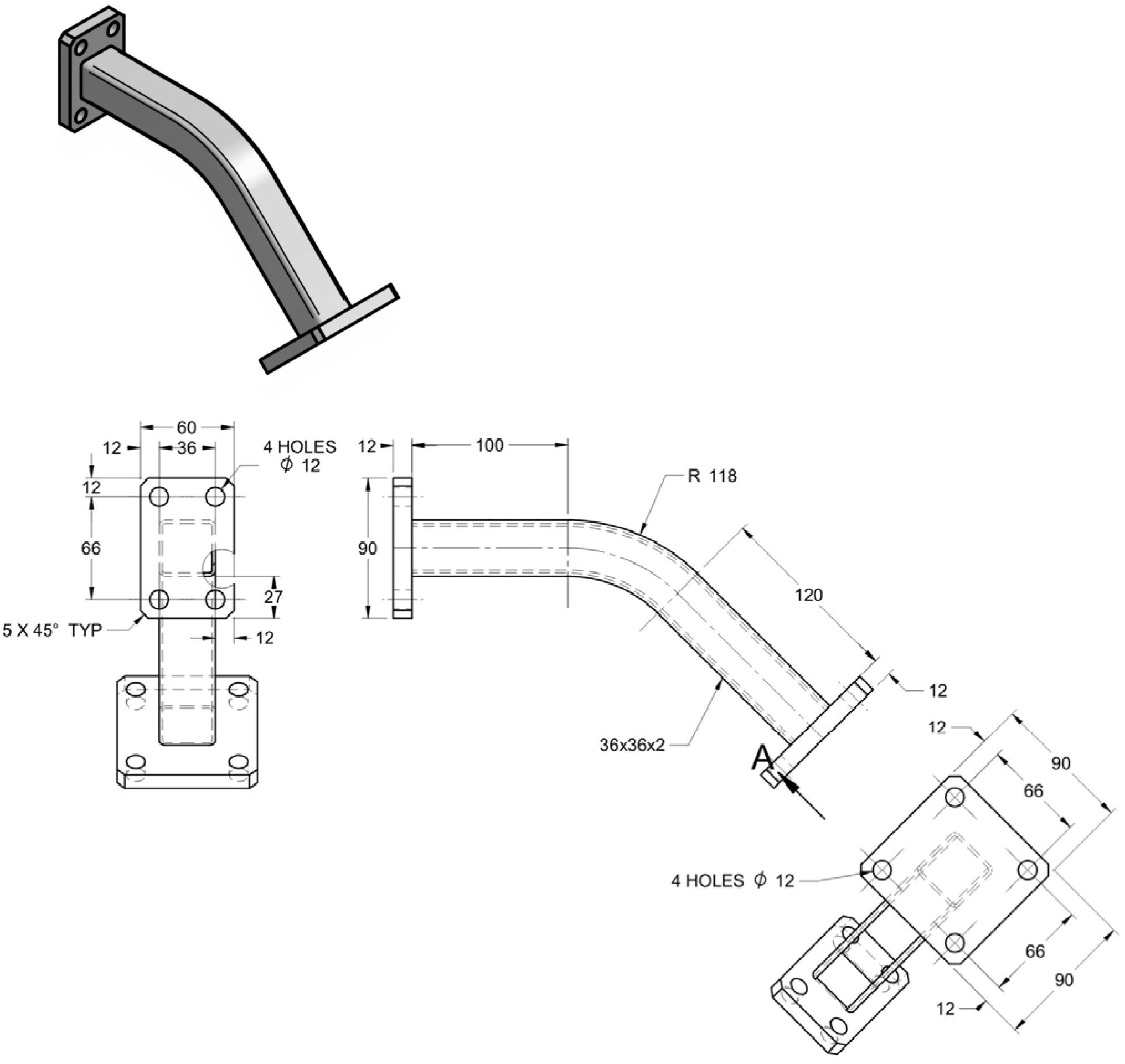
Exercise 2
💡TIP
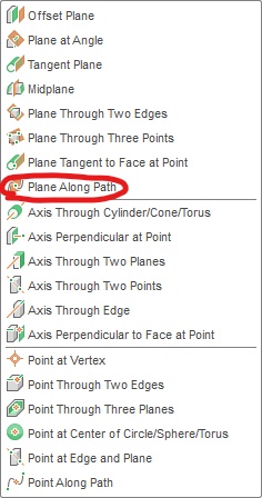
This exercise requires Plane Along Path.
7. Combined Exercise
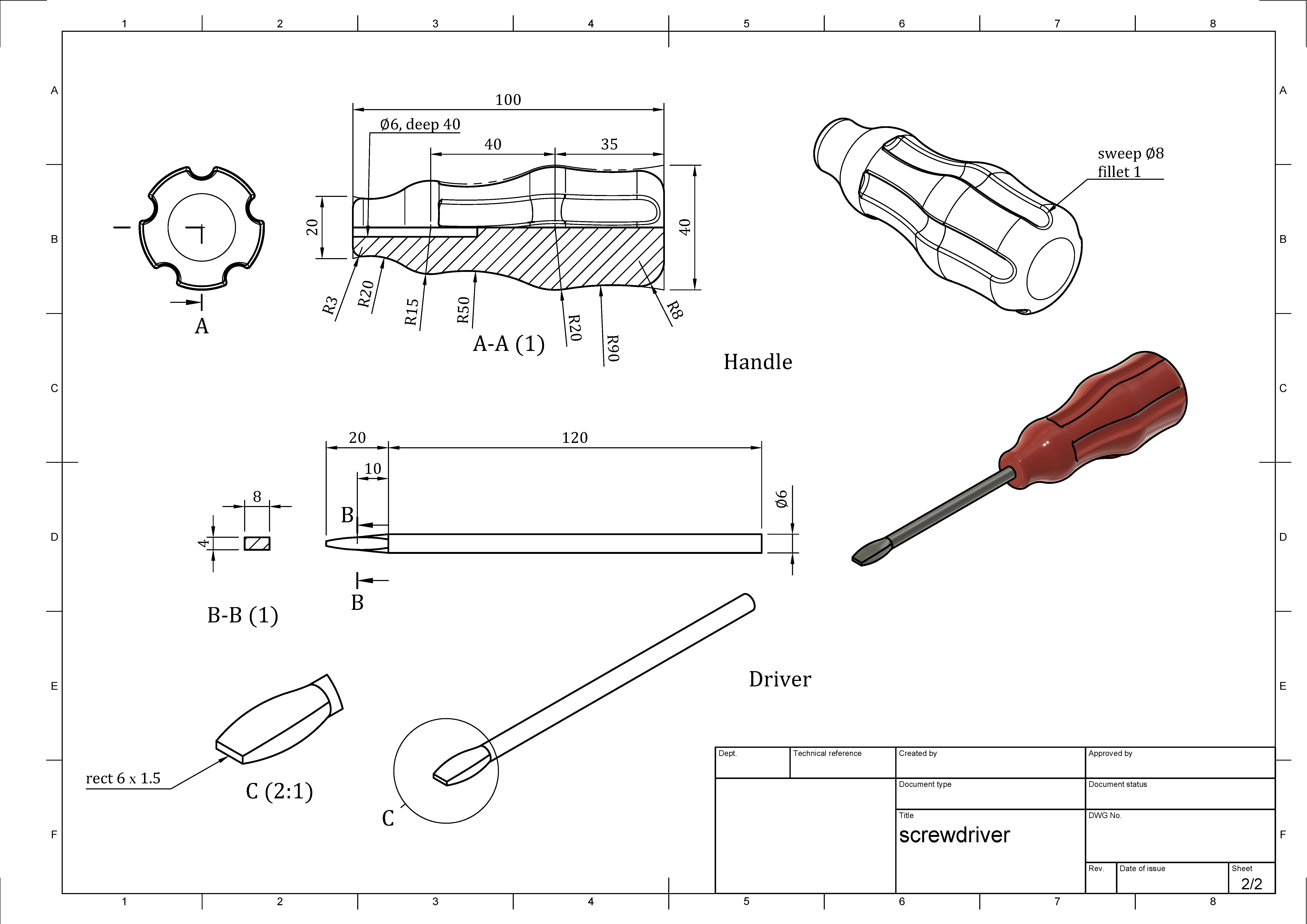
This final problem combines several modelling tools.
Exercise 1
Hints
Translation notice: This English page was generated automatically by AI and has not yet been reviewed by a human. It will be checked and revised page by page when time permits.