Six-Legged Walking Linkage Robot
ℹ️INFO
This advanced walking-linkage robot is designed to give you extensive practice with Fusion 360 joints.
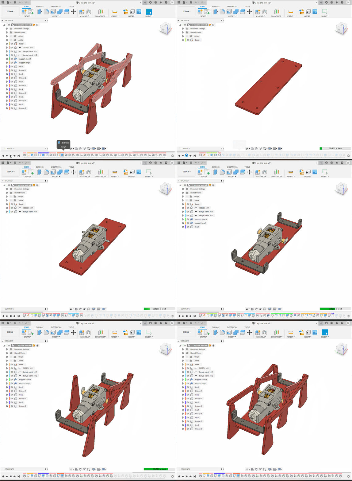
Video demonstration
Step 1: Overall Plan
Create a new design and model only one side of the robot first. Later, derive it into another design and duplicate it. This avoids losing joints when the model is reorganised into layers.
Step 2: Base
- Create and activate a component named
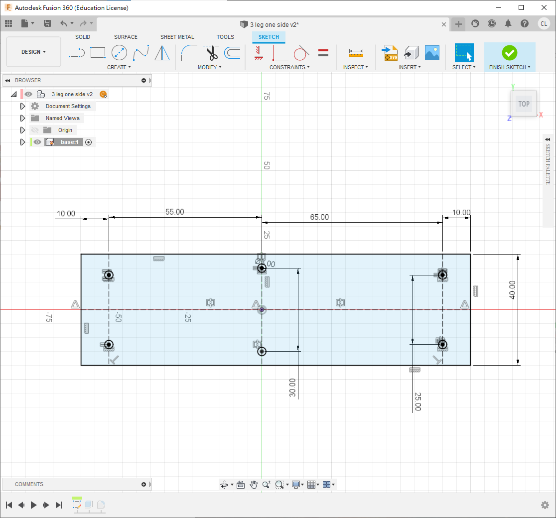
base. - Create a sketch and draw the profile shown.
- Open
Change Parametersand createthickness = 3 mm. - Extrude the sketch by
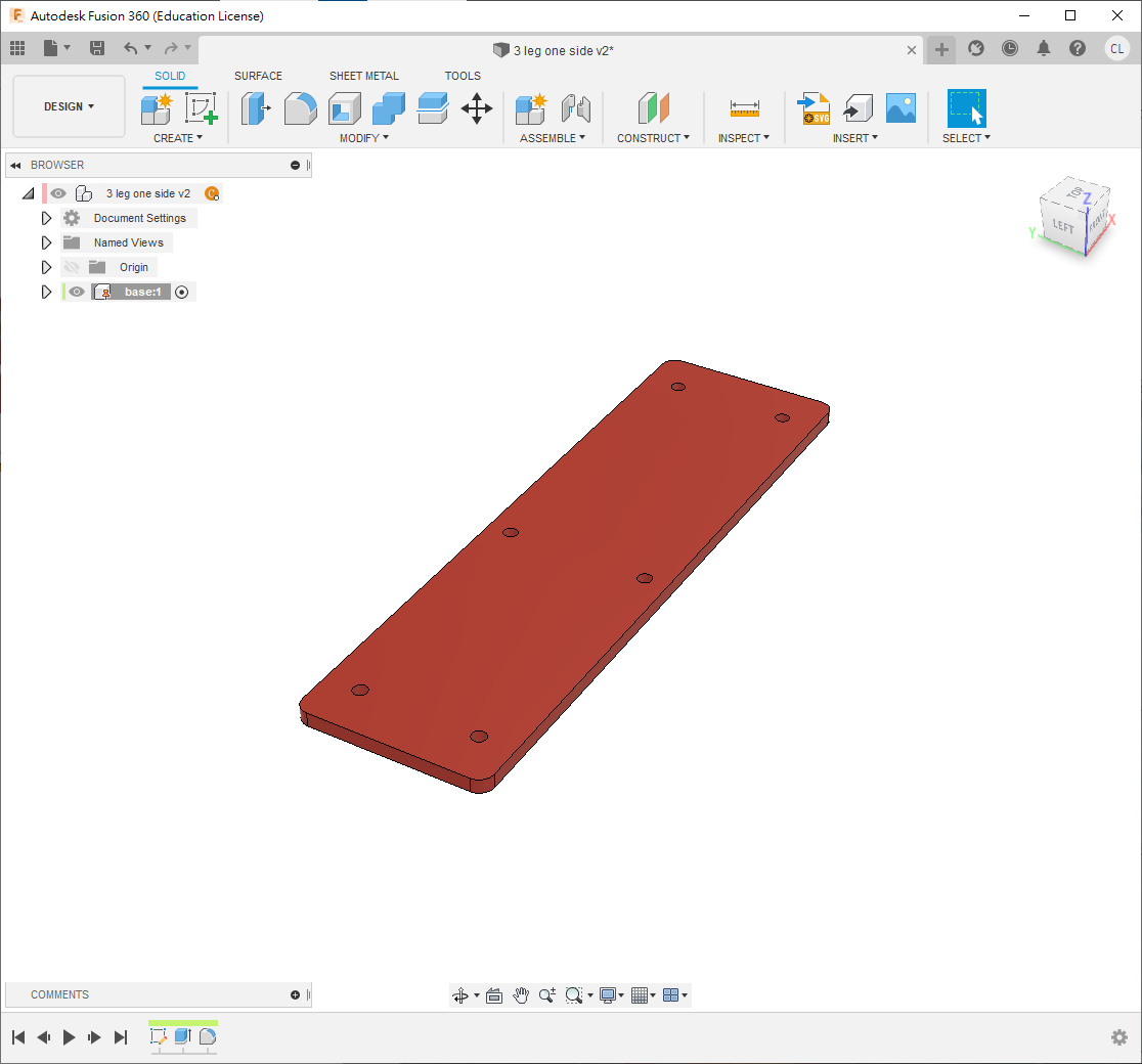
thickness, then apply3 mmfillets to the four corners.
Step 3: Gearbox
- Use
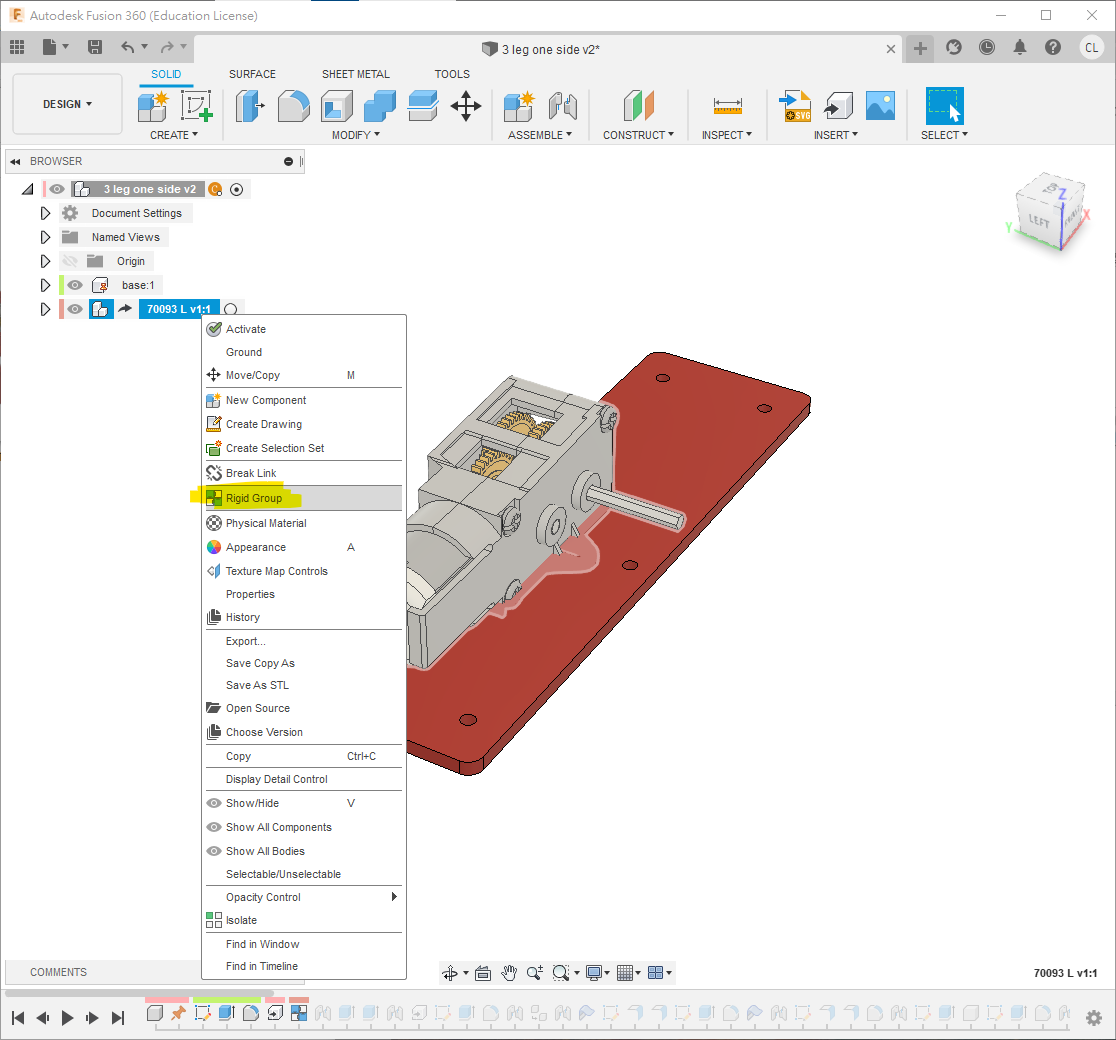
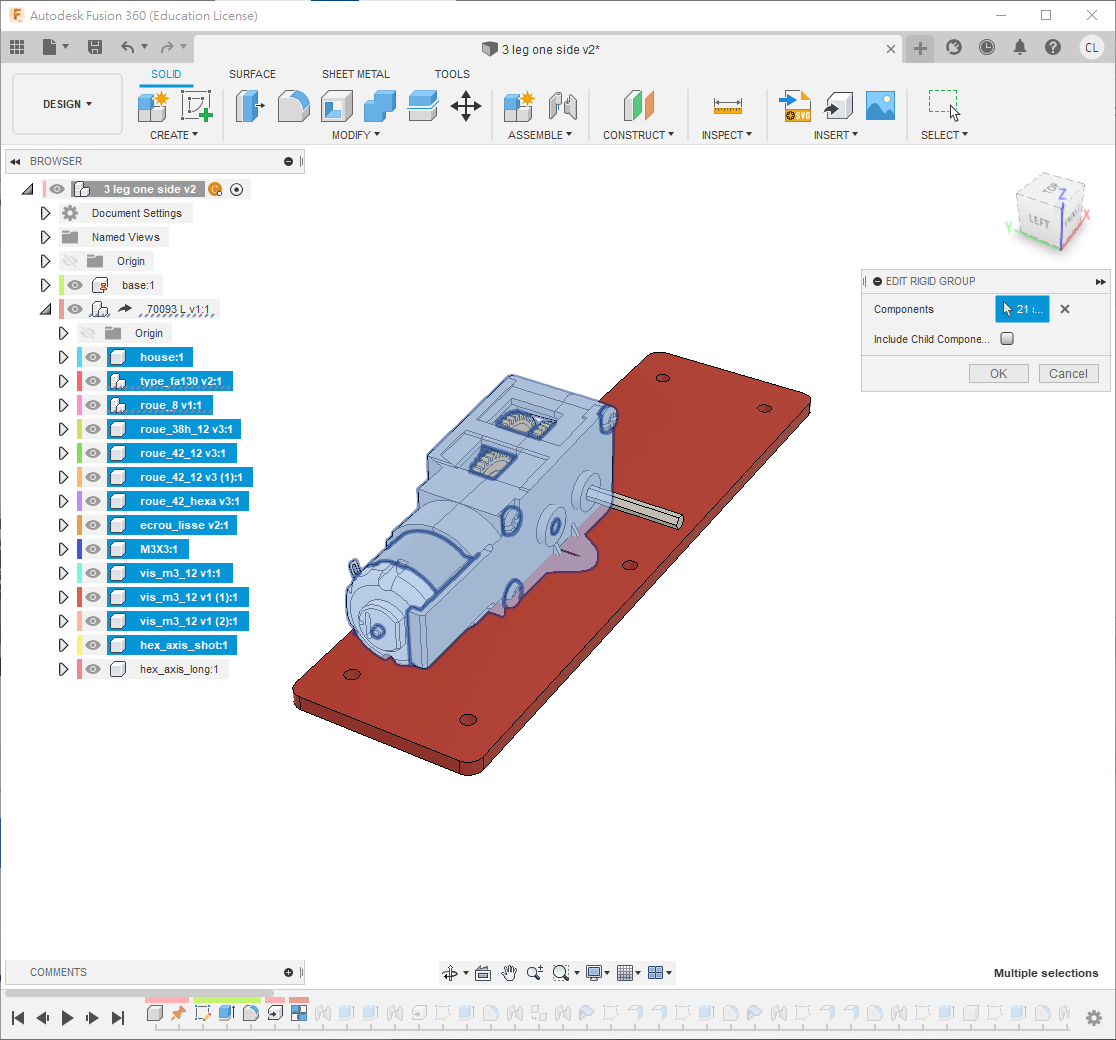
Insert Deriveto insert the 70093 gearbox STEP model. - Right-click the gearbox and choose
Rigid Group. - Hold
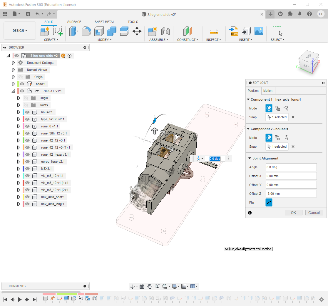
Ctrland select the gears, motor and casing, excluding the long output shaft. - Attach the remaining long shaft to the casing with a Revolute joint.
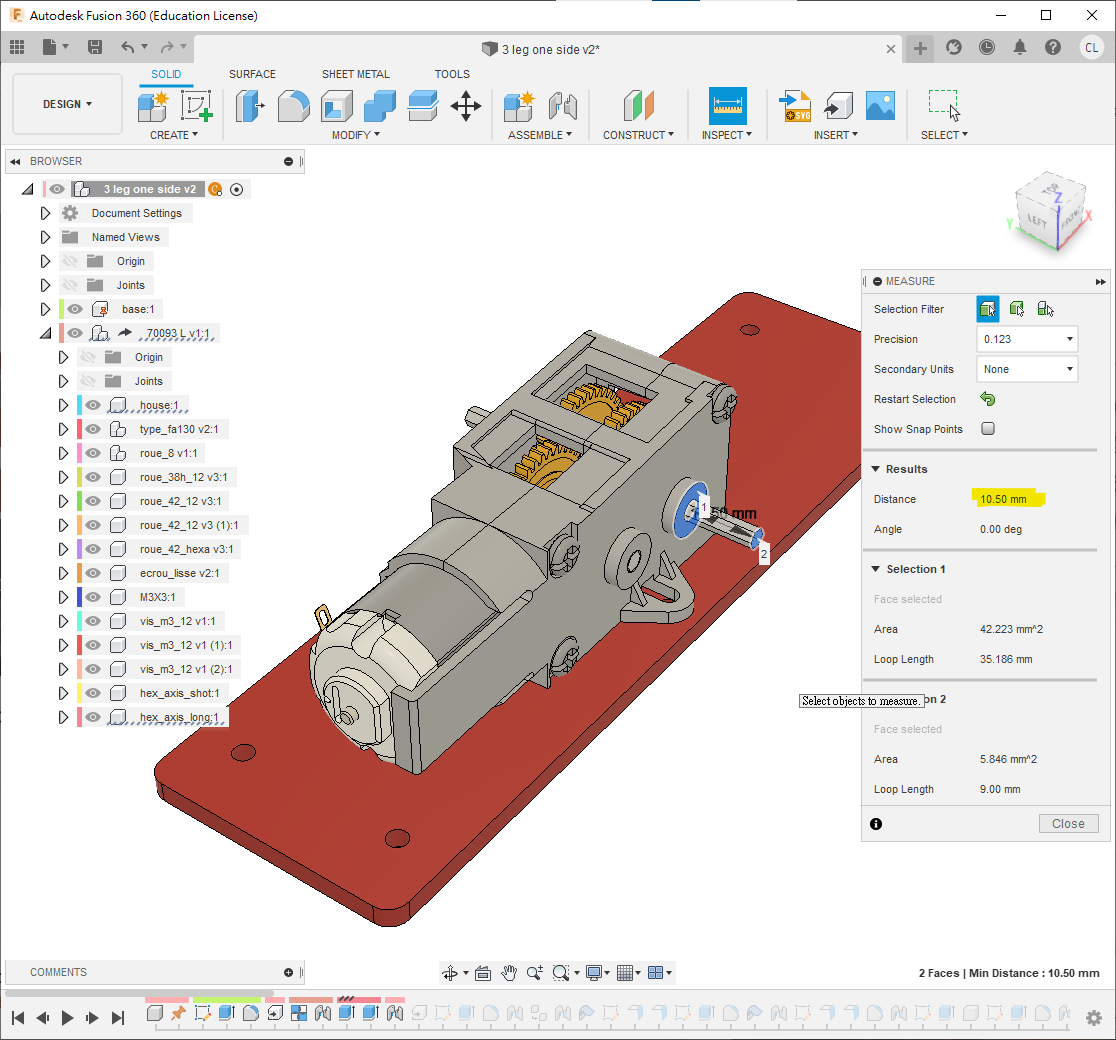
- Extend or shorten both shaft ends with
Eso that each projects10.5 mmfrom the casing.
Step 4: Cranks
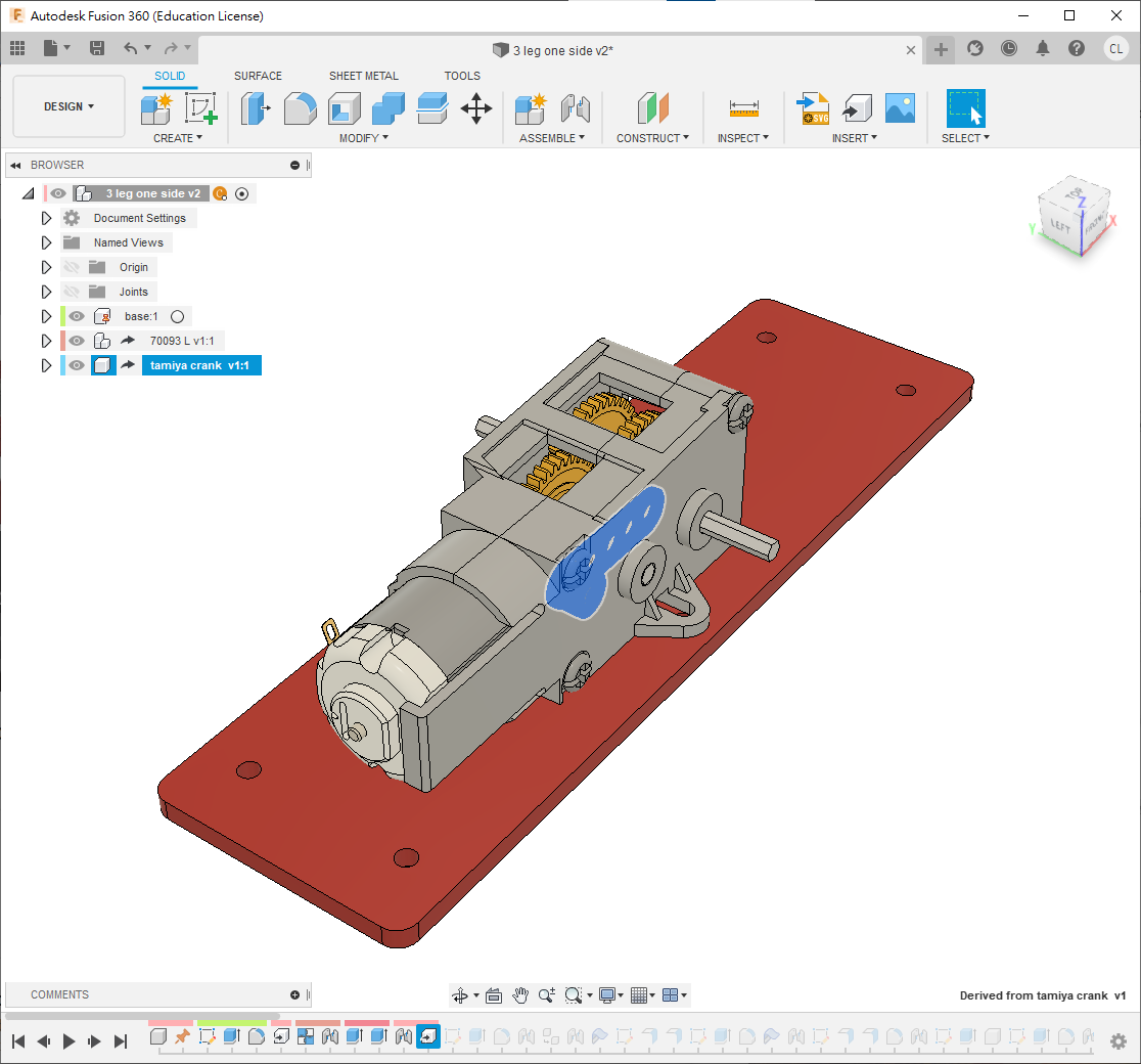
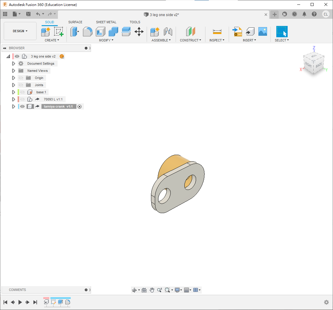
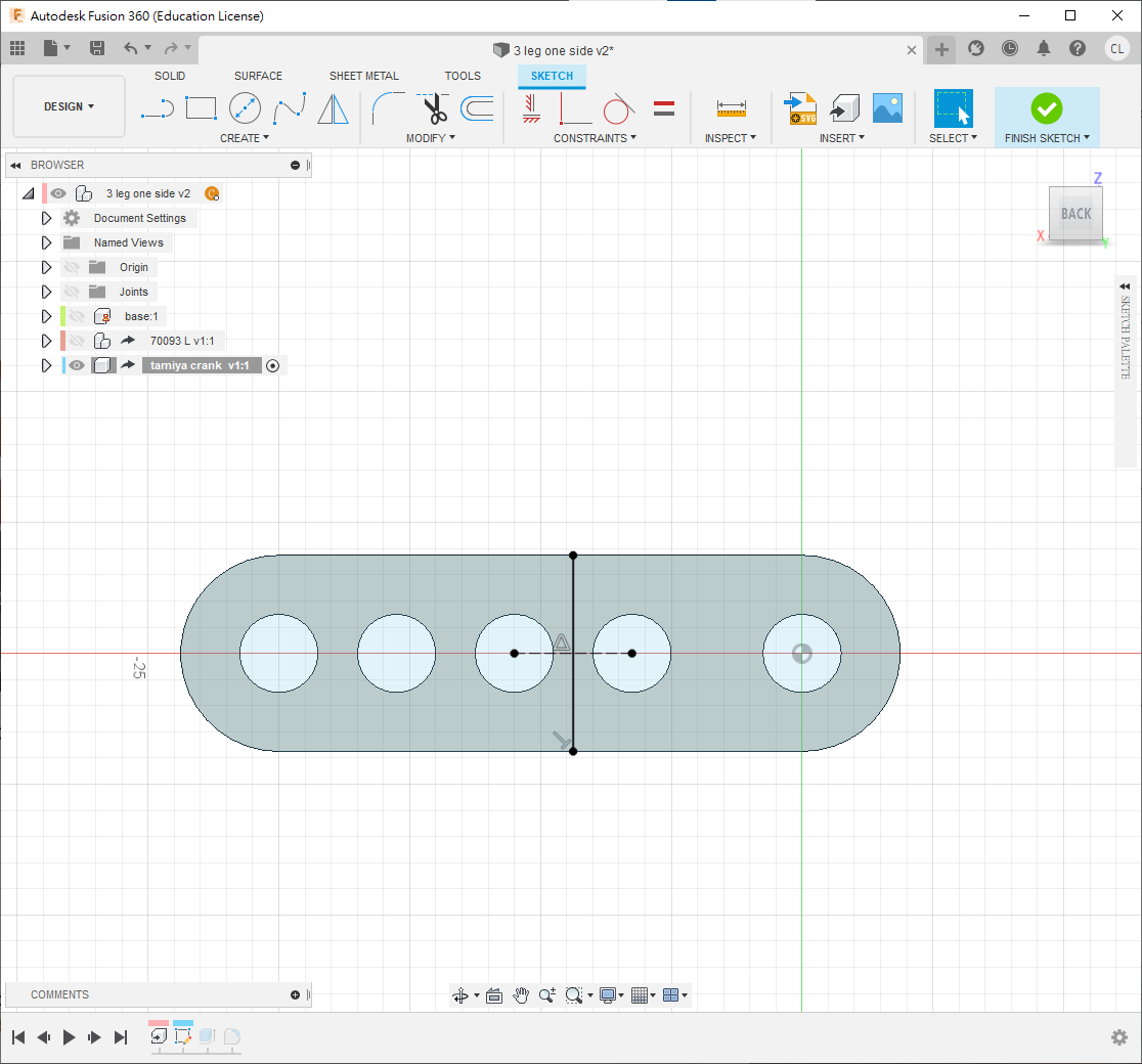
- Derive a Tamiya crank model.
- Sketch on its face using the dimensions shown.
- Press
Eto remove the excess material and apply a3 mmfillet. - Press
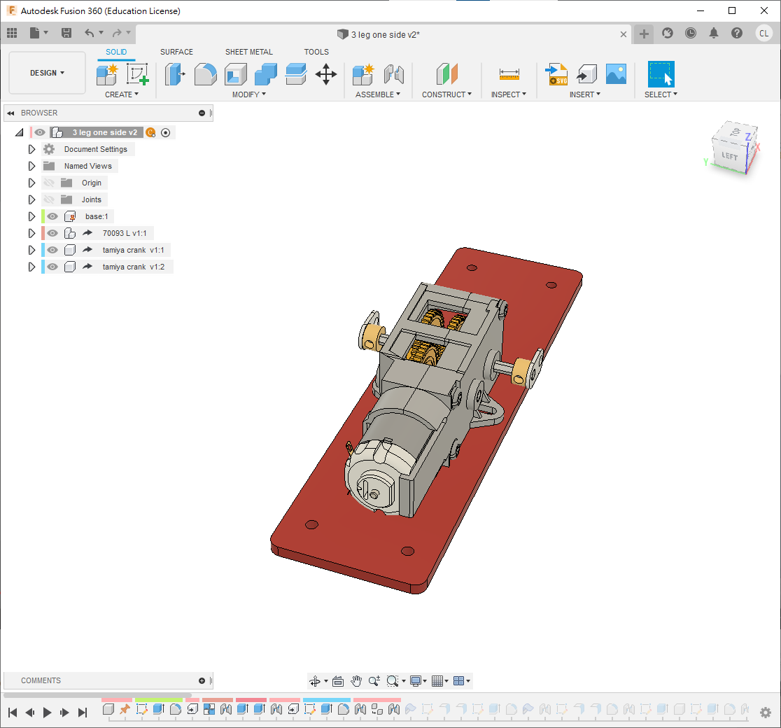
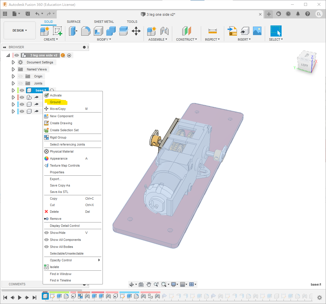
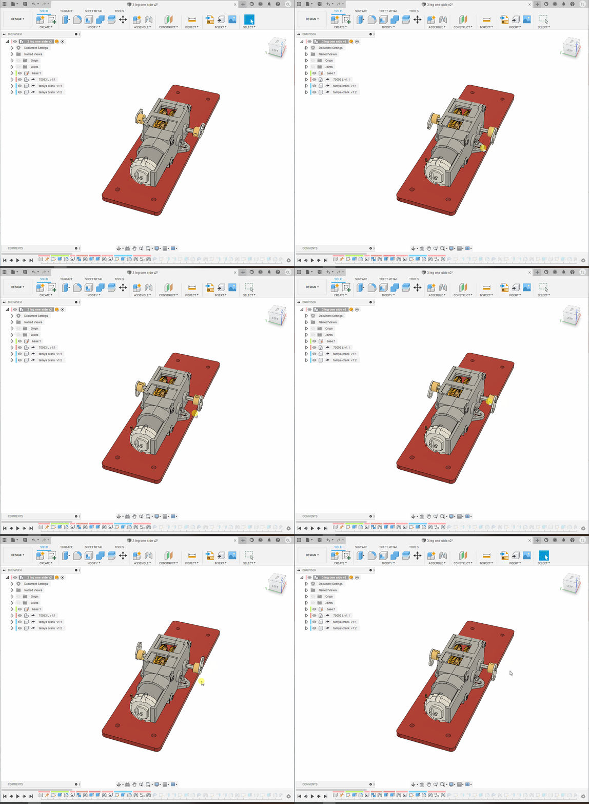
Jand rigid-joint the crank to the gearbox. At the top level, copy, paste and joint a second crank as shown. - Right-click
baseand chooseGround. - Test that both cranks rotate together.
Step 5: Short Support
- Create a sheet-metal component named
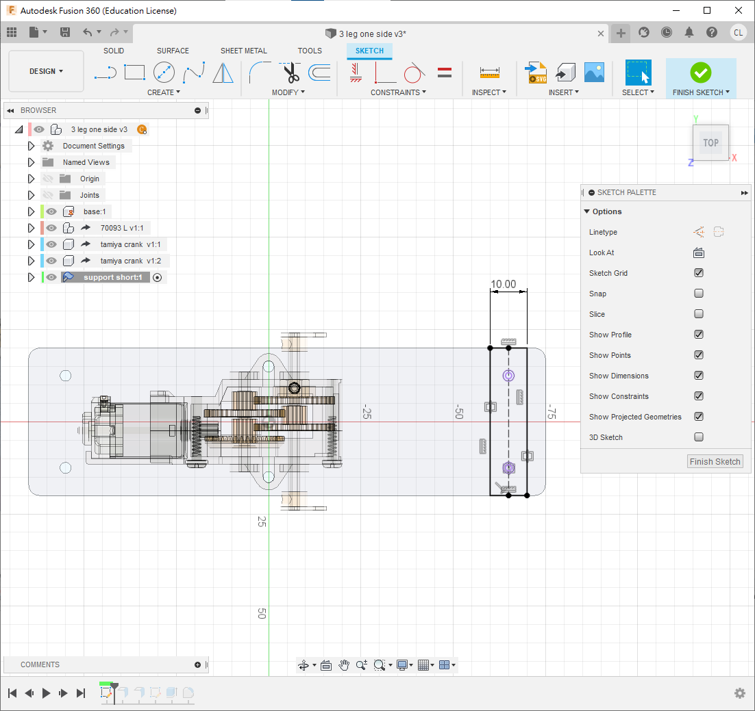
support short. - Sketch on the base. Press
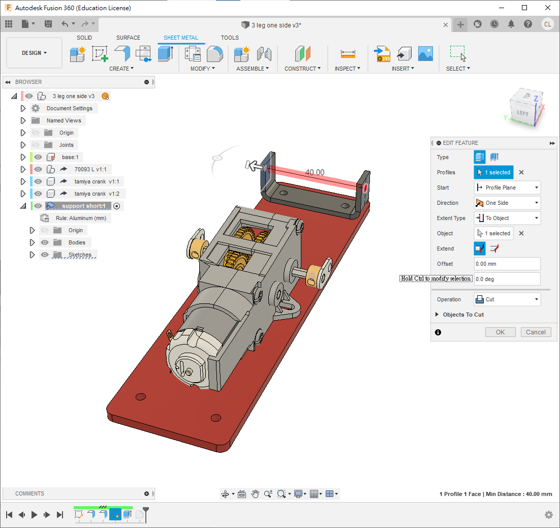
Pto project the rear gearbox holes, add a centreline and draw the 10 mm-wide rectangle shown. - In the Sheet Metal workspace, use
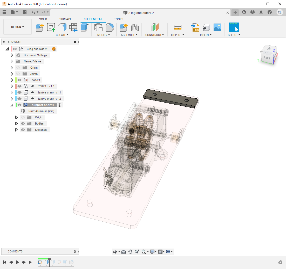
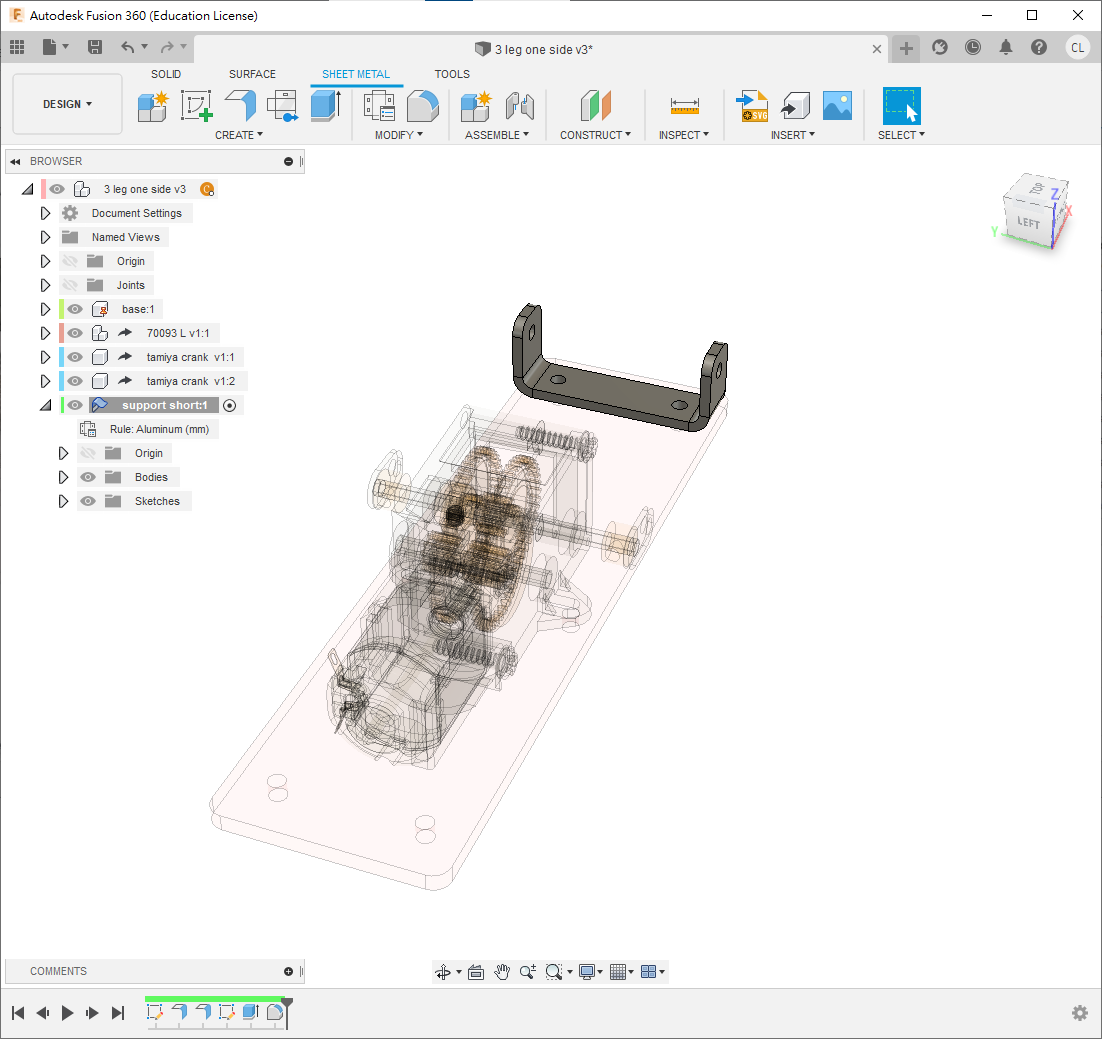
Flangeto create a 2 mm aluminium part. If necessary, change the material withSheet Metal Rules.
- Use
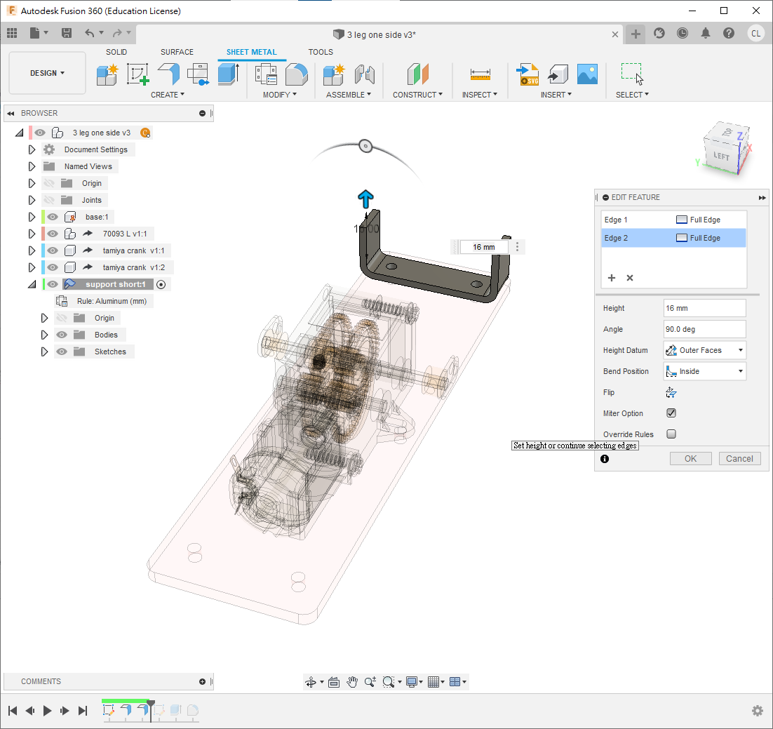
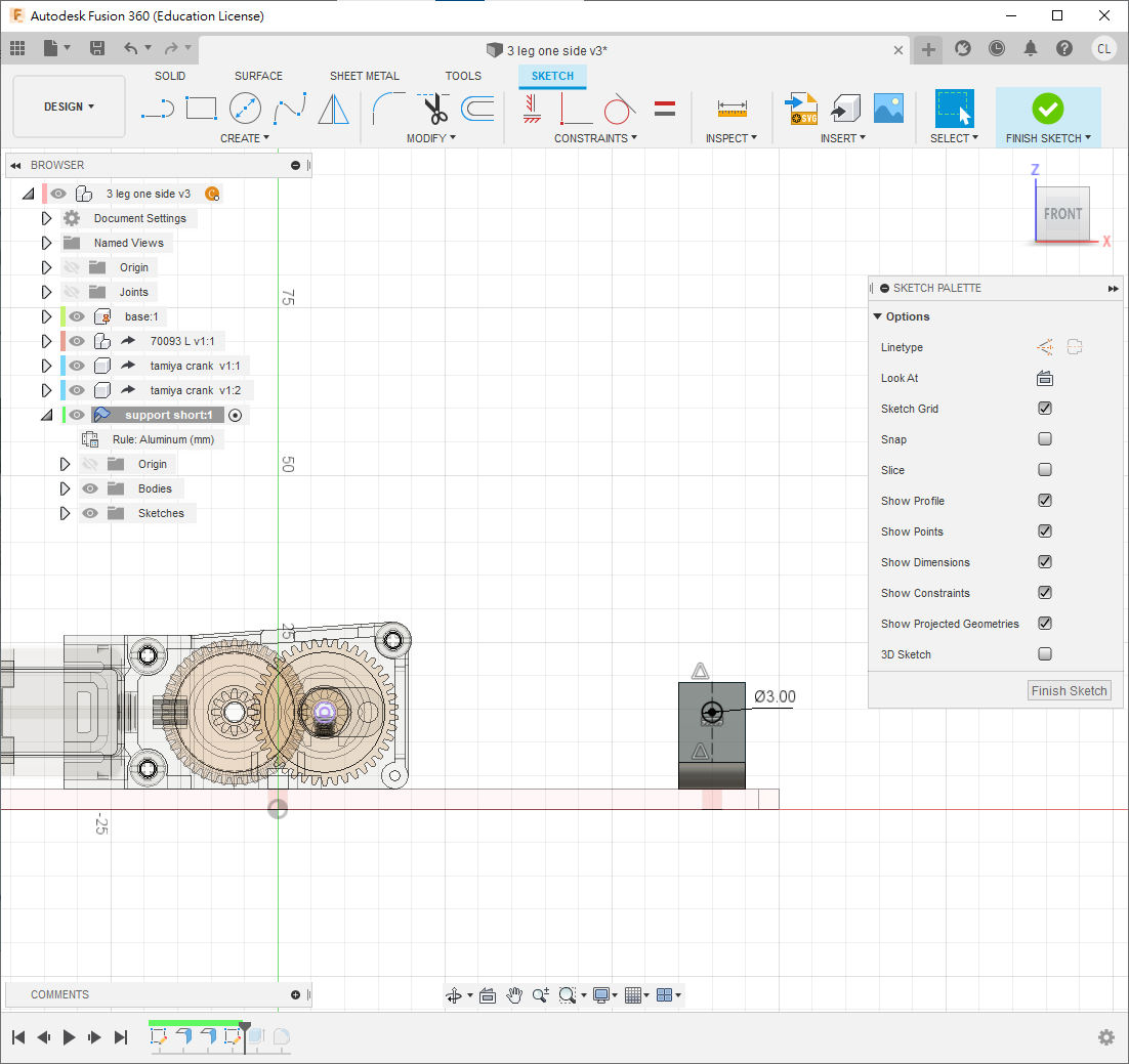
Flangeto bend both sides up by16 mm, withOuter FacesandInside Bend Position. - Sketch a 3 mm hole on the raised side, level with the gearbox shaft.
- Cut through both sides and fillet the four corners by 2 or 3 mm.
Step 6: Long Support
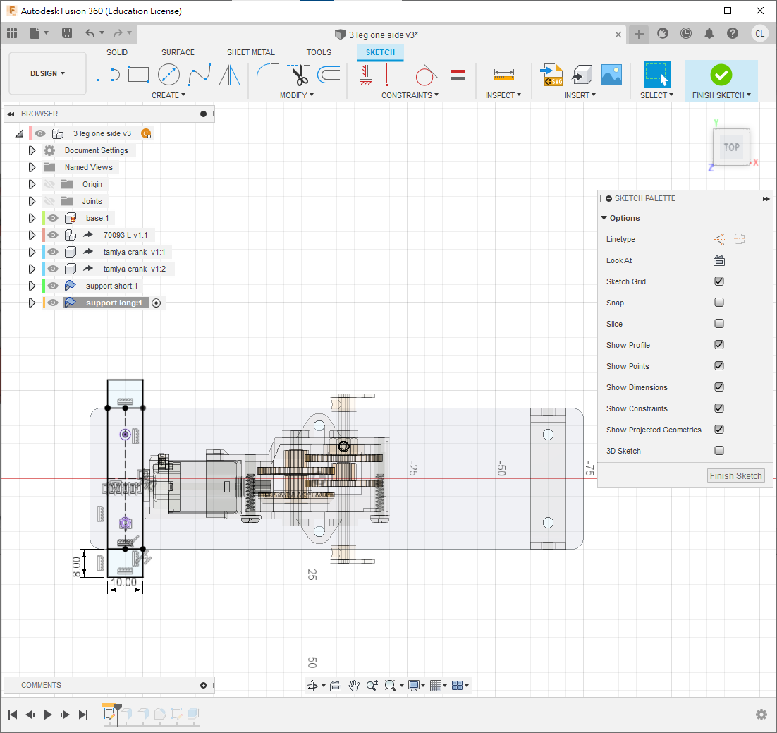
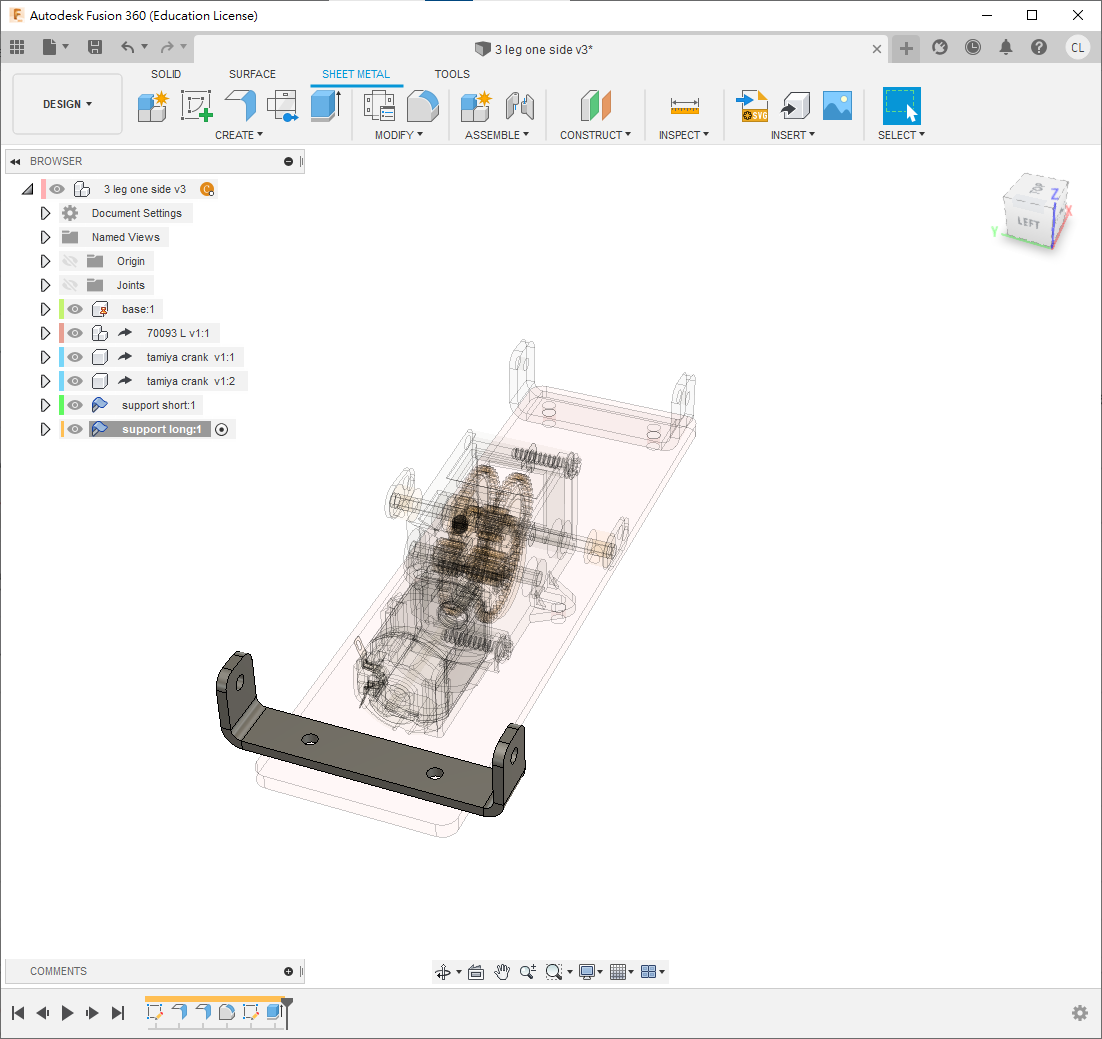
Create another sheet-metal component named support long. Repeat Step 5, but make the initial rectangle 8 mm longer while retaining its 10 mm width. Use 2 mm aluminium, 16 mm side flanges, 3 mm shaft-height holes and 3 mm corner fillets.
Step 7: Leg
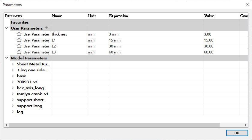
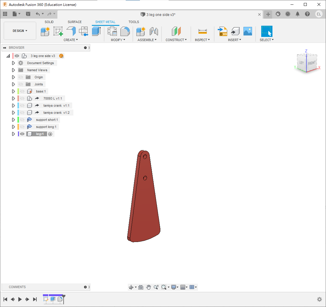
- Open
Change Parametersand add the variables shown. - At the top level, create a standard component named
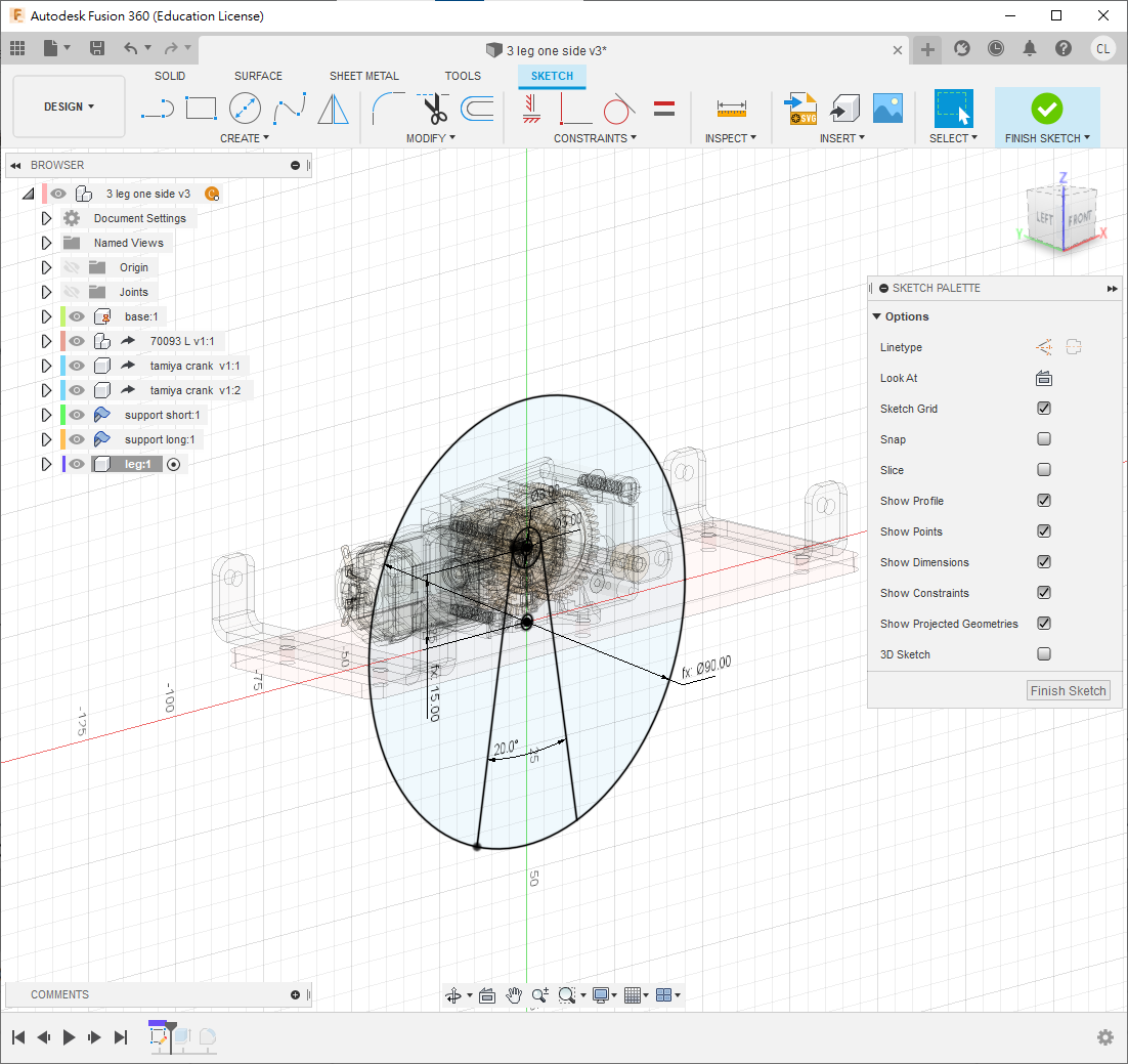
leg. - Hide other components and sketch on the XZ plane, or the robot's side plane.
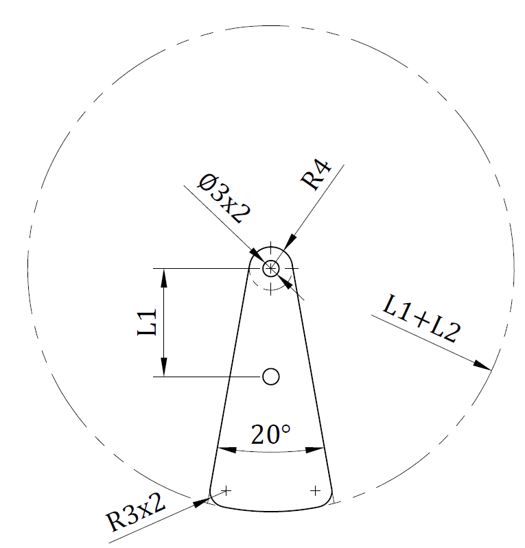
- Draw the profile to the dimensions shown.
- Extrude by
thicknessand apply3 mmfillets to the corners.
Step 8: First Linkage
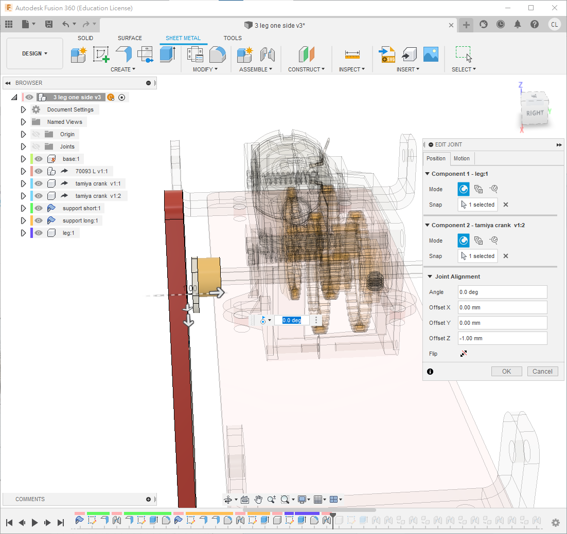
Reactivate the top level and show the hidden components. Press J and attach the leg to the crank's second hole with a Revolute joint and Z offset = 1 mm.
This model deliberately avoids putting all legs and links inside one parent component: both sides must move symmetrically, the joints will be retained when the half-model is derived, and the repeated joints provide useful practice.
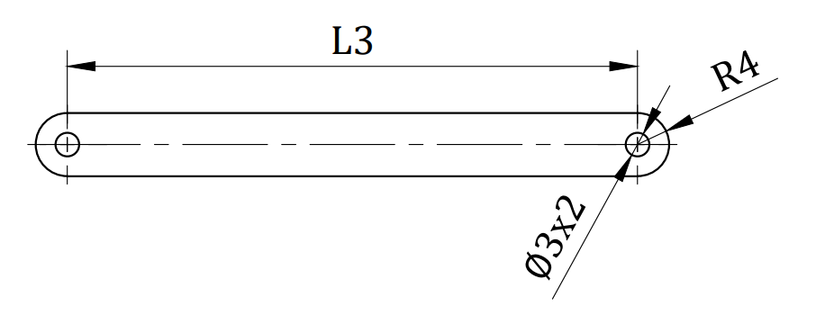
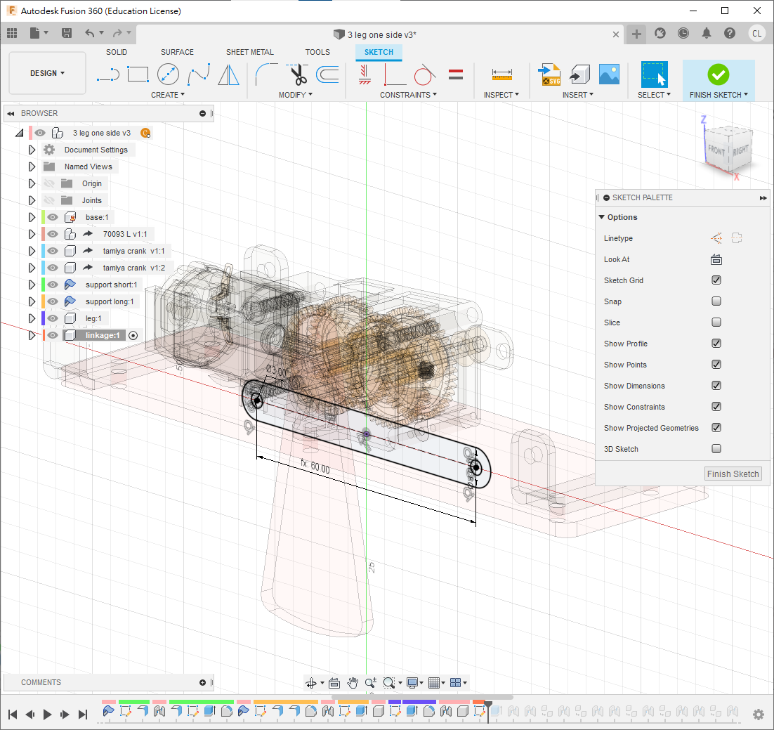
Create a top-level component, sketch the linkage on the side plane to the dimensions shown, and extrude it by thickness.
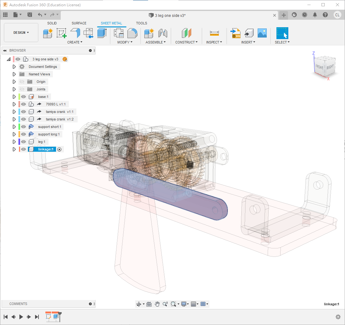
- Attach one end of the linkage behind the leg with a Revolute joint and
1 mmspacing. - Attach the other end to the support hole with a Cylindrical joint; no offset is required.
💡TIP
For a four-bar linkage, use two Revolute joints and one Cylindrical joint among the three connections. Their order can vary. This avoids having to calculate offsets from every part thickness.
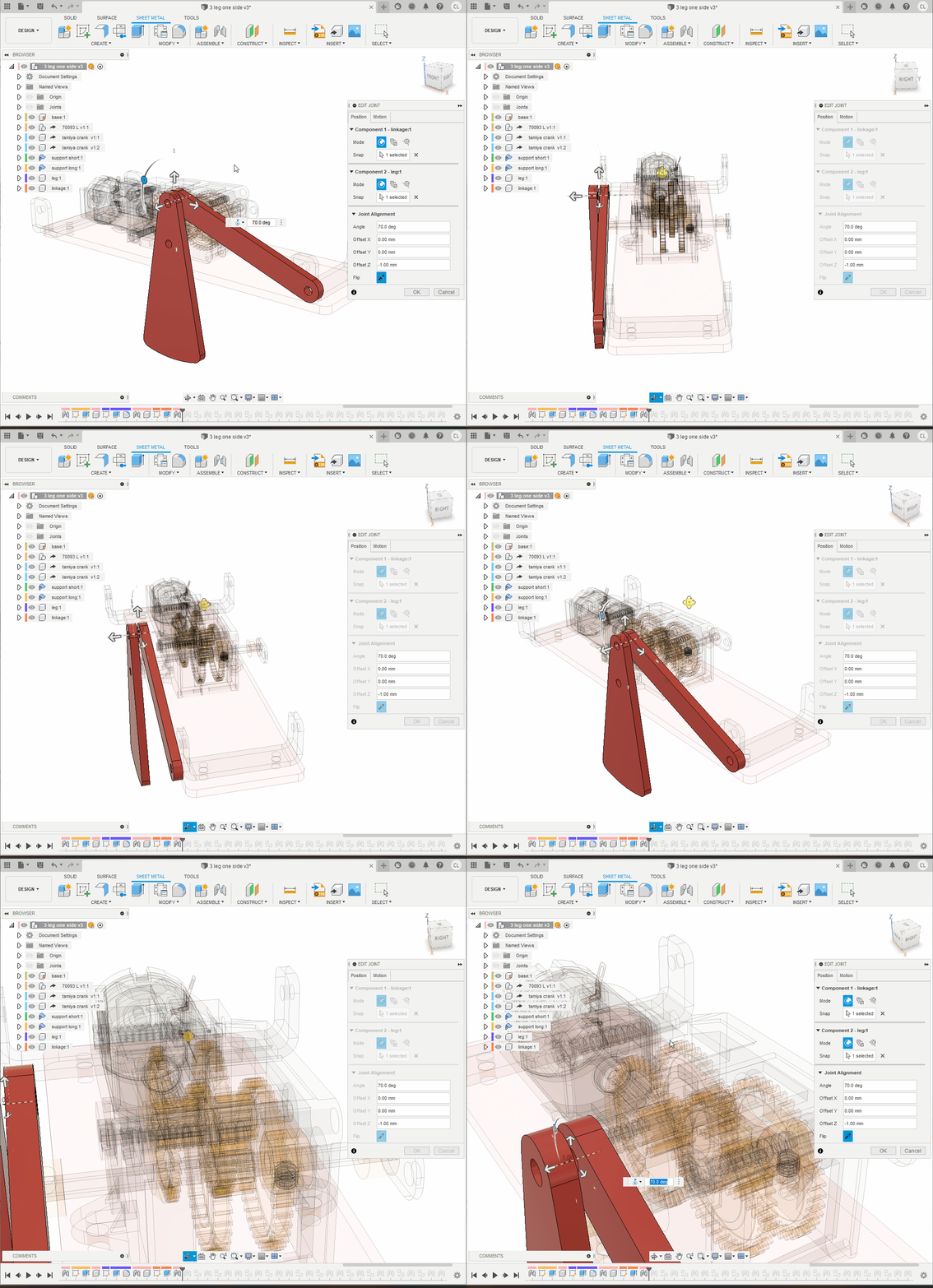
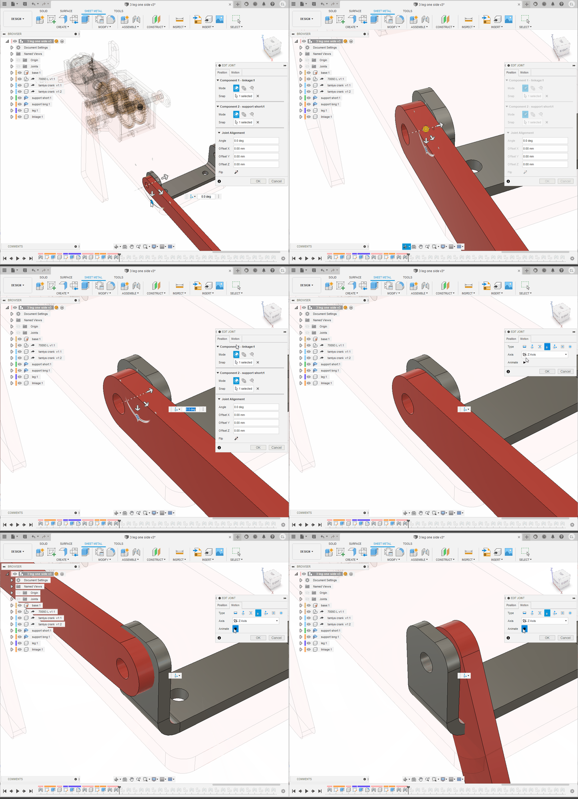
Step 9: Second Leg
At the top level, copy the leg and linkage and assemble the second leg using the same two-Revolute-plus-one-Cylindrical arrangement. Keep 1 mm between each leg and linkage. Rotate the mechanism to test it. If it folds into an impossible over-centre position, restrict it with Joint Limits.
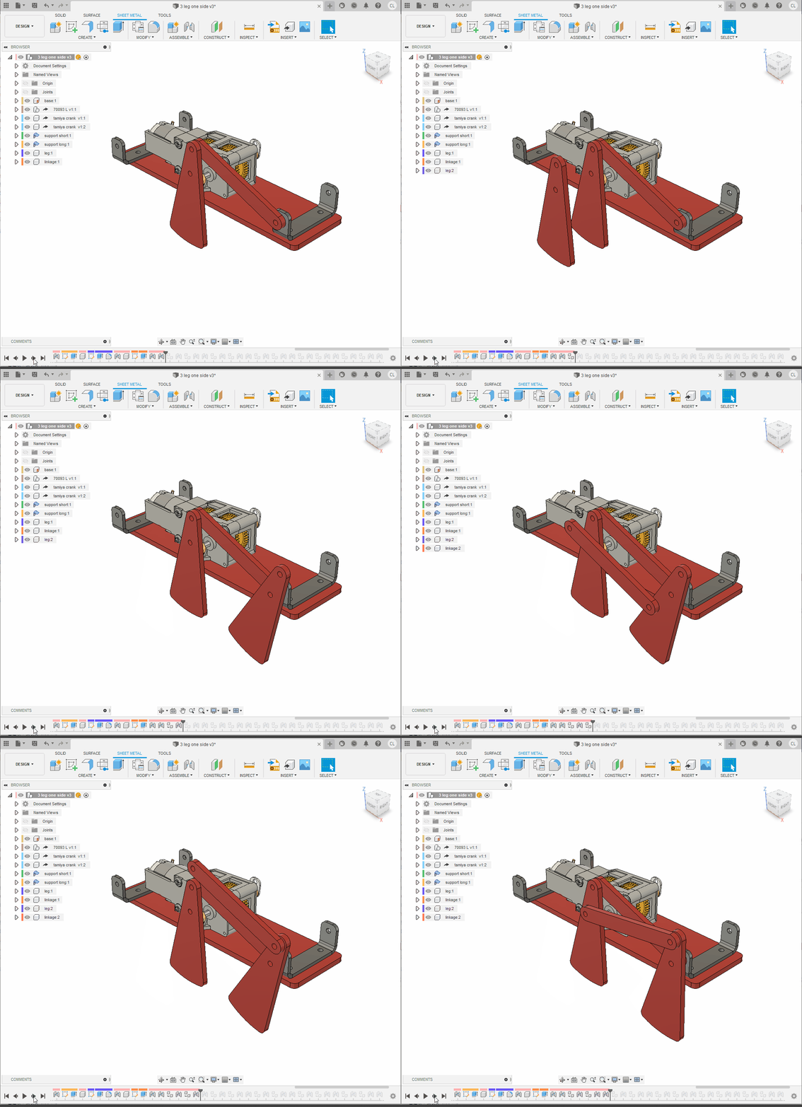
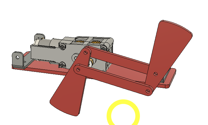
Correcting an over-centre linkage
The video demonstrates the process. Exact angle values vary with joint orientation, so display the joint and observe its natural range before entering limits.
Step 10: Third Leg
Repeat the same process for the remaining linkage.
💡TIP
Remember: each four-bar assembly uses two Revolute joints and one Cylindrical joint.
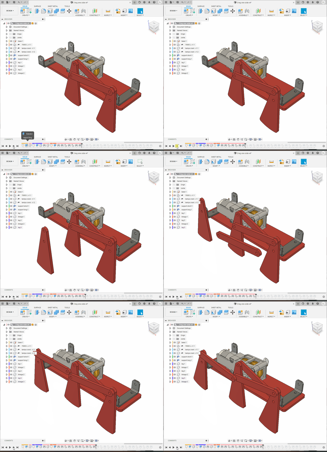
Step 11: Other Side of the Half-Robot
Build and joint the corresponding legs on the other side of this half-model. This repetition builds familiarity and ensures symmetry. If a linkage goes over centre, step back in the timeline and adjust its starting angle or use Joint Limits. Save the completed half.
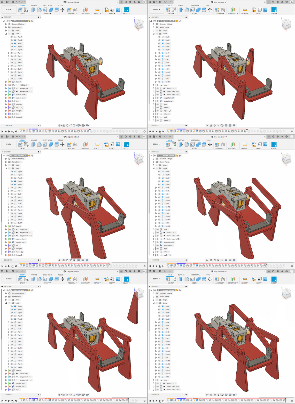
Step 12: Complete Robot
- Create a new design and use
Insert Deriveto insert the half-robot. - Ground its
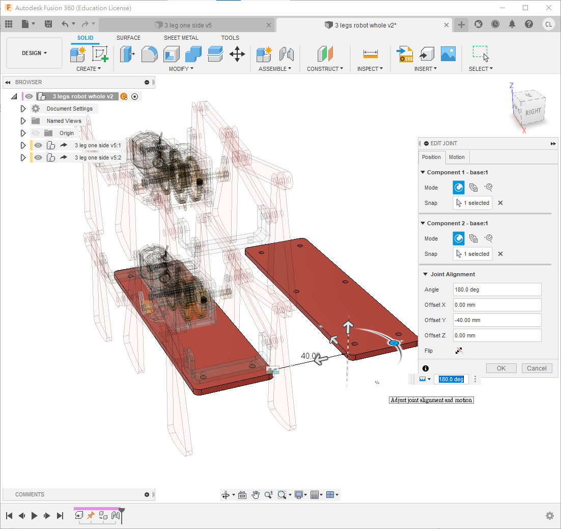
base; all joints should remain intact. - Copy the entire derived component and rigid-joint the two base plates 40 mm apart horizontally.
ℹ️INFO
A physical robot would need additional plastic or aluminium plates joining the two halves.
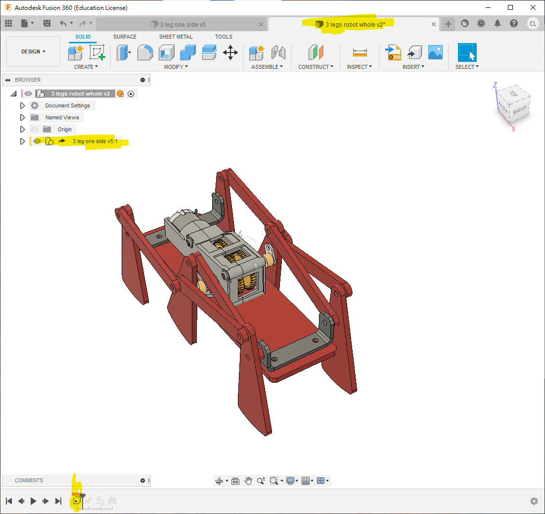
Complete!
Translation notice: This English page was generated automatically by AI and has not yet been reviewed by a human. It will be checked and revised page by page when time permits.