2D Constraints
ℹ️INFO
Fusion 360 is feature-based and follows the logic of mathematical geometry. Coordinate-based applications such as AutoCAD and Rhino may record only the endpoints of a tangent line; if the circles move or change size, that line no longer remains tangent. A parametric modeller records the geometric Tangent relationship itself, so the line remains tangent when the circles change.
Constraint Tools
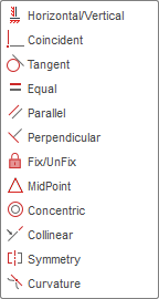
Horizontal/Vertical
Makes a selected line horizontal or vertical, or aligns two selected points horizontally or vertically.
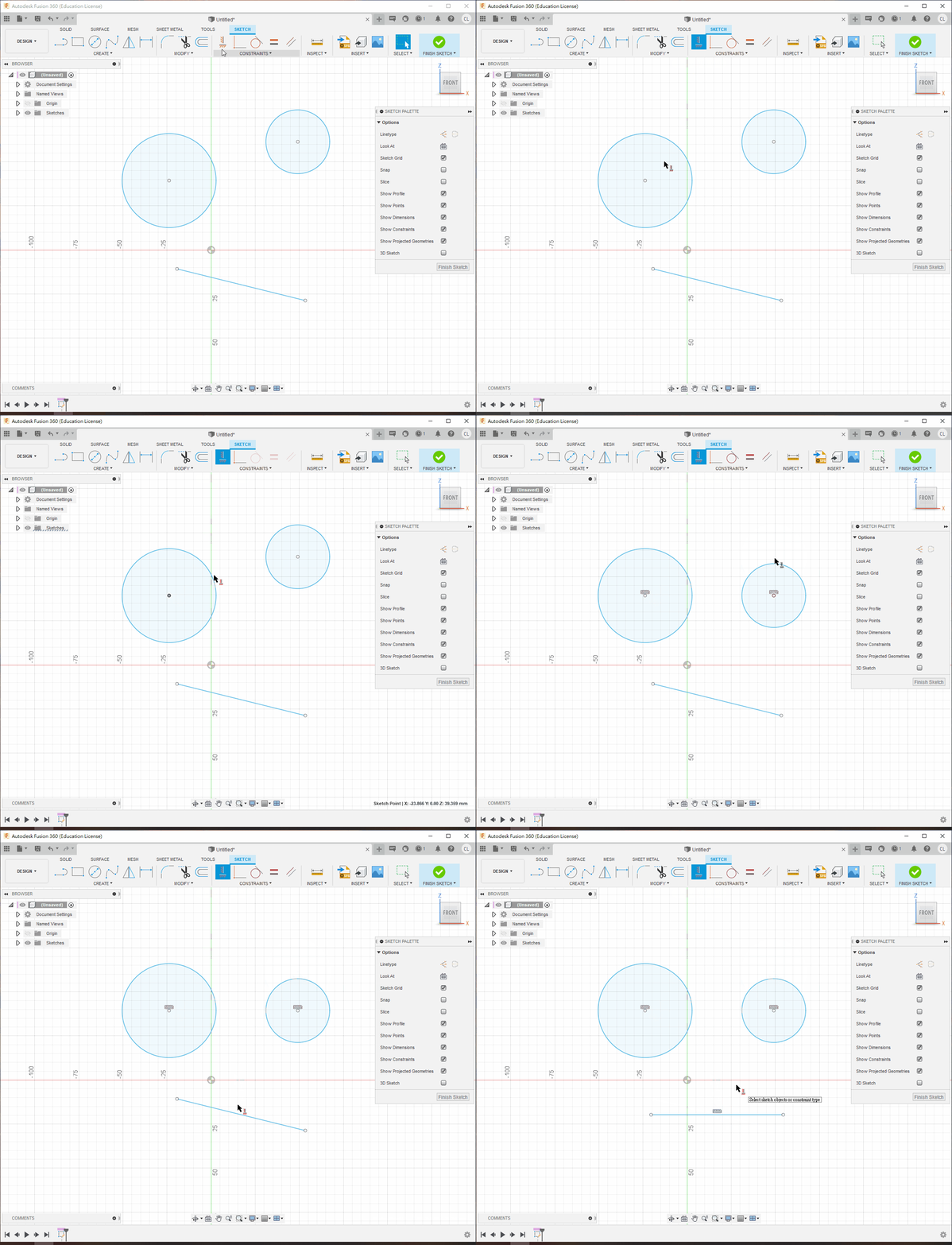
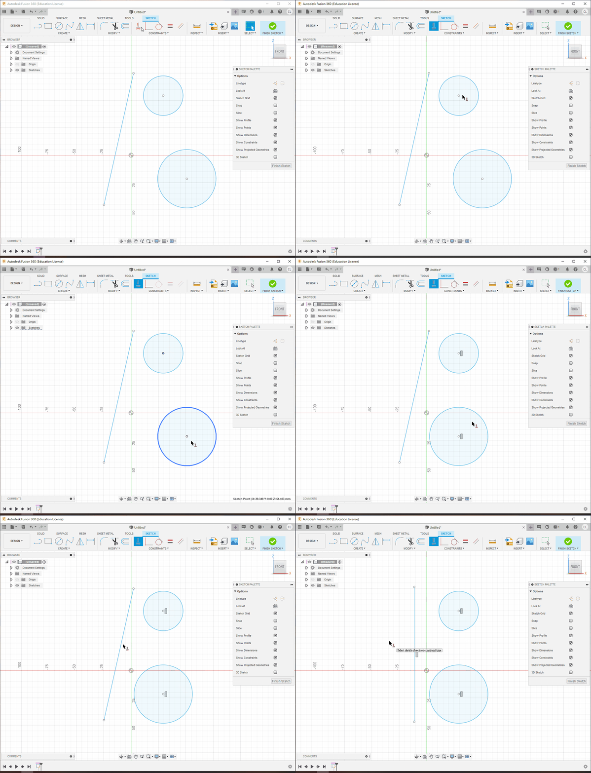
Coincident
Constrains two points to the same location, or constrains a point onto a curve.
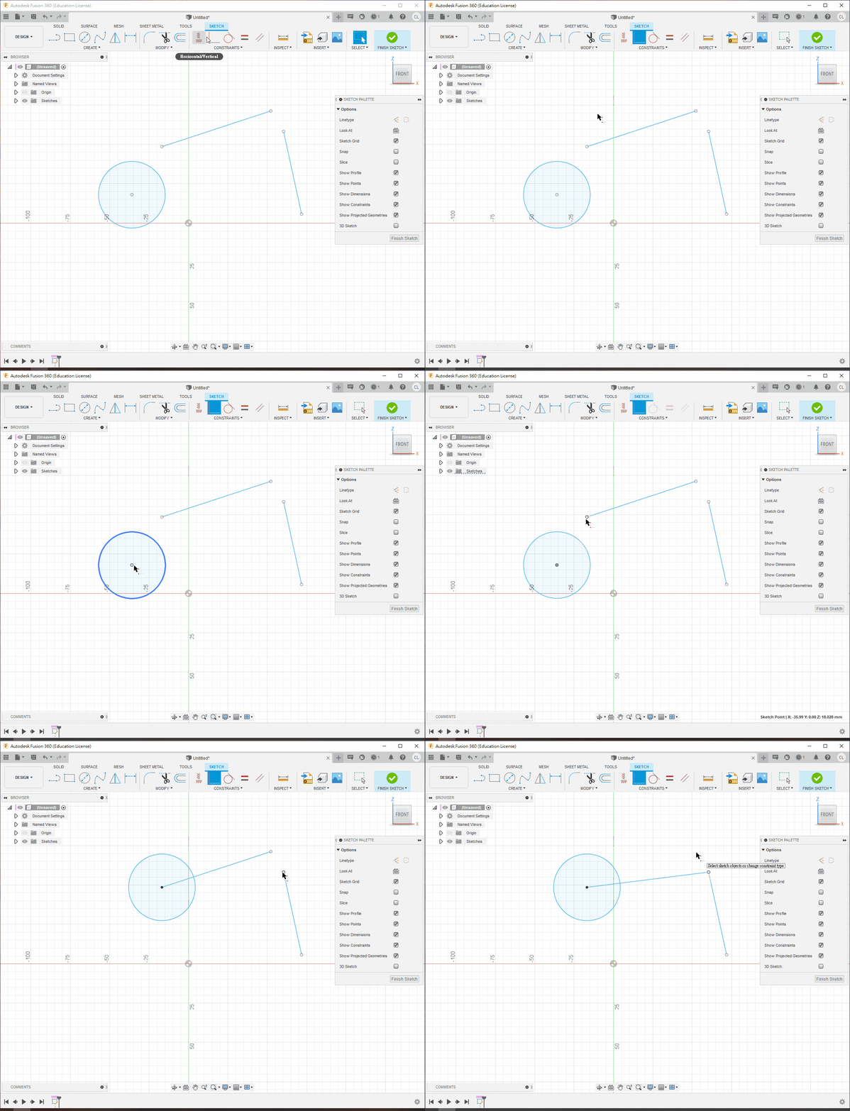
Tangent
Makes a line or curve tangent to a circle or arc.
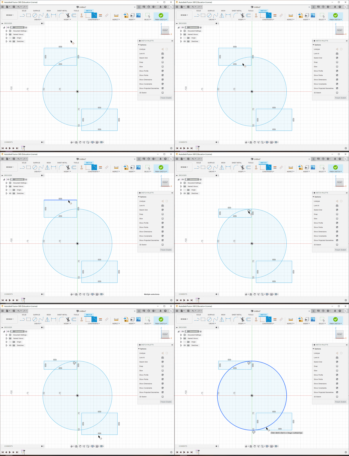
Equal
Makes selected lines equal in length, or circles and arcs equal in radius. It is particularly useful for repeated screw holes: changing one diameter from M3 to M2 updates every hole linked by the constraint.
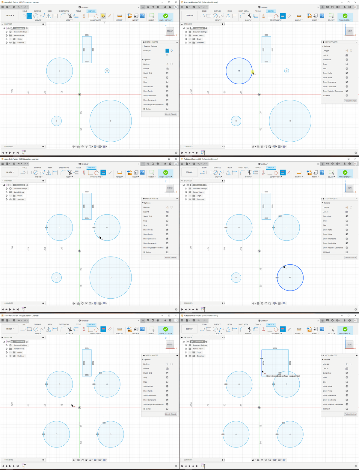
Parallel
Makes selected lines parallel.
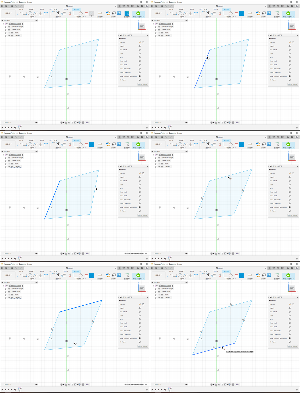
Perpendicular
Makes selected lines perpendicular.
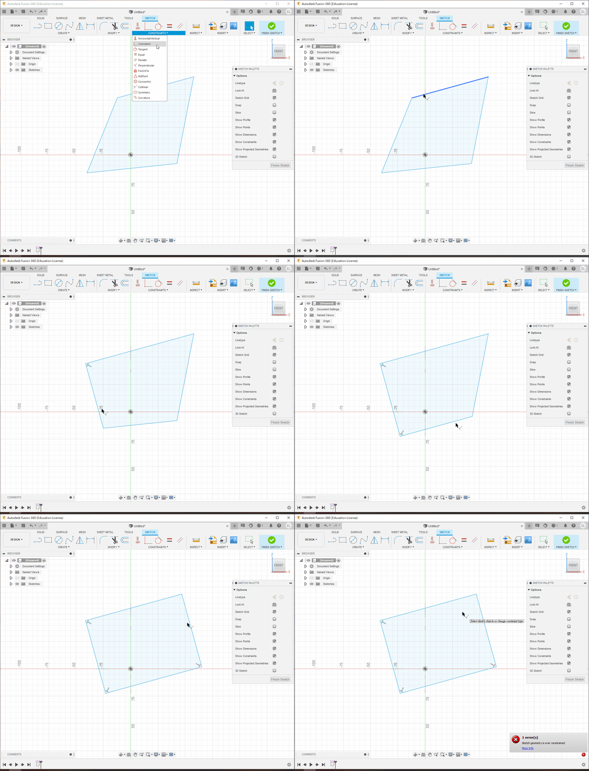
Fix/Unfix
Locks or unlocks a point, line or curve at its current position or size.
⚠️WARNING
Avoid this constraint whenever a meaningful geometric or dimensional constraint can be used instead.
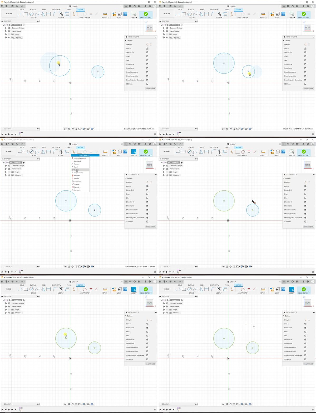
Midpoint
Constrains a point to the midpoint of a line, or aligns the midpoints of two or more lines.
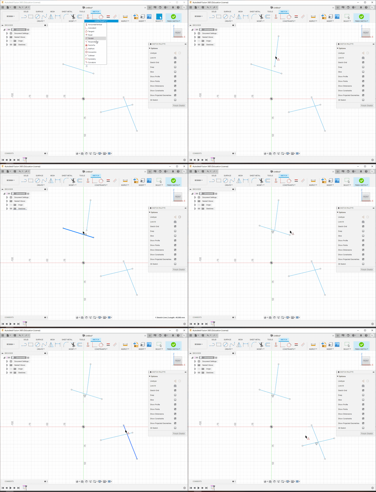
Concentric
Places the centres of two circles, ellipses or arcs at the same point.

Collinear
Places two or more line segments on the same infinite line.
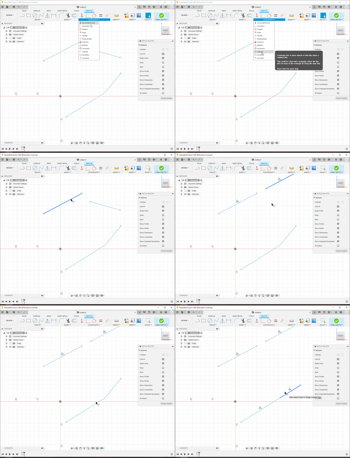
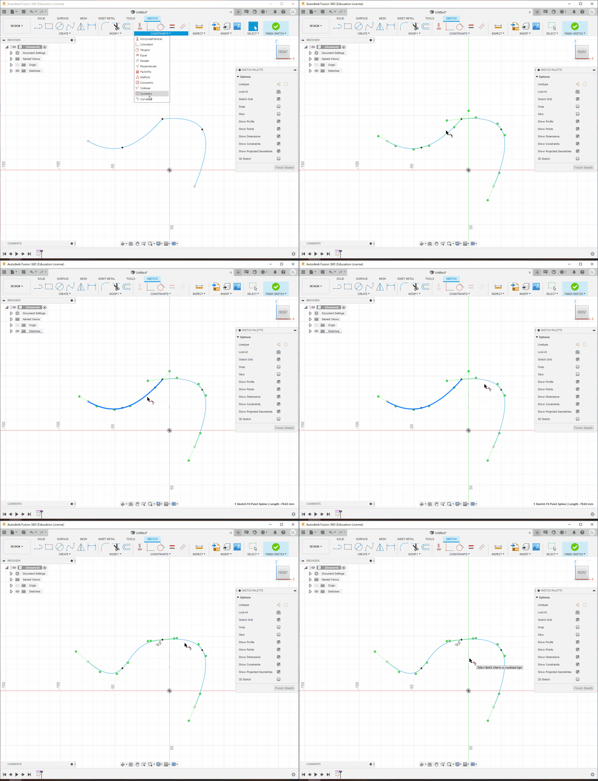
Symmetry
Makes selected geometry symmetrical about a selected centreline. Unlike Mirror, this constraint can be applied after both sides have already been drawn.
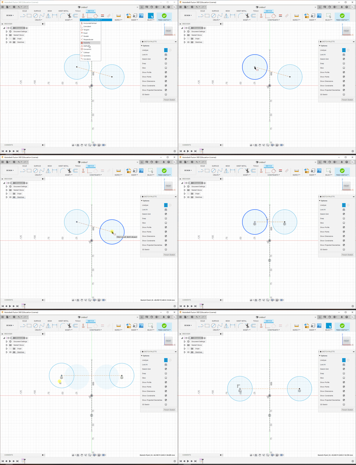
Curvature
Creates smooth curvature continuity where a spline meets another curve, line or arc. It is intended mainly for Bézier or spline curves.
Exercises
Exercise 1
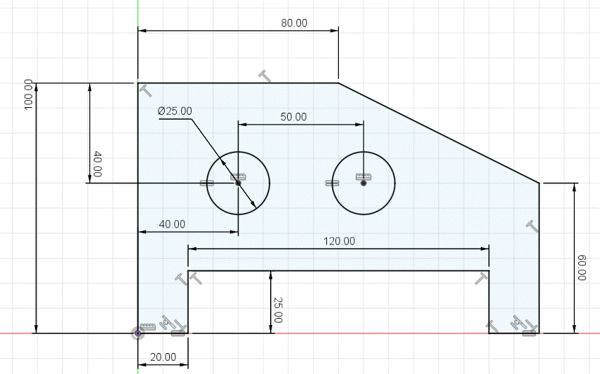
Press
Land sketch the approximate outline.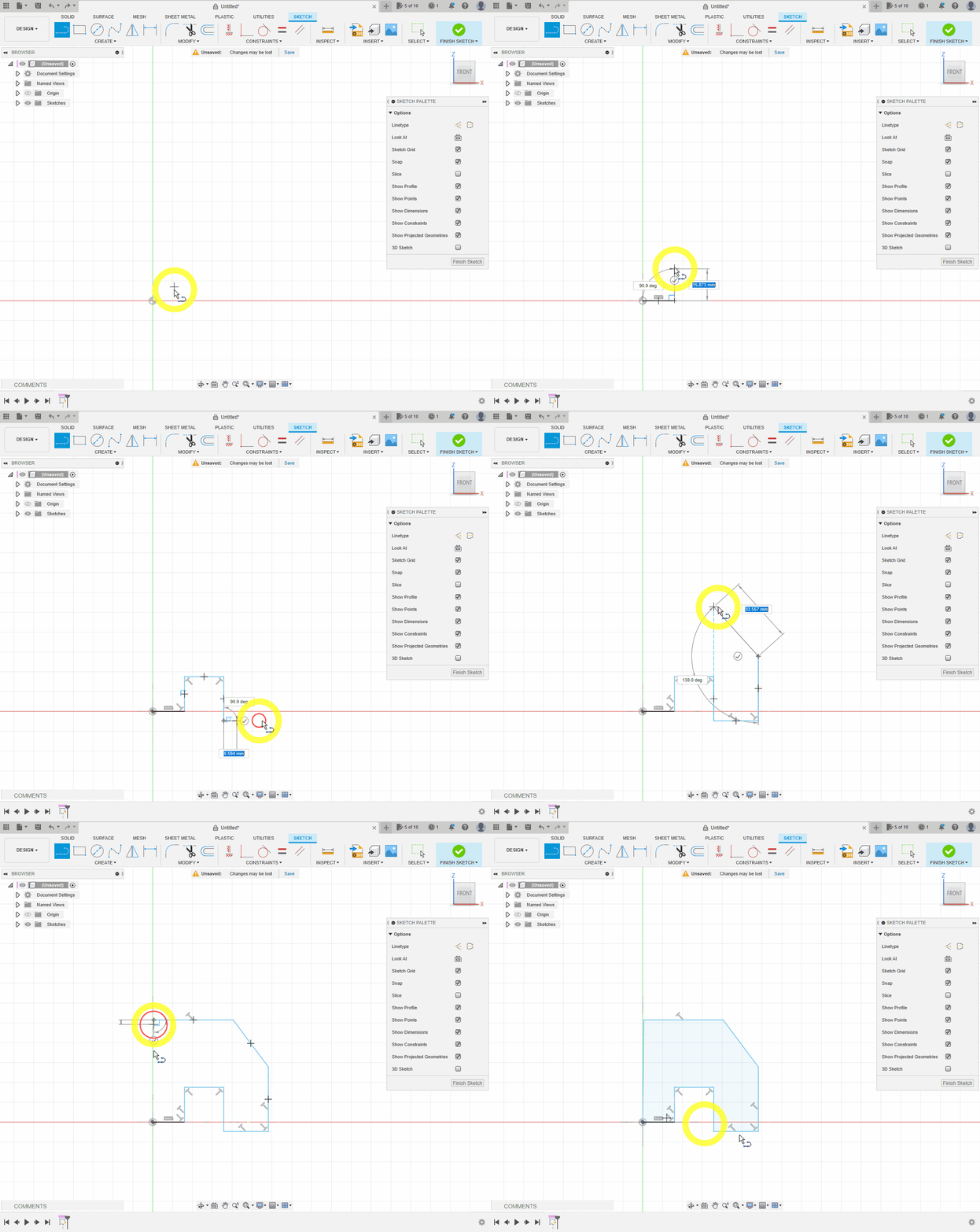
Use Horizontal/Vertical or Perpendicular so that all relevant lines are horizontal or vertical.
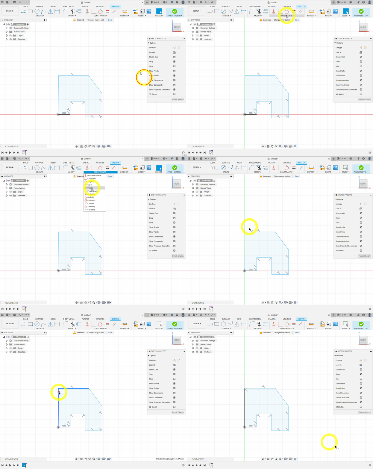
Use Collinear to align the two feet.
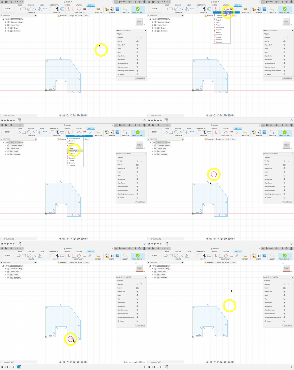
Use Equal to make the feet the same width.
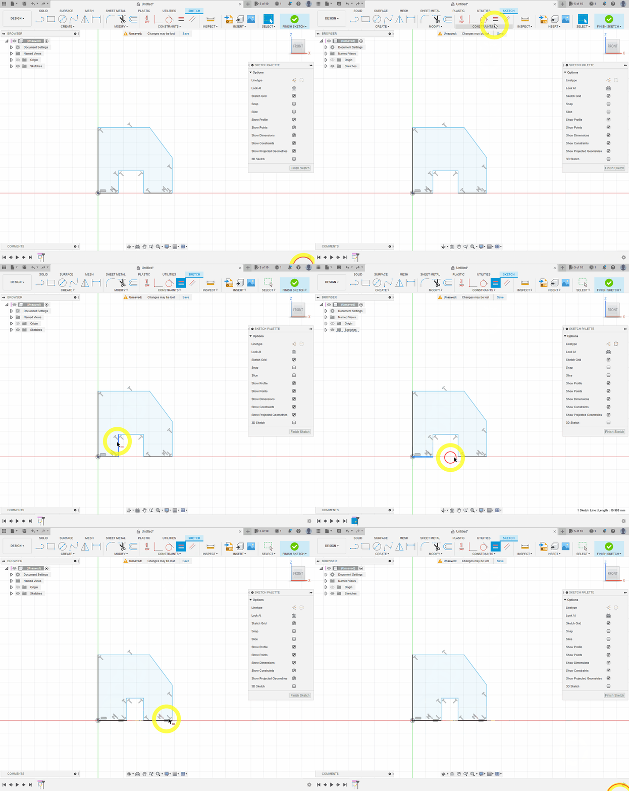
Press
D; set the lower-left horizontal line to20and the short vertical line to25.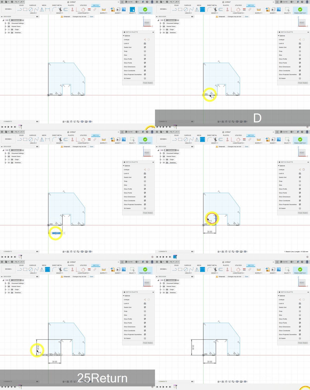
Add the remaining dimensions shown and confirm that every line turns black.
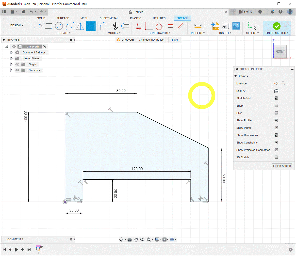
Press
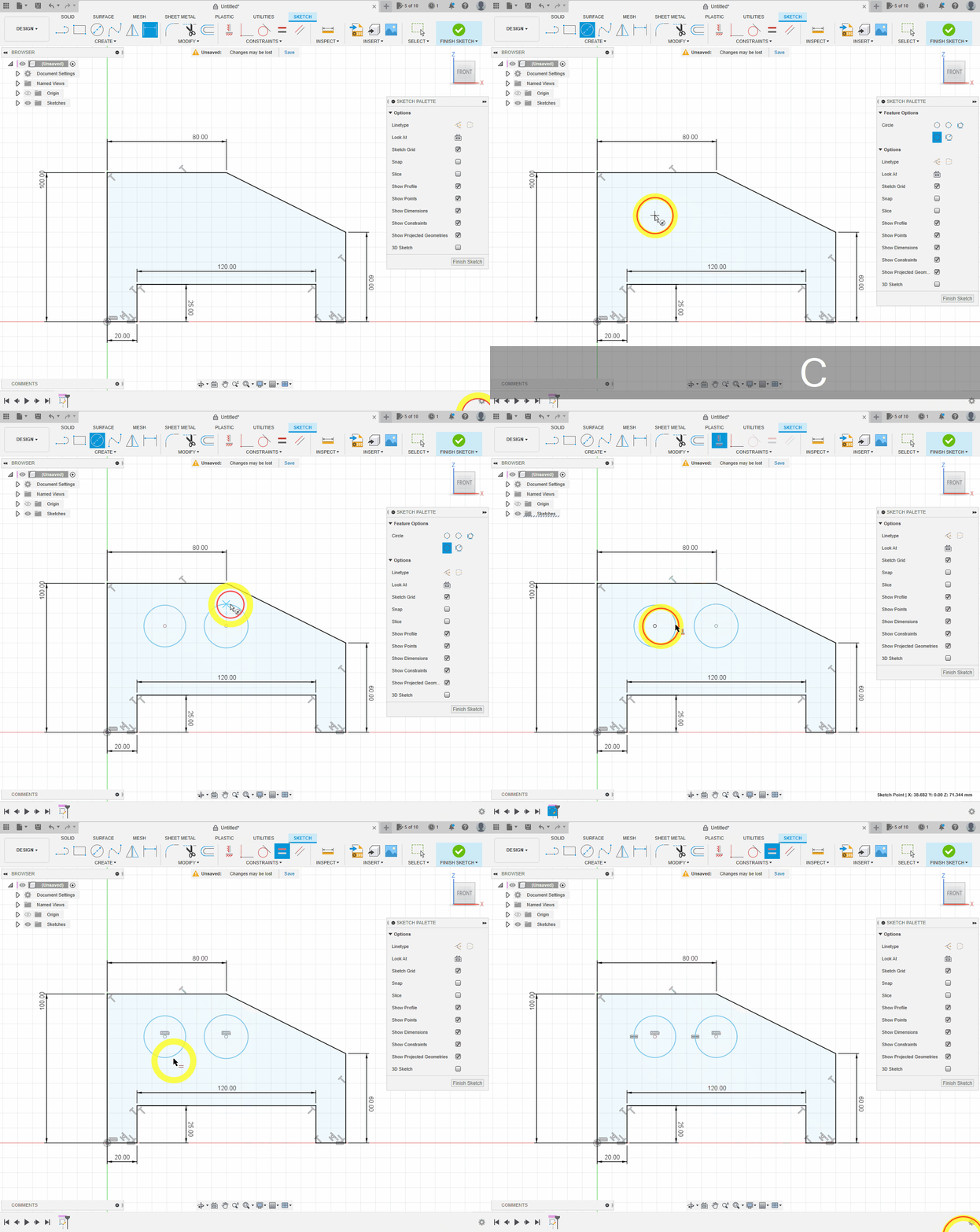
Cand draw two circles. Align their centres horizontally and apply Equal to their diameters.💡 Fusion 360 does not require extra construction lines simply to position dimensions.
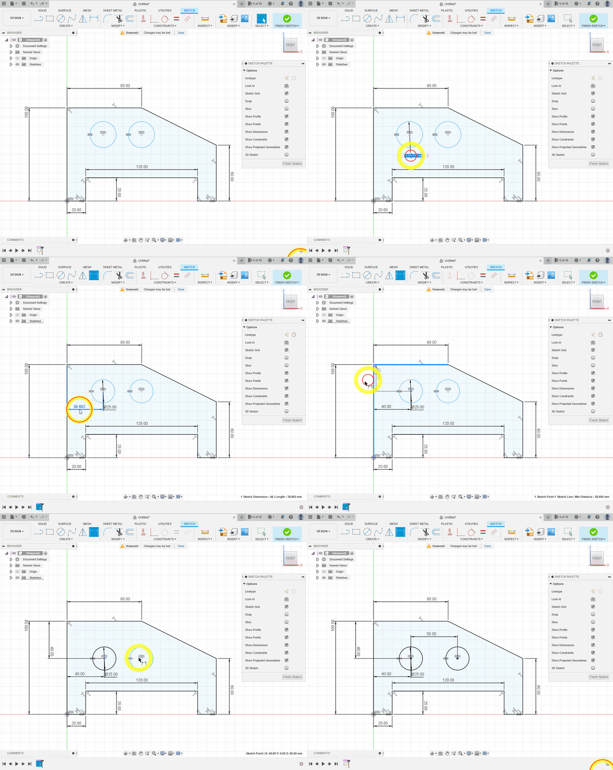
Dimension the size and position of the circles.
Press
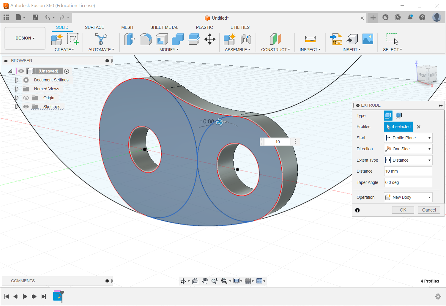
Sand search forExtrude, or pressEorQ, then extrude the profile by10 mm.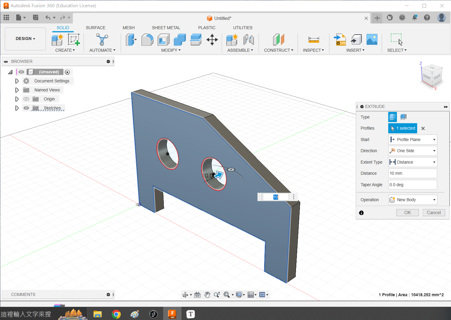
Exercise 2
- Press
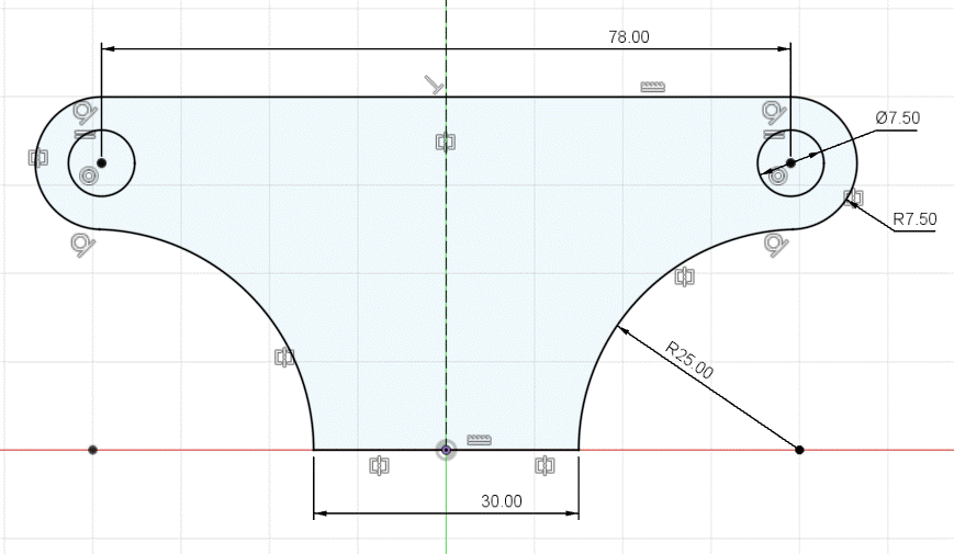
Land useSto find3-Point Arc; sketch the approximate shape. Right-click to repeat the previous command.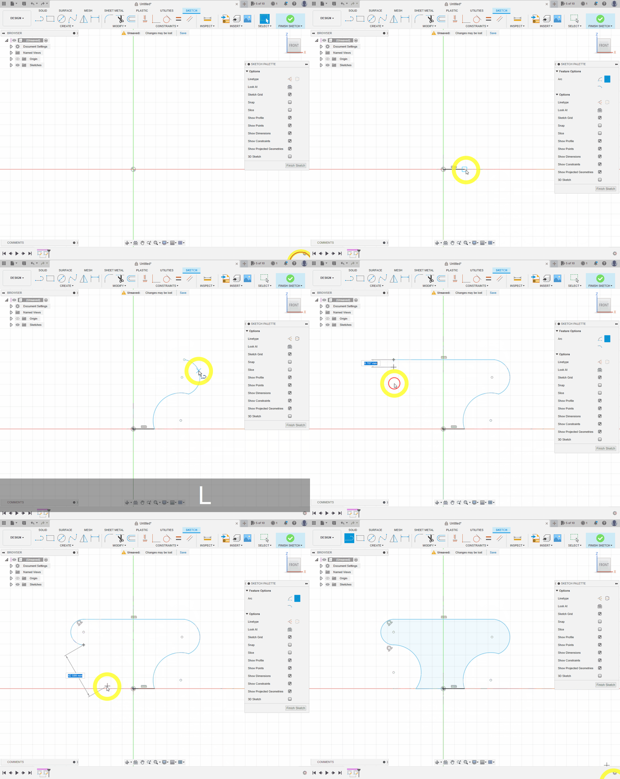
- Draw a centreline with
L, then pressXto make it construction geometry. - Apply Tangent wherever the arcs and lines meet.
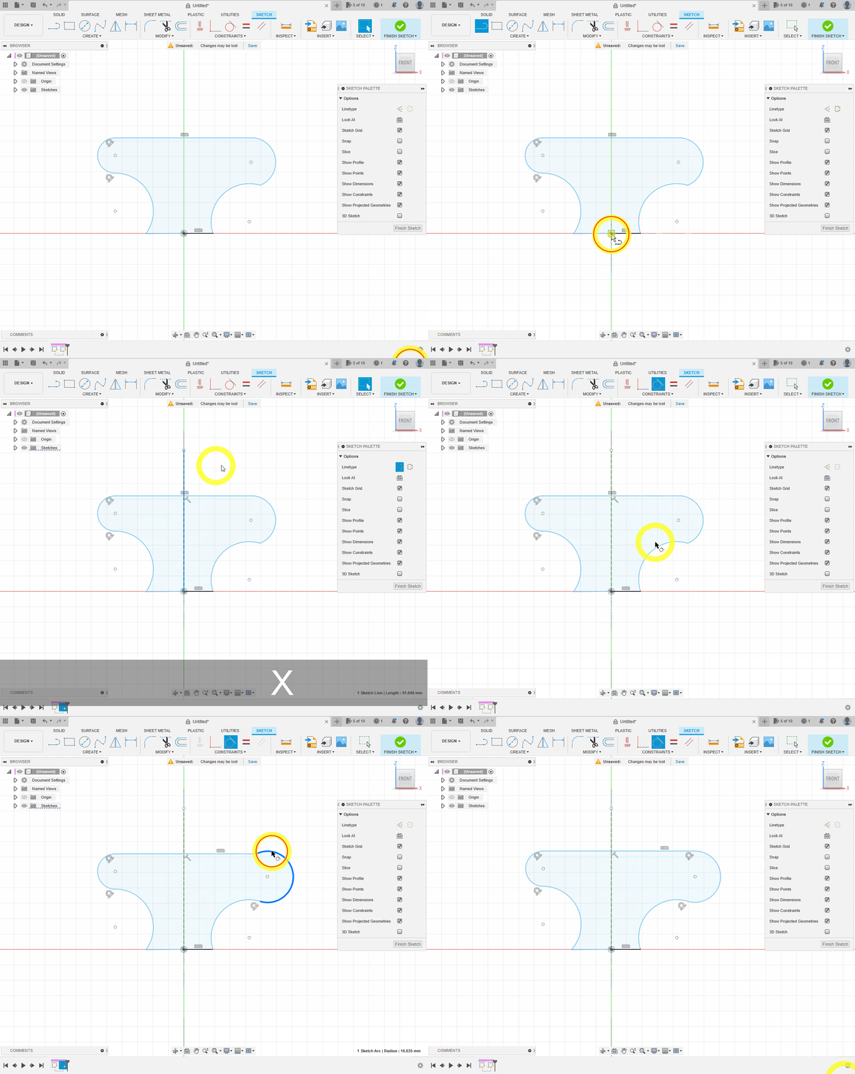
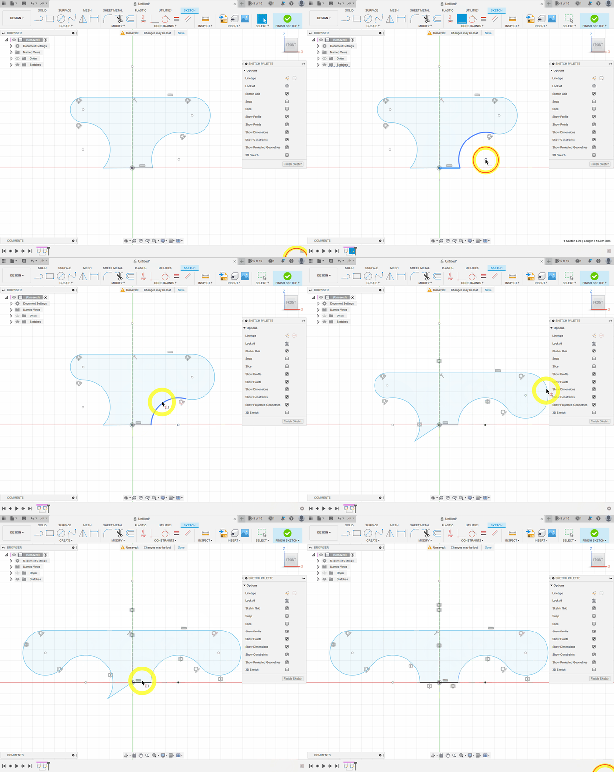
- Apply Coincident between the lower-right arc centre and the horizontal line.
- Select the matching objects and then the centreline with Symmetry to make the entire profile symmetrical.
- Draw two circles with
C. Make them concentric with the two outer lobes and Equal to one another.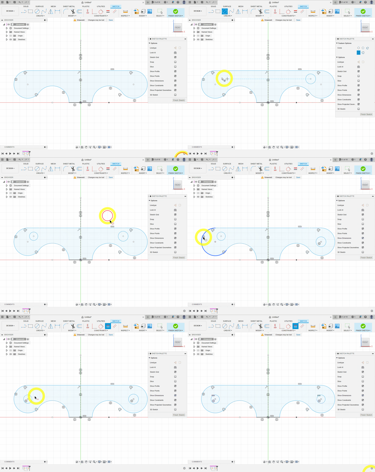
- Press
D, add all dimensions and ensure every line is black. - Extrude by
10 mm.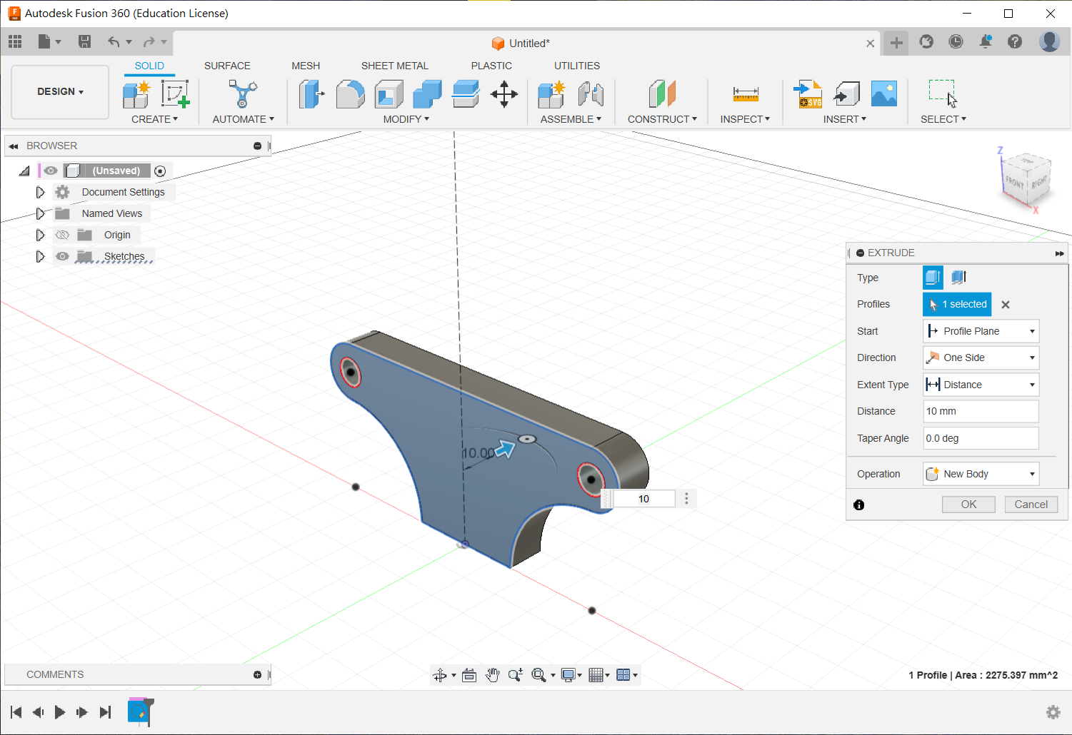
Exercise 3
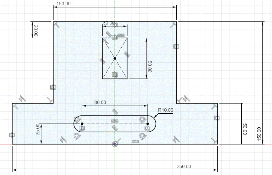
- The part is symmetrical. Starting at the origin, sketch its approximate outer profile.
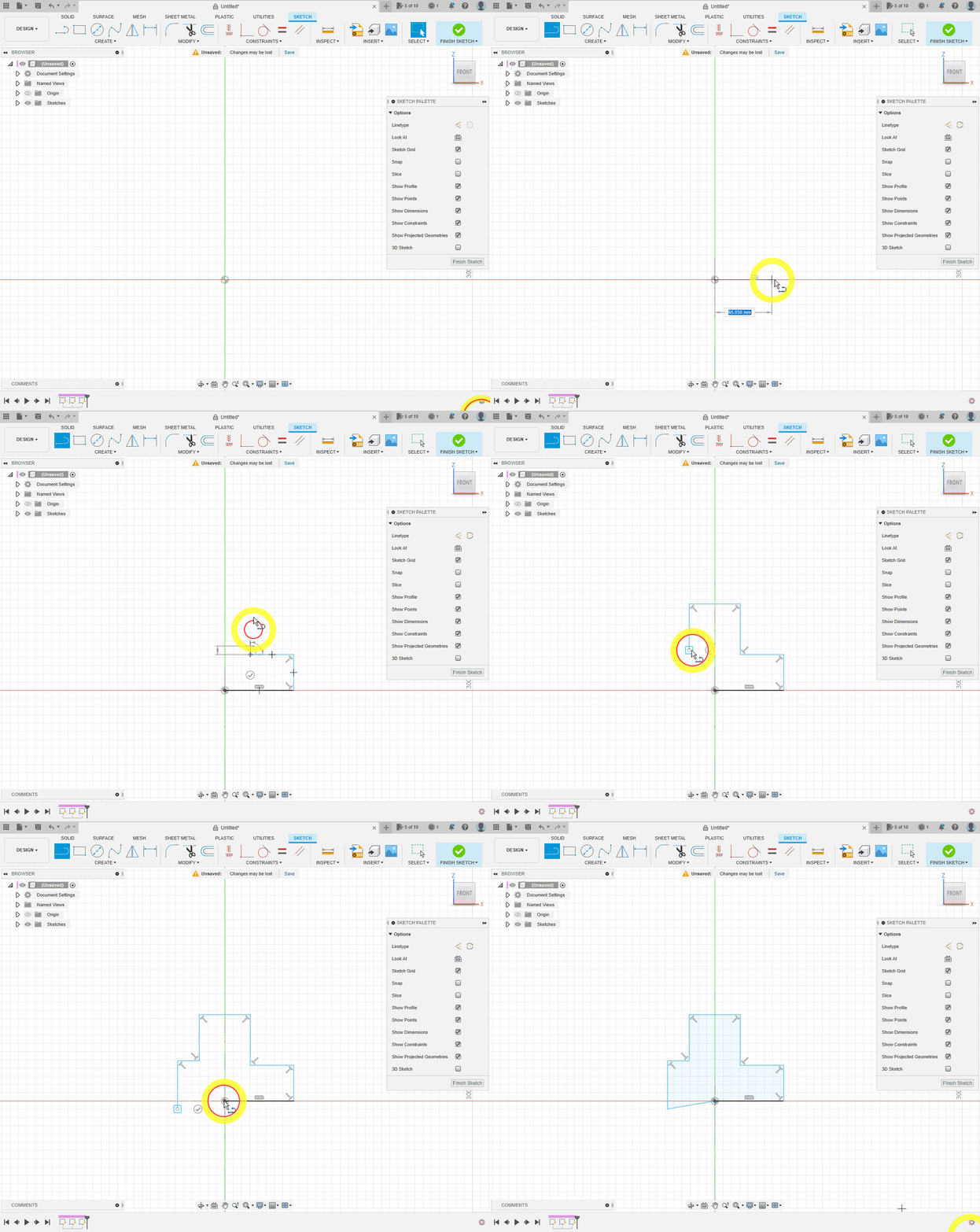
- Apply Horizontal/Vertical or Perpendicular to all suitable edges. Align the last edge with Collinear if needed.
- Draw a centreline through the origin and press
Xto make it construction geometry.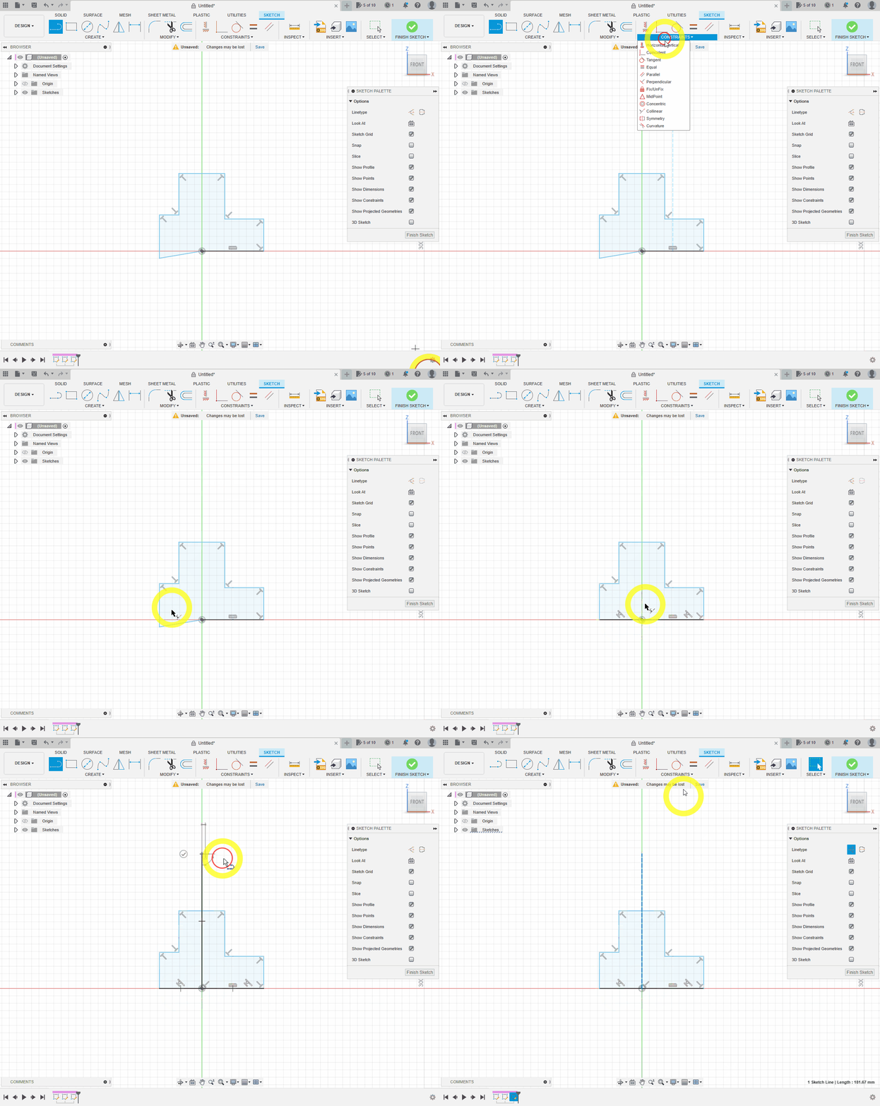
- Apply Symmetry to the vertical edges and Collinear to matching horizontal edges.
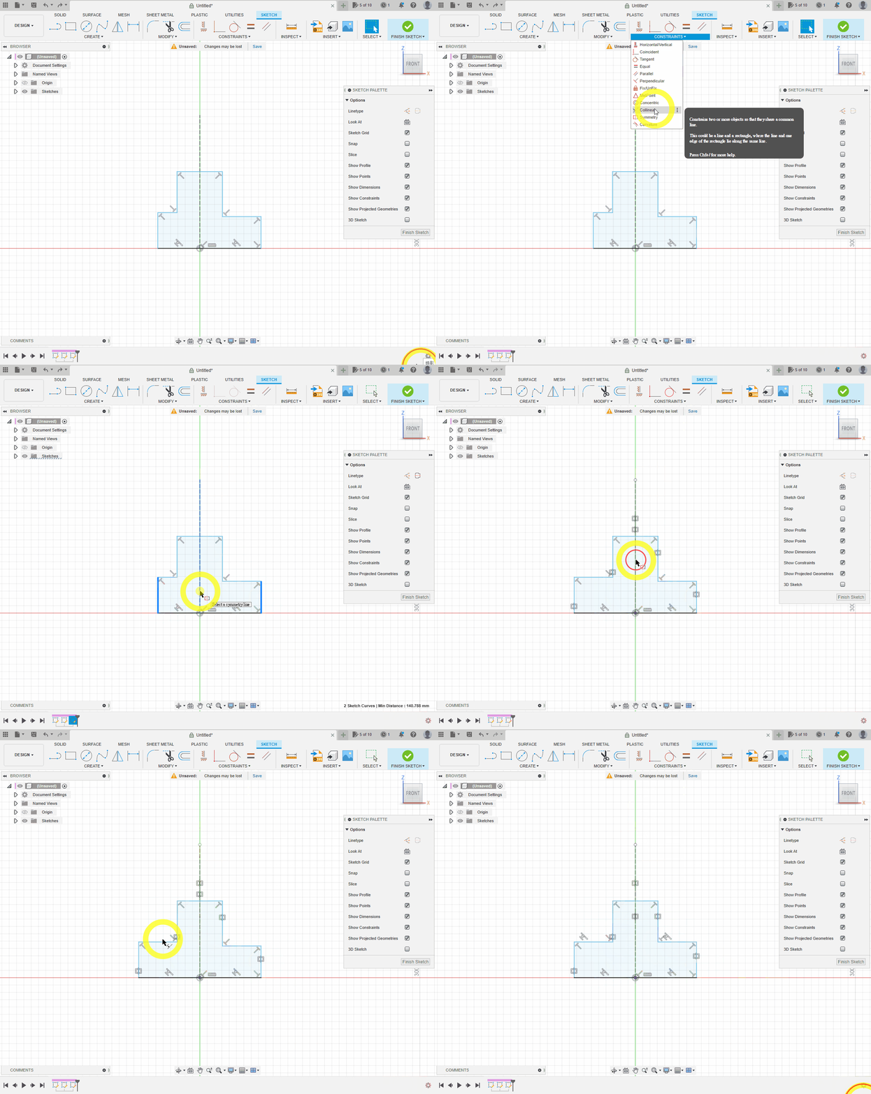
- Press
Dand add all dimensions. Some measurements must be defined between two selected points.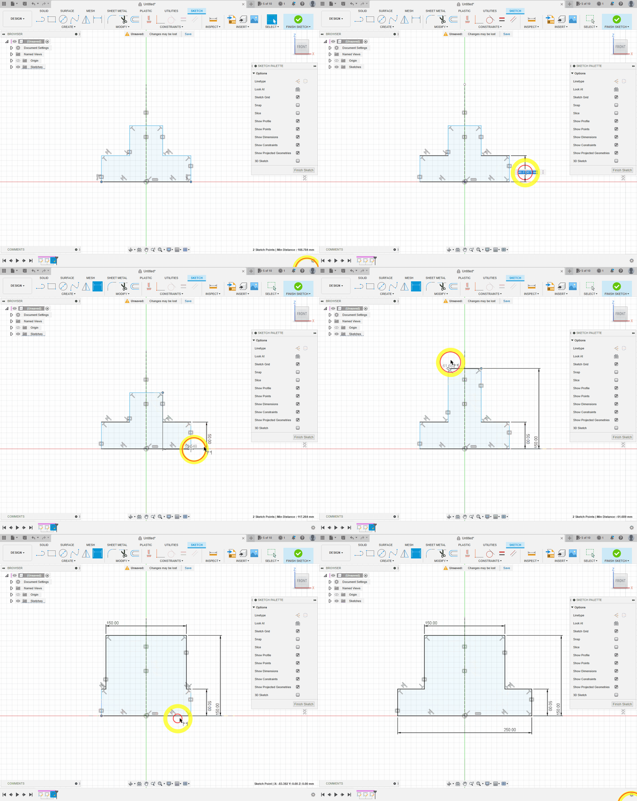
- Search for
Center Rectangleand draw a30 × 50 mmrectangle whose top is 20 mm below the highest point.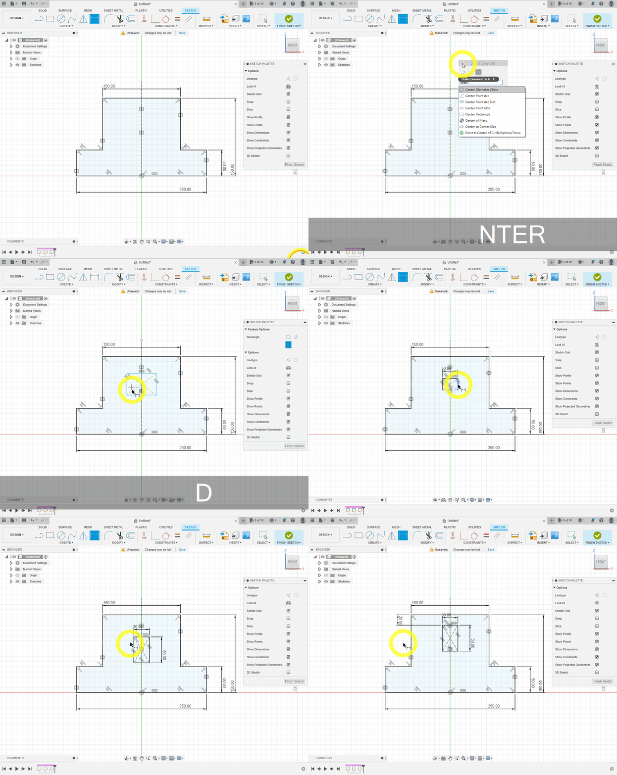
- Use
Center-to-Center Slotto create the slot. Apply Symmetry and add its dimensions.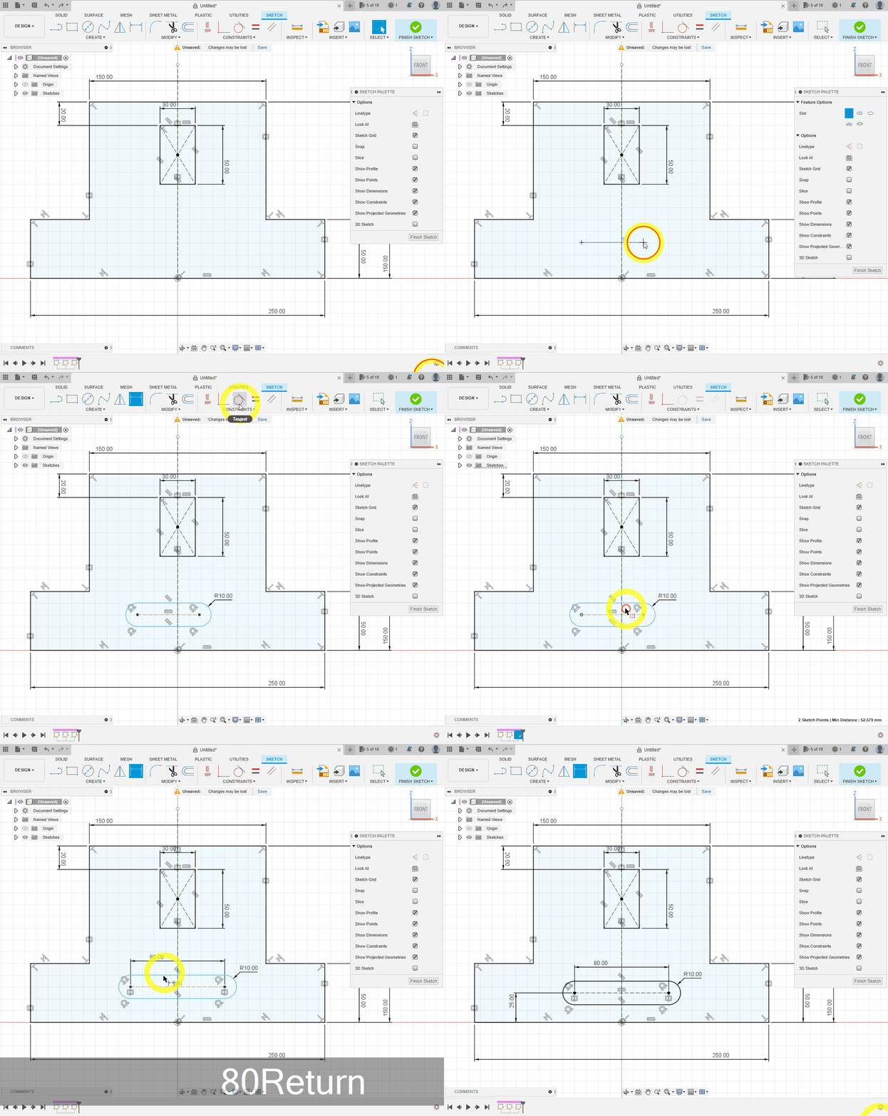
- Extrude by
10 mm.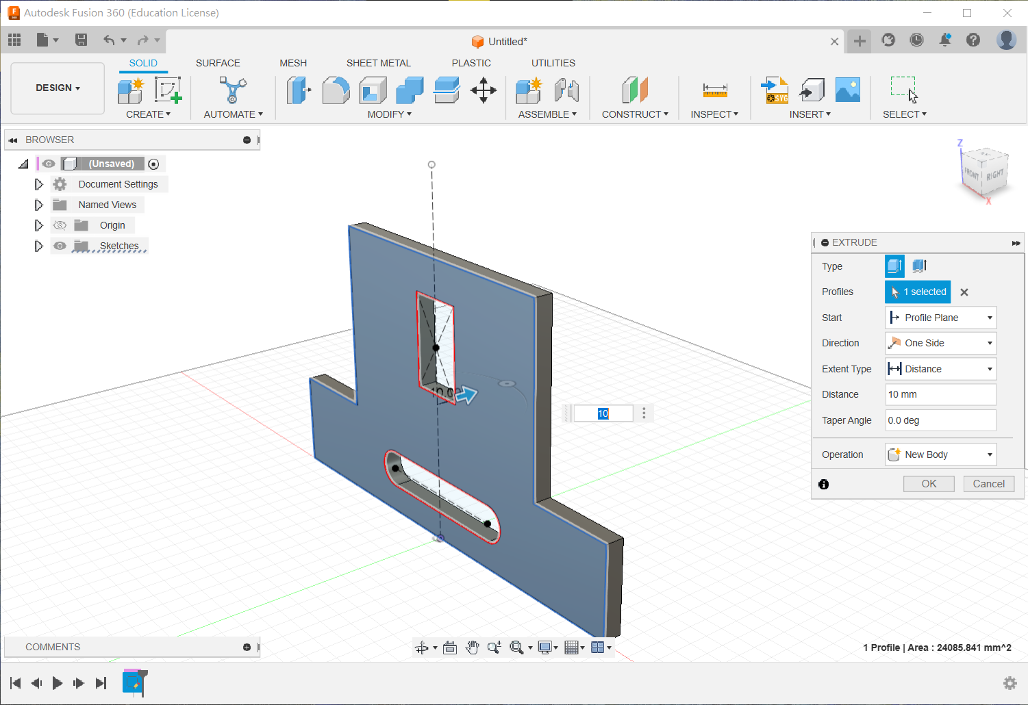
Exercises 4–6
Use Tangent, 3-Point Arc, Line and Circle.
Exercise 4
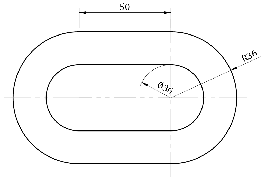
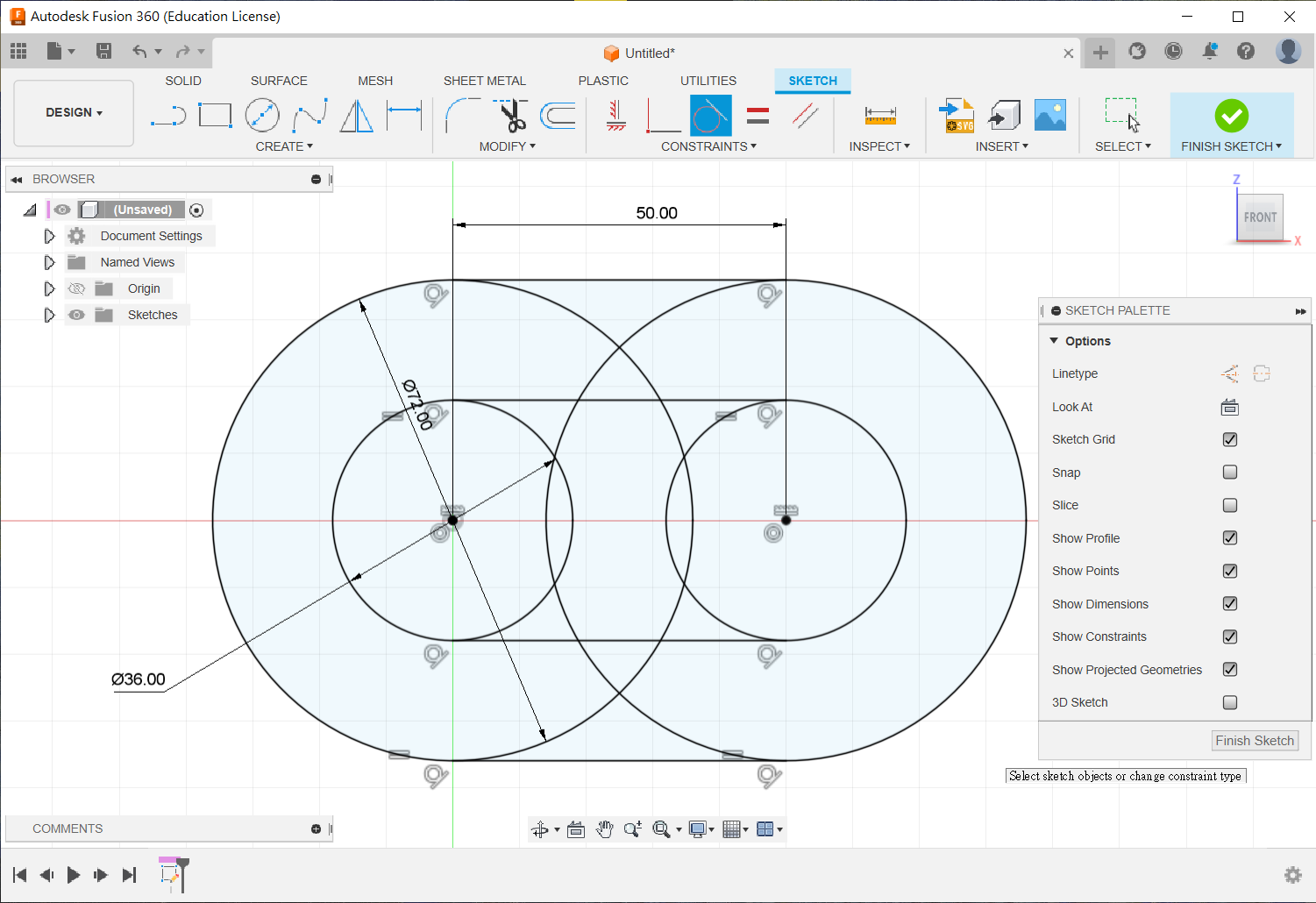
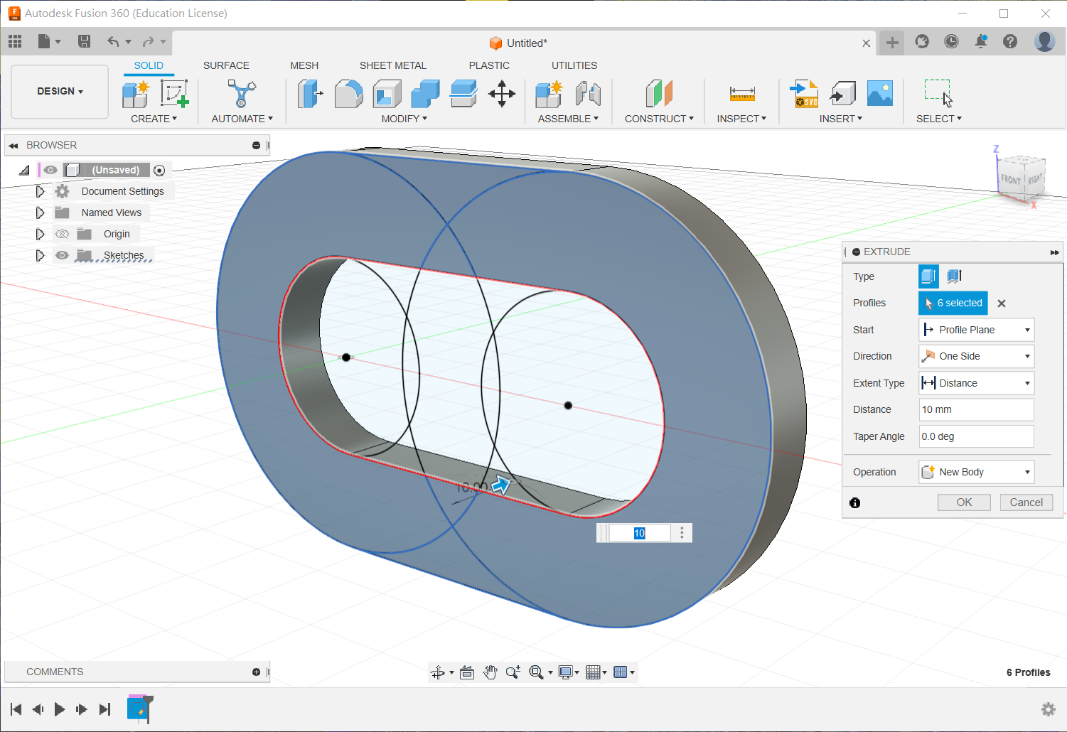
Exercise 5
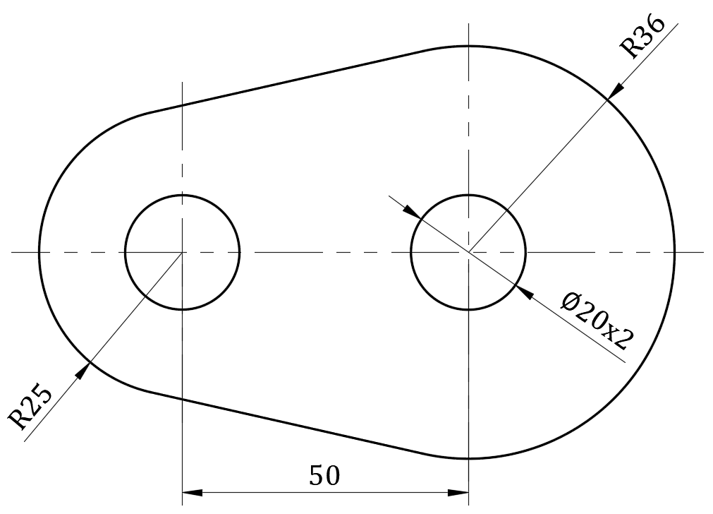
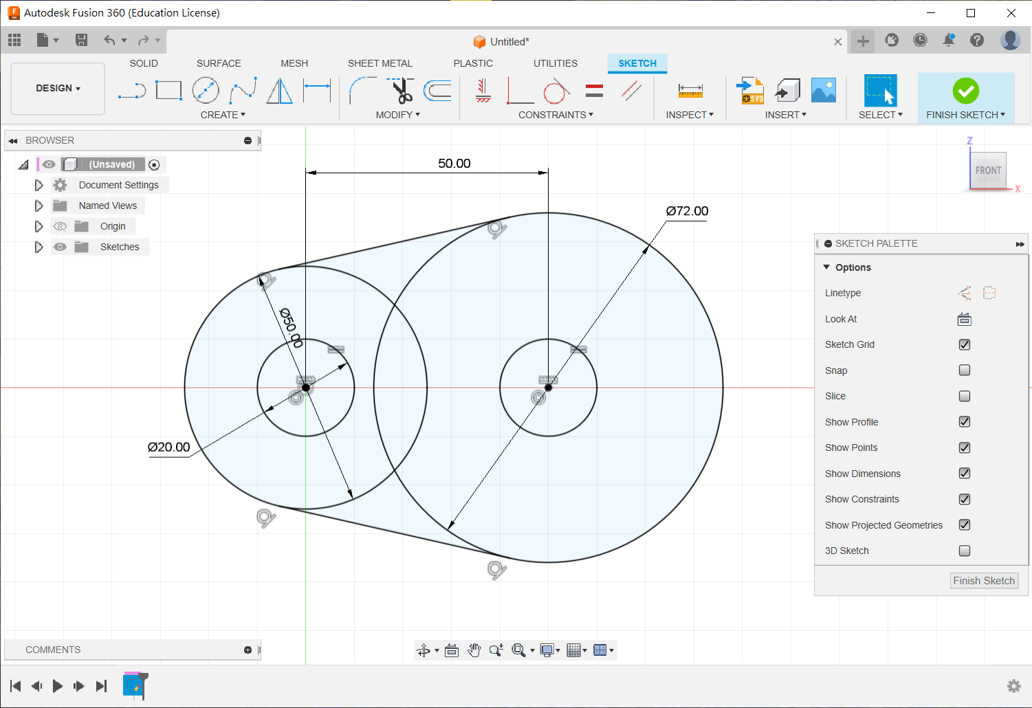
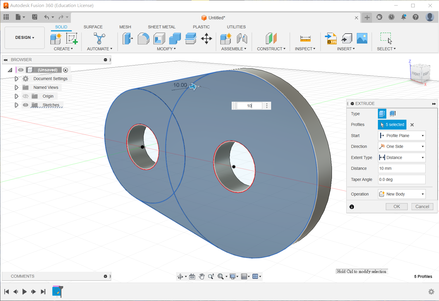
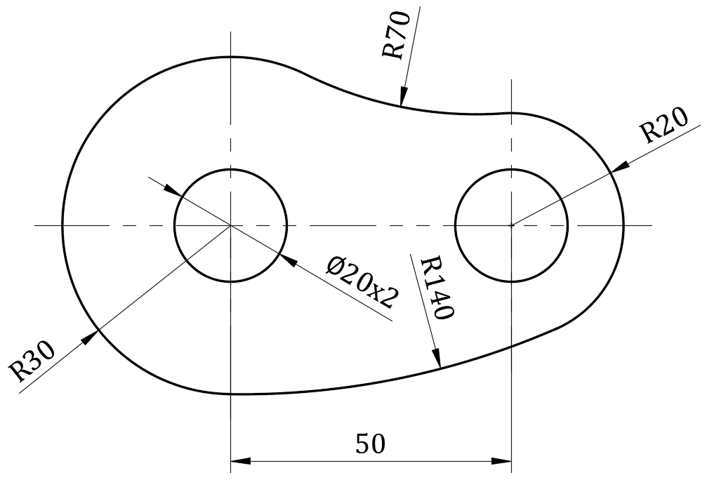
Exercise 6

Exercises 7–9
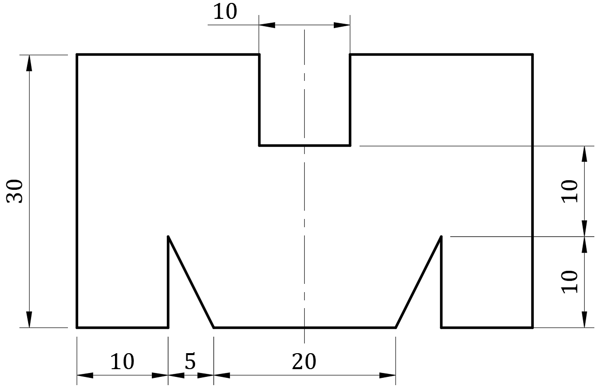
Use Symmetry, Tangent, Center Rectangle, 3-Point Arc, Line and Circle.
Exercise 7
Exercise 8
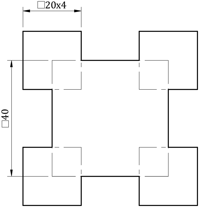
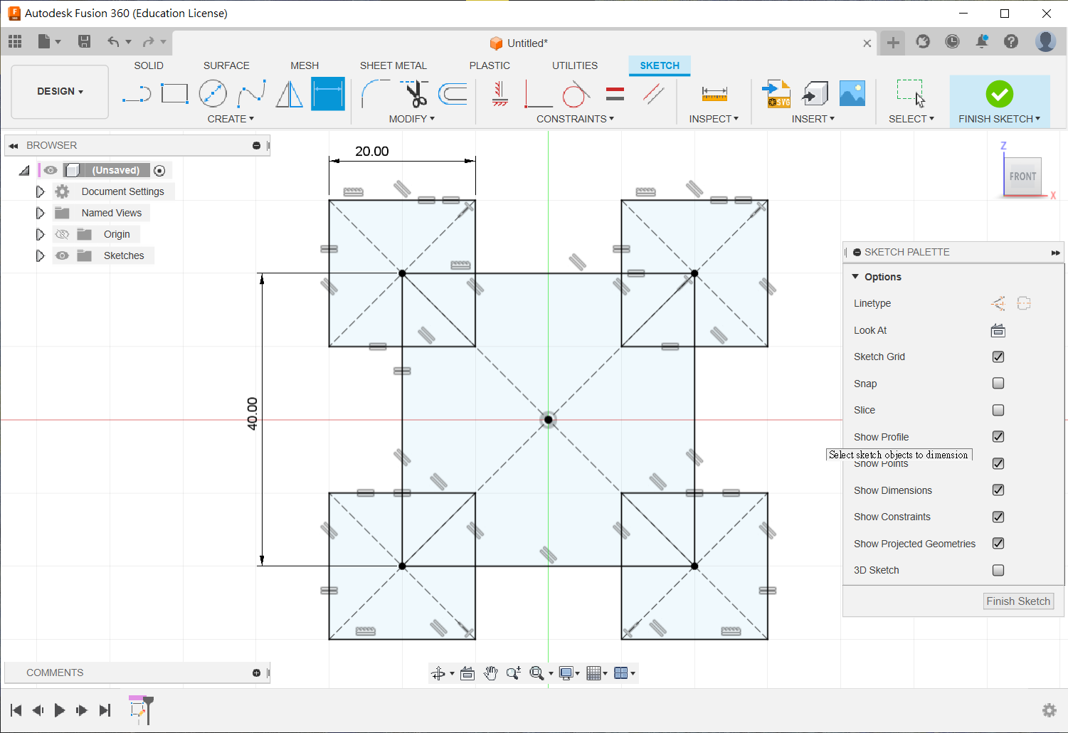
Draw the shapes with Center Rectangle before extruding. Do not delete the original construction lines, because that would break their constraint relationships.
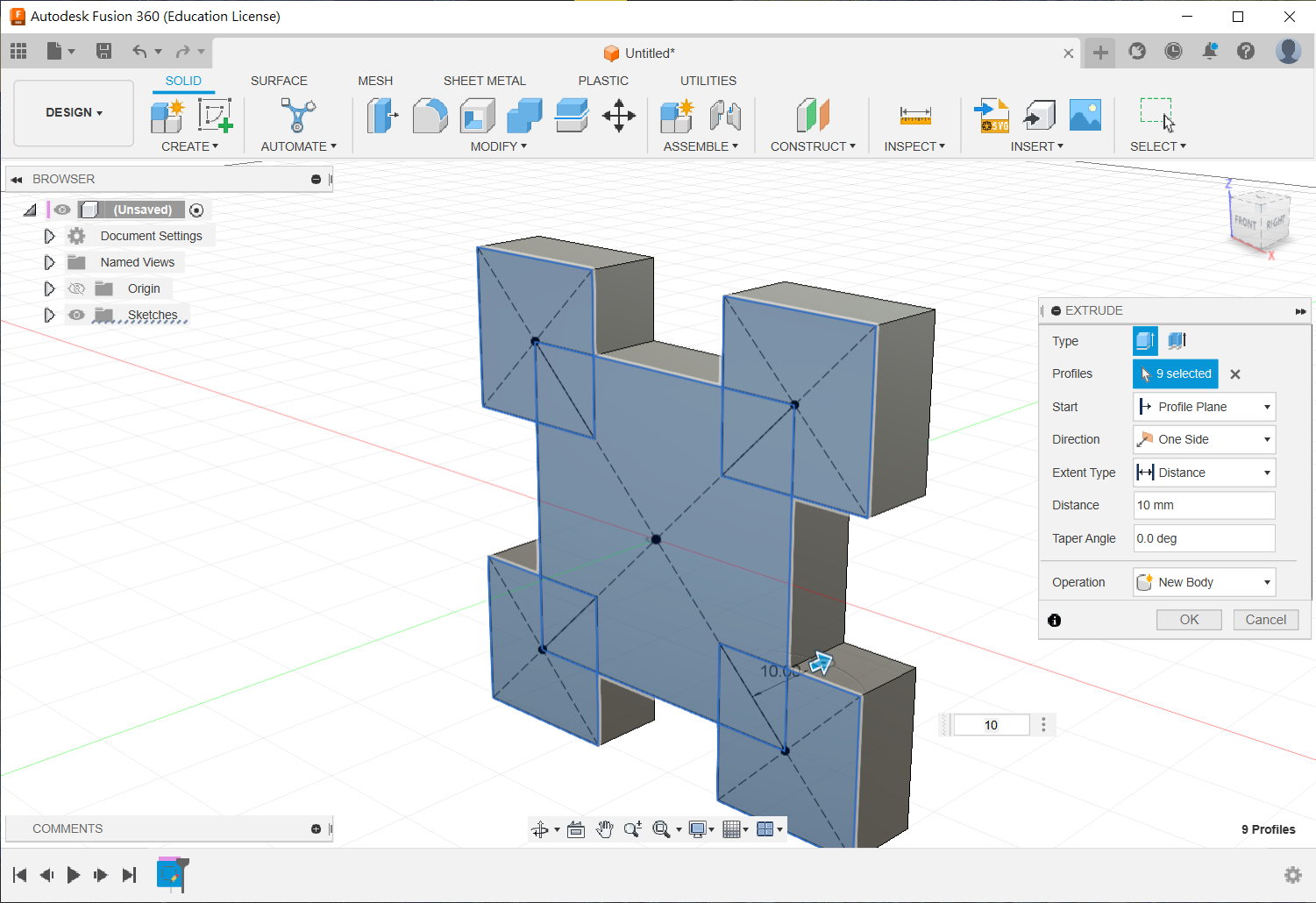
Exercise 9
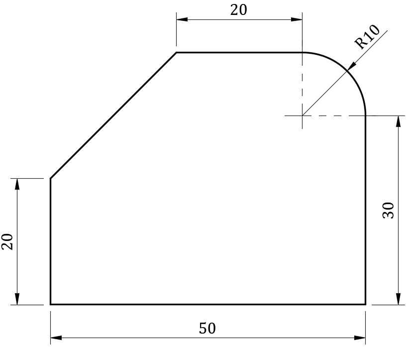
Either draw the R10 quarter-circle in the sketch or add it to the solid afterwards with Fillet.
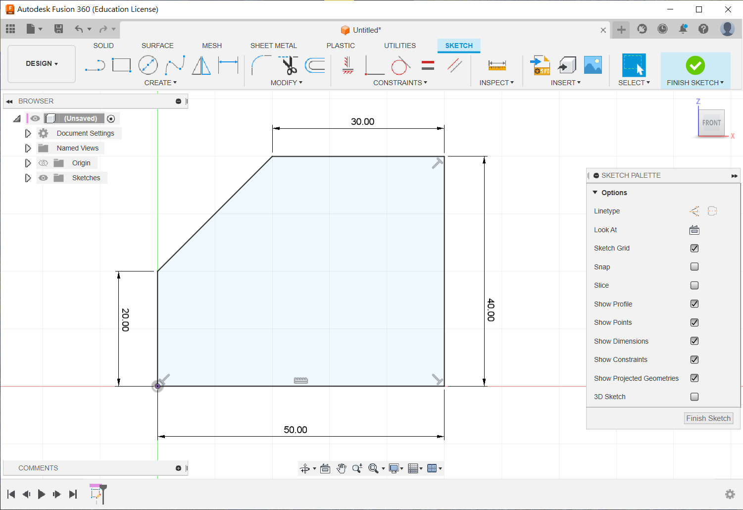
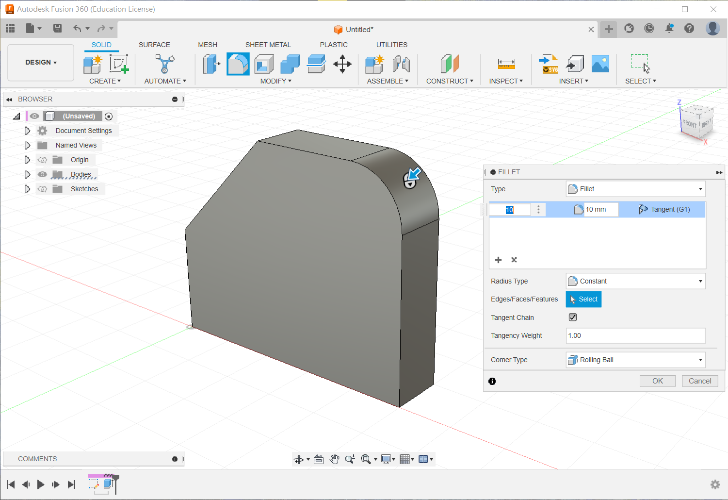
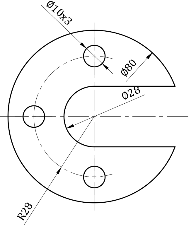
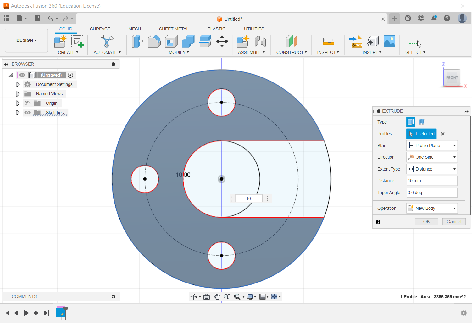
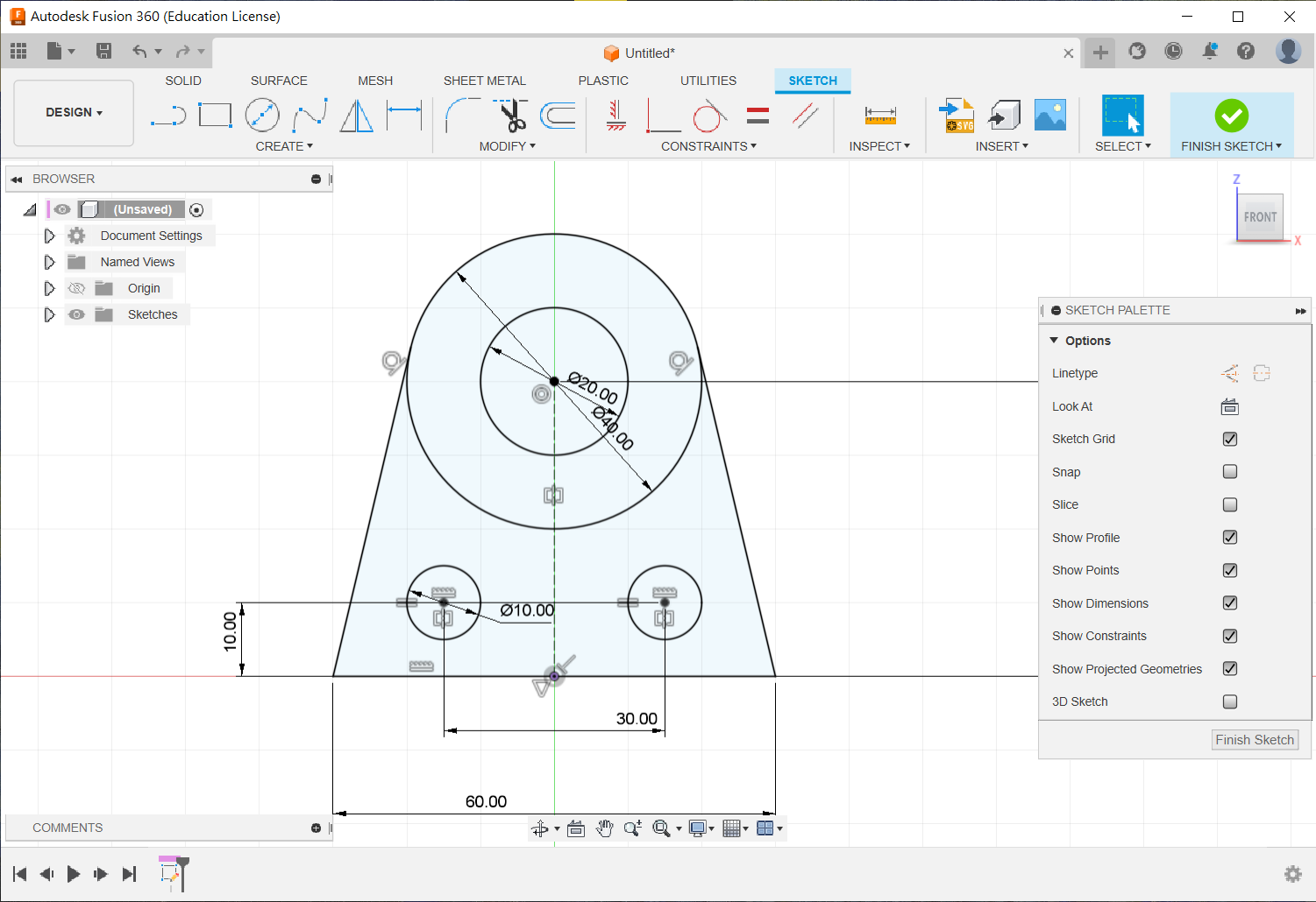
For the following exercises, draw complete circles and lines where practical. Avoid Trim and Fillet in the 2D sketch; applying them to the solid greatly reduces constraint errors.
Exercise 10
Exercise 11
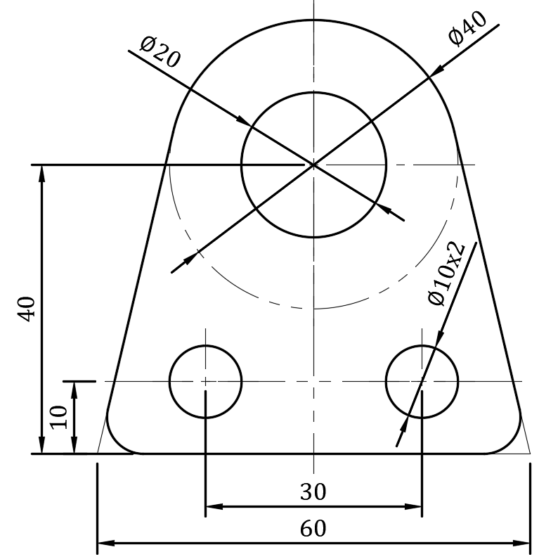
Do not fillet corners in the 2D sketch; fully constrained black lines may become under-constrained blue lines again.
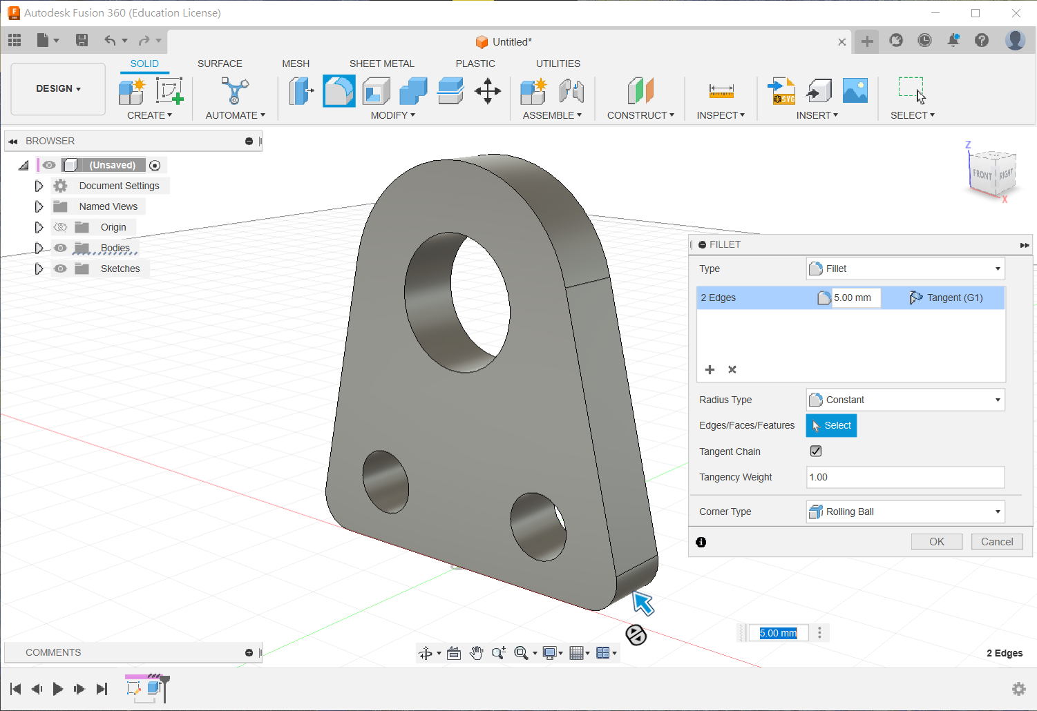
Exercise 12
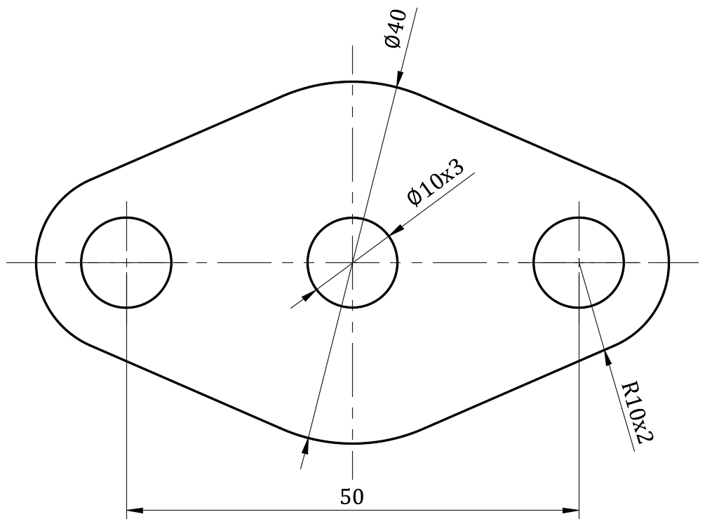
Avoid Trim in the 2D sketch because it can remove existing constraint relationships.
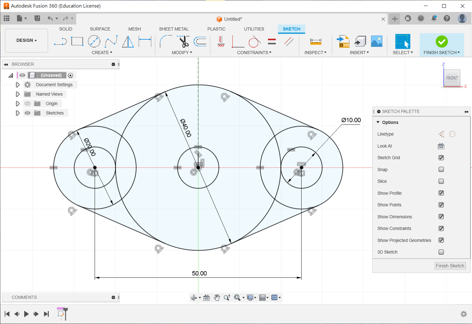
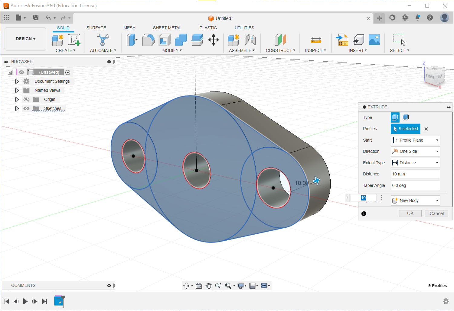
Exercise 13
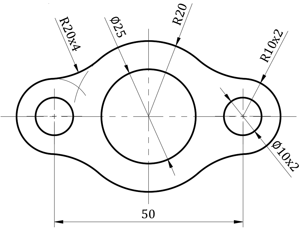
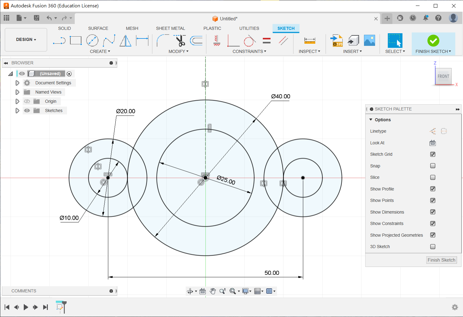
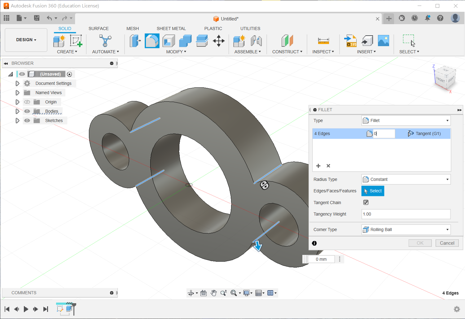
- Either draw the four arcs with
3-Point Arcbefore extruding, or ignore them initially and add them to the solid with Fillet.
Exercise 14
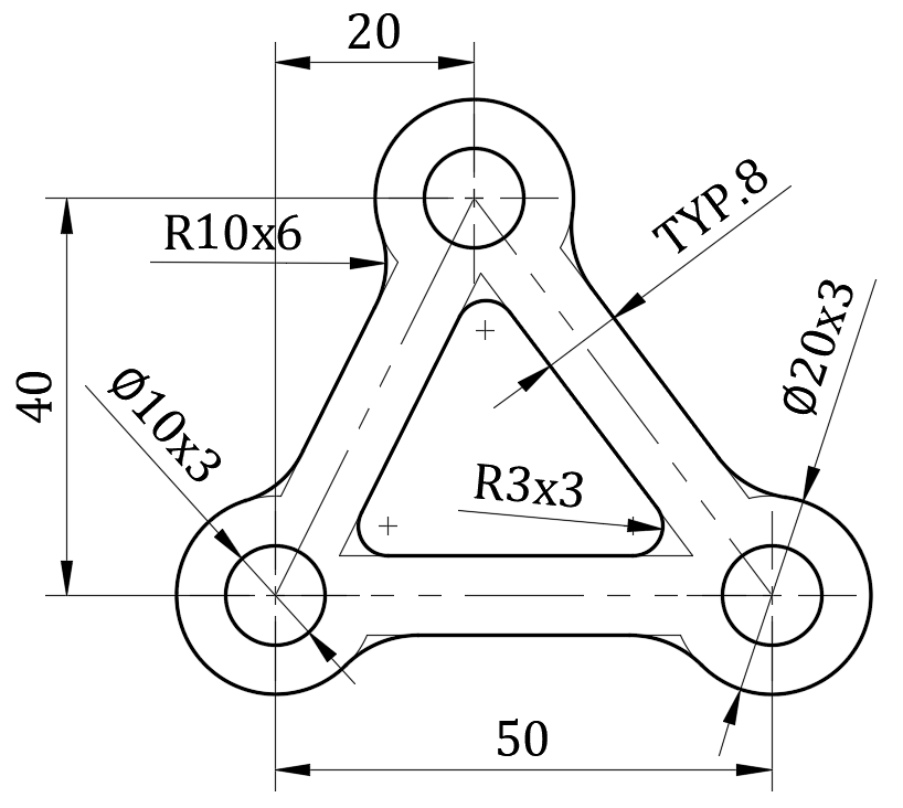
Harder problem: both rounded areas are easier to add as 3D fillets.
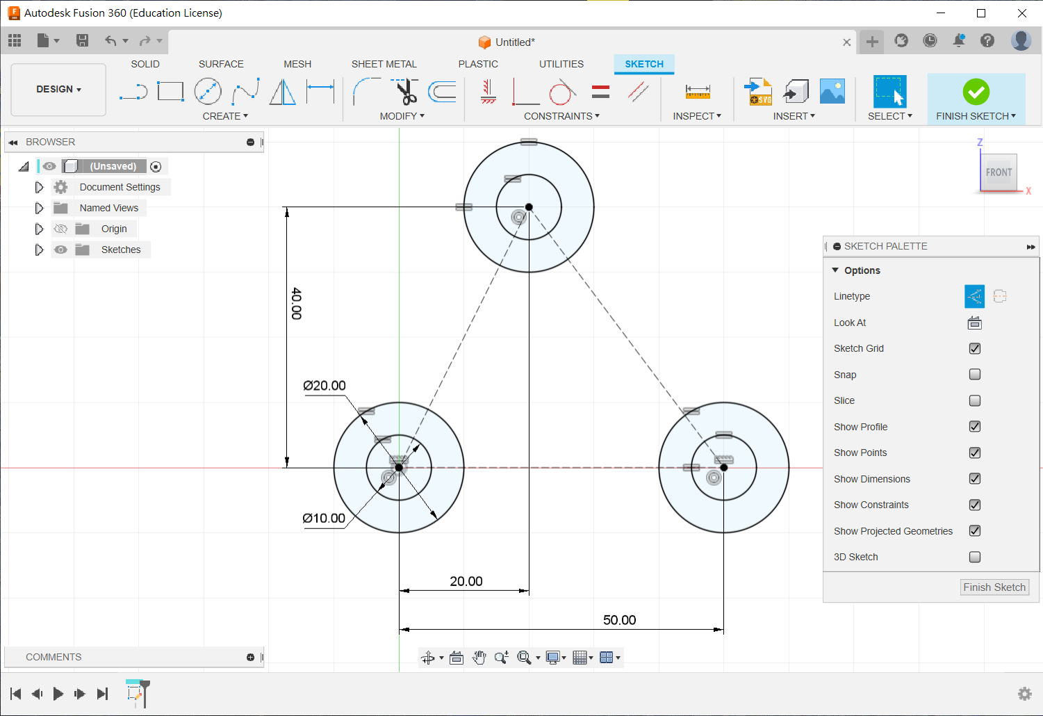
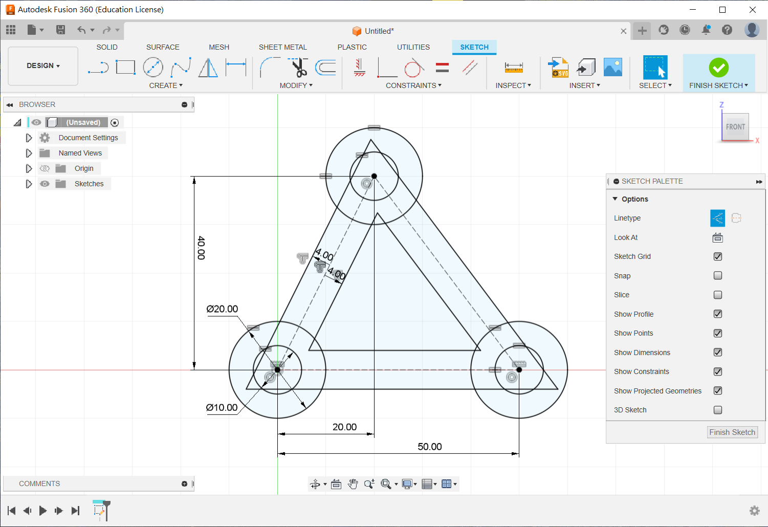
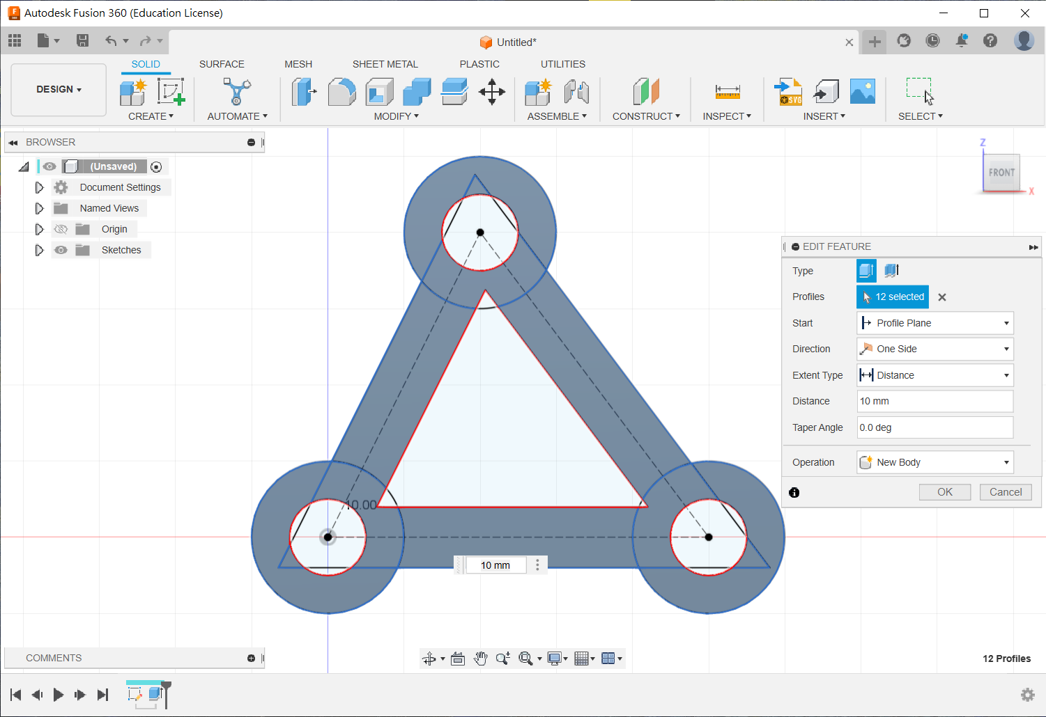
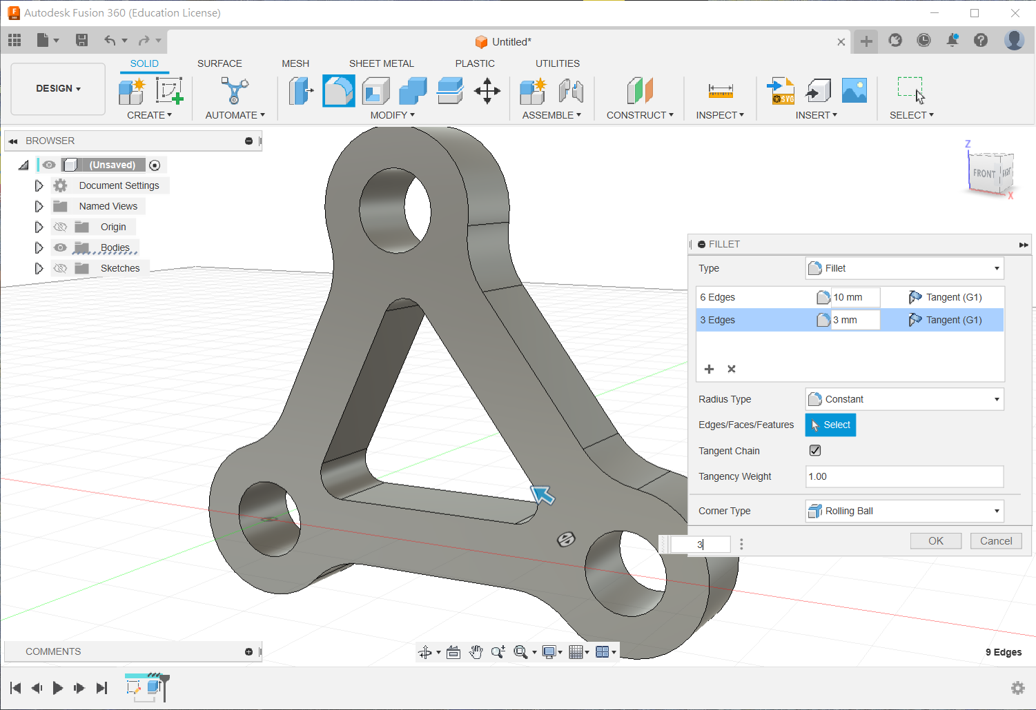
Exercise 15

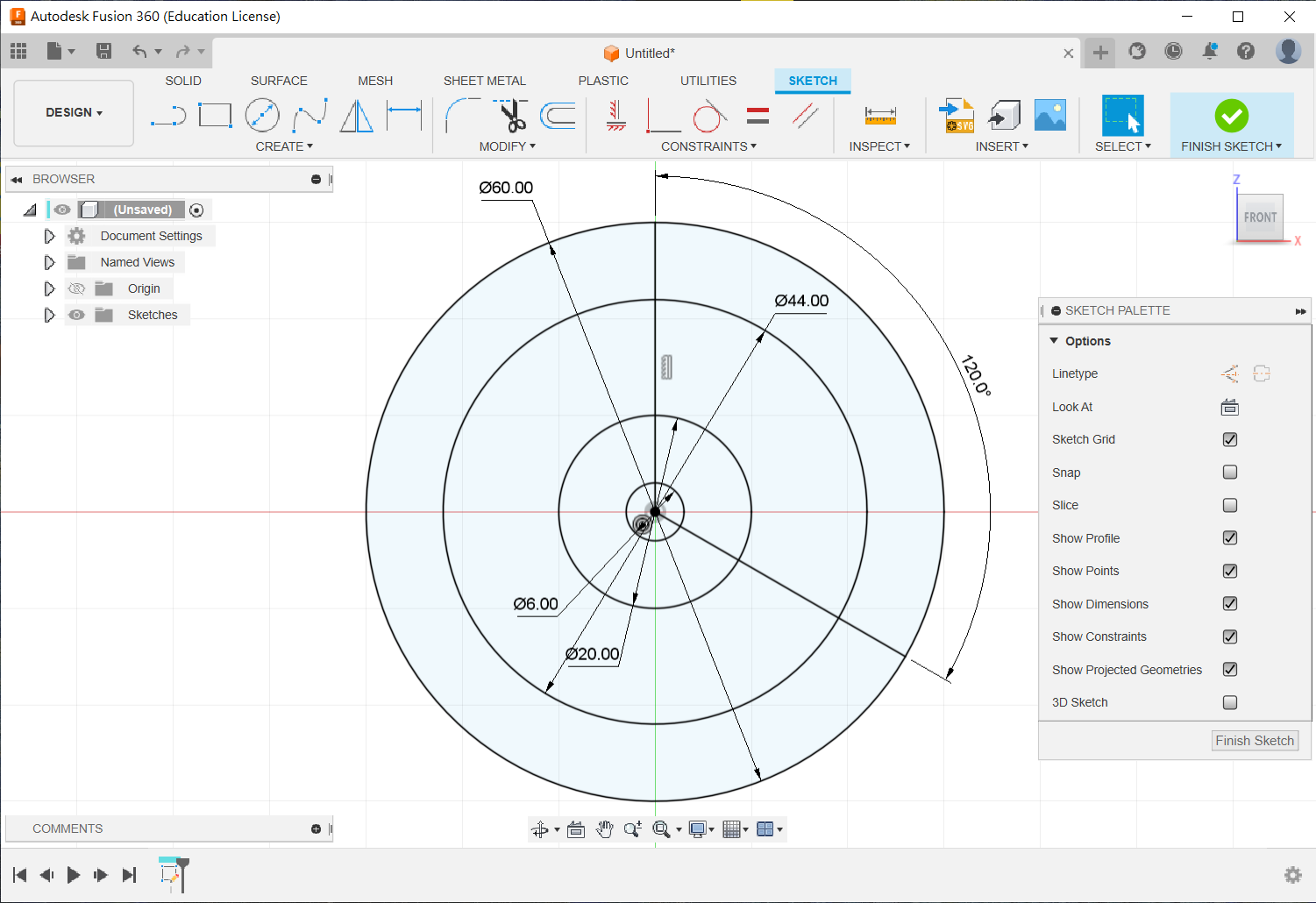
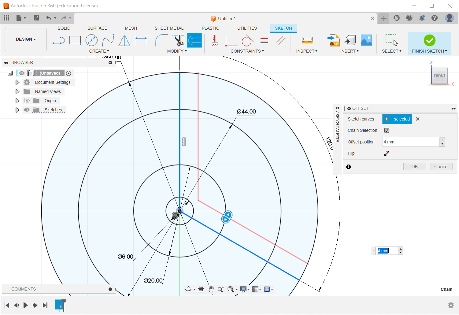
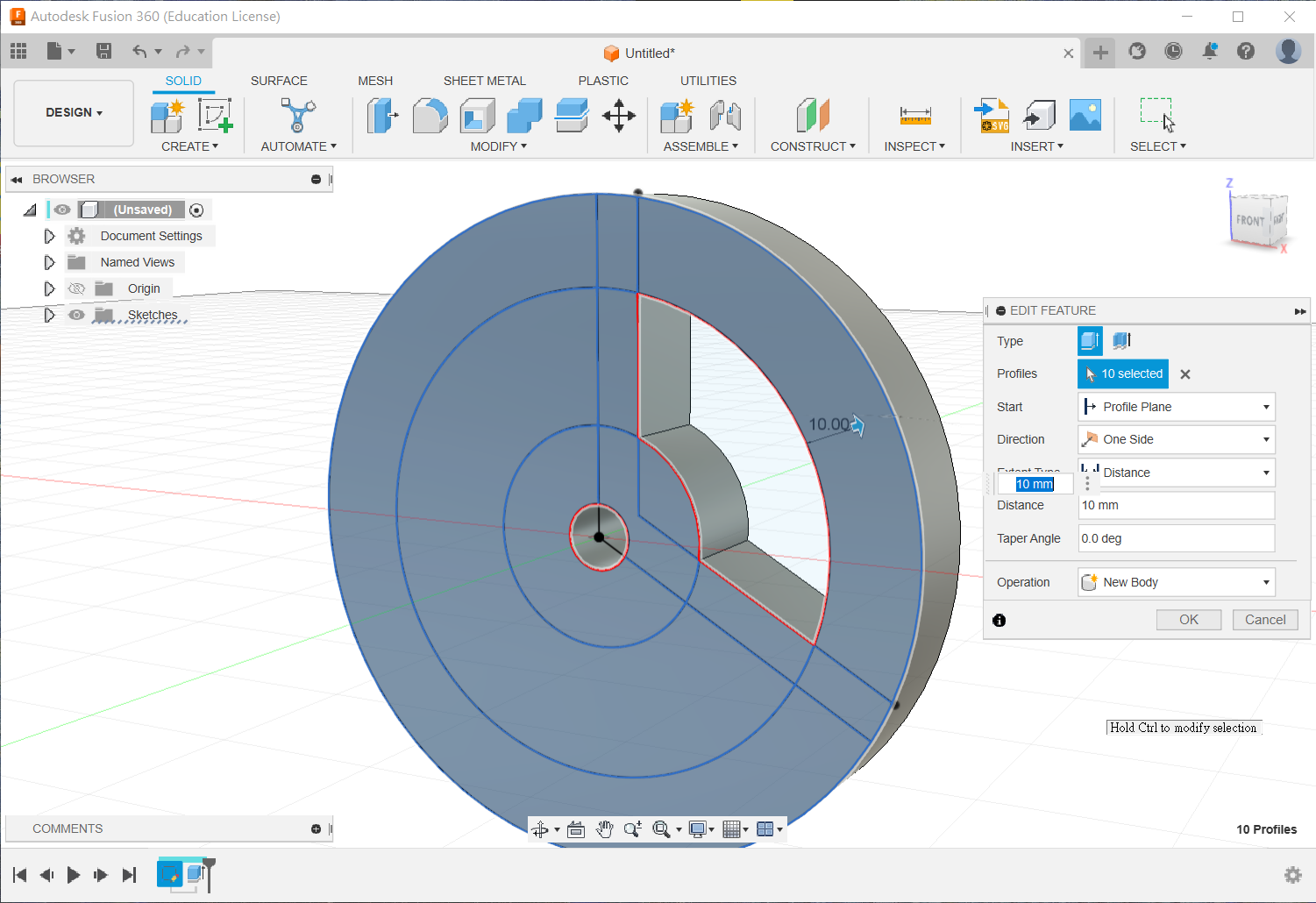
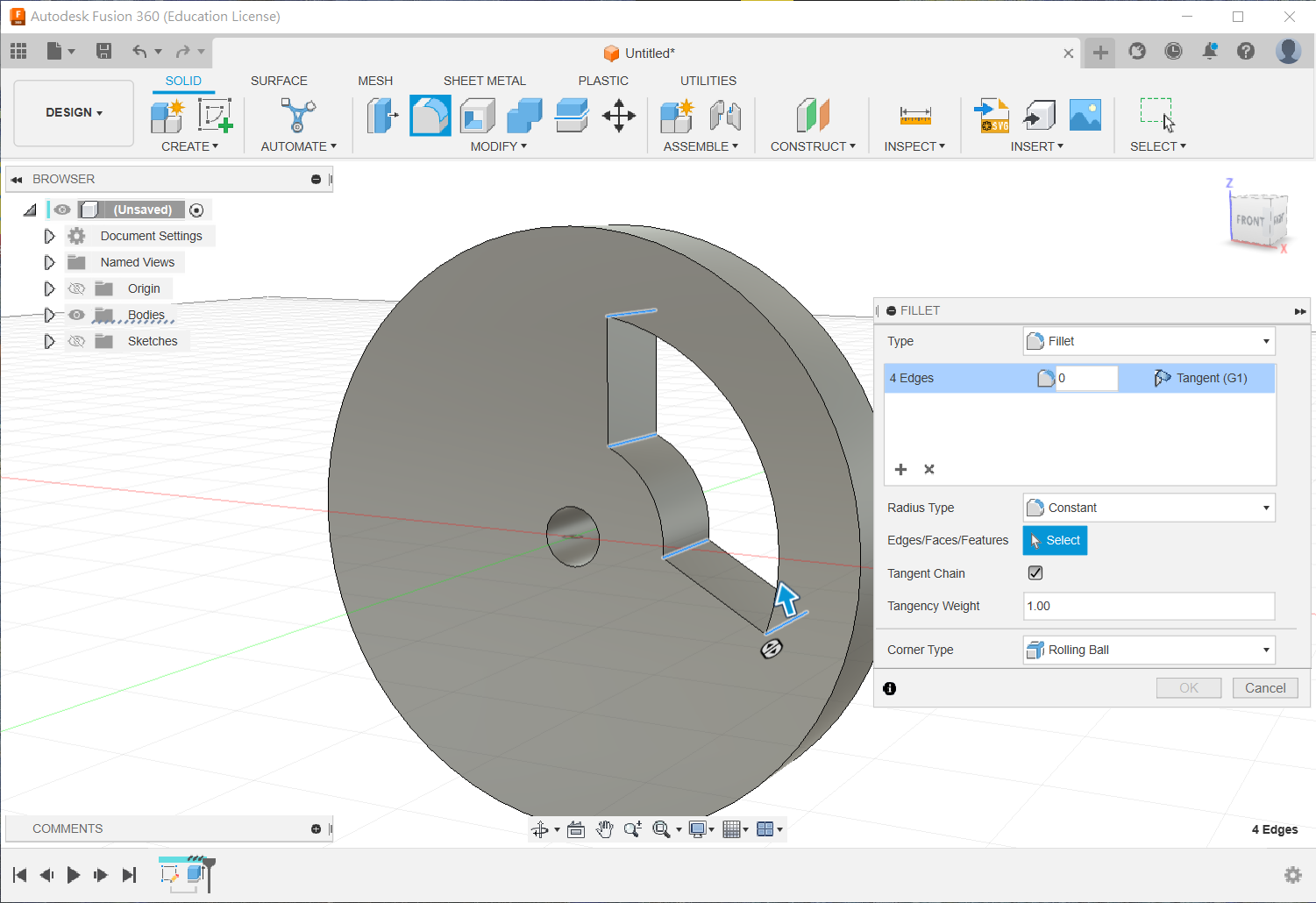
Translation notice: This English page was generated automatically by AI and has not yet been reviewed by a human. It will be checked and revised page by page when time permits.