Engraving a Nameplate
As a warm-up, this chapter introduces basic CNC operation and shows how to engrave text in Fusion 360, generate toolpaths and export G-code.
ℹ️INFO
Fusion 360 integrates CAD, engineering and CAM. Here its Manufacture workspace generates the CNC program.
1. Create the CAD Model
1.1 Create the Wooden Plaque
- Create a new Fusion 360 component named
Name Tag. - Create a sketch in the Top view.
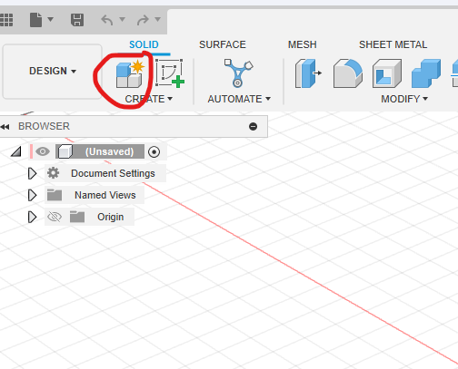
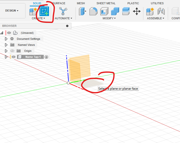
- Press
S, findCenter Rectangleand draw a50 × 25 mmrectangle. - Press
Eand extrude it by3 mm.
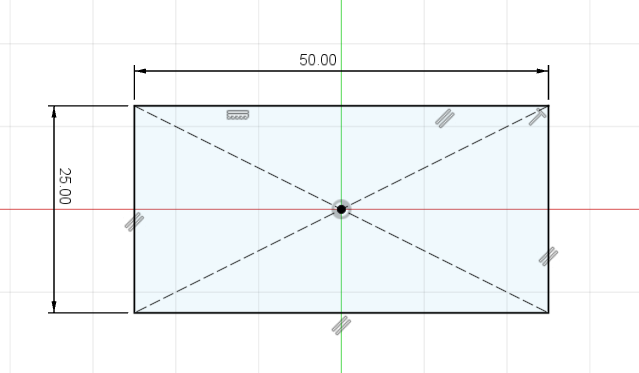
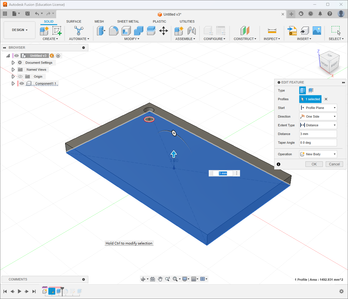
Optionally press A, choose a wood appearance and drag it onto the body.
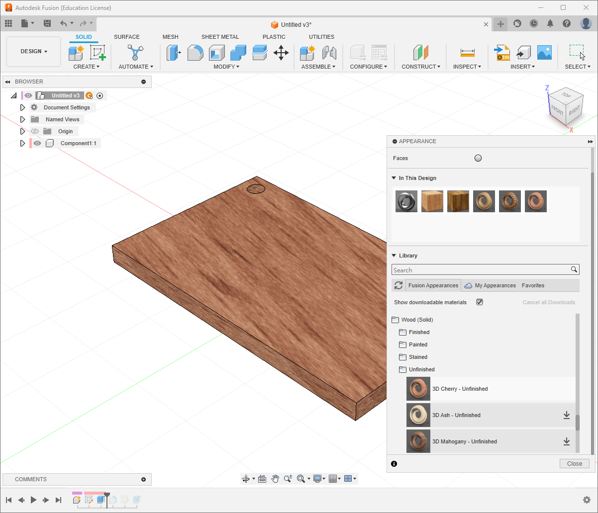
1.2 Create and Cut the Text
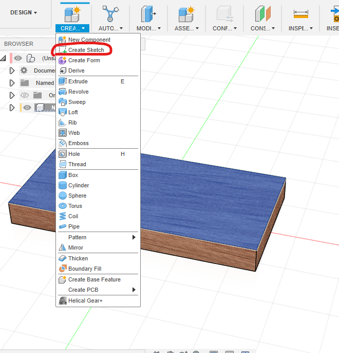
- Create a sketch on the plaque's top face.
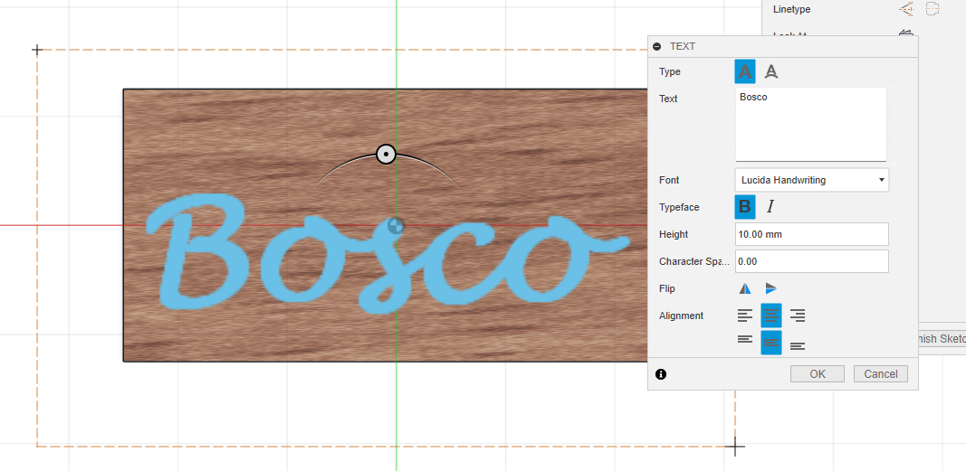
- Draw a text box and enter a name; this example uses
Bosco, after St John Bosco. - Choose an appropriate font and size, with both vertical and horizontal alignment centred.
- Not every font can be extruded, and very thin strokes may be beyond the machine's engraving accuracy.
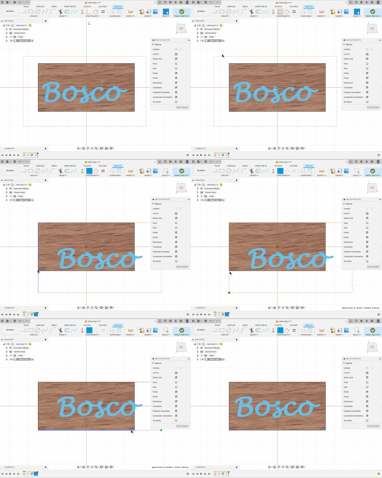
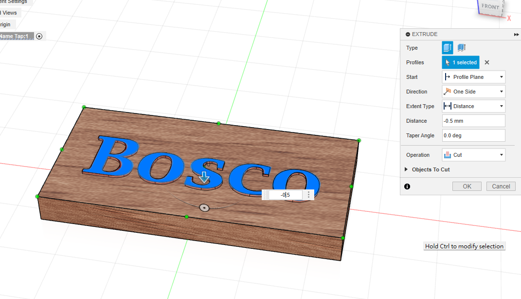
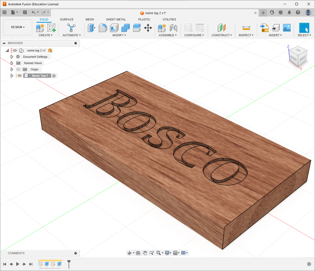
Apply Coincident between the upper-left text-box corner and plaque corner, then repeat at the lower-right. Press E and extrude the text by -0.2 mm; the operation should become Cut.
2. Generate Toolpaths
2.1 Setup
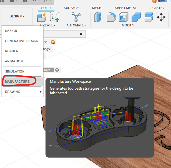
Choose MANUFACTURE from the workspace selector.
Choose SETUP, then select the machine.
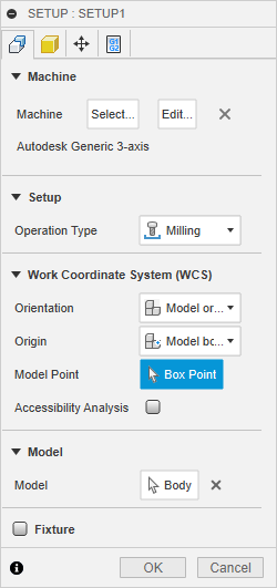
In Fusion Library, select the generic three-axis configuration Y axis on the Table and XZ axis on the Head. Fusion downloads a machine model for simulation.
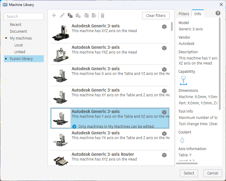
- Leave
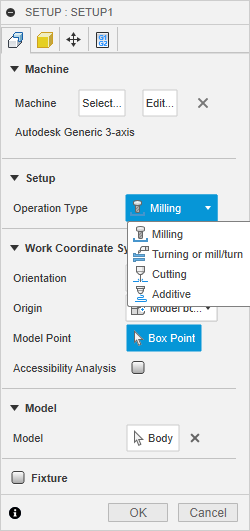
Operation TypeasMilling. - Under Work Coordinate System, set
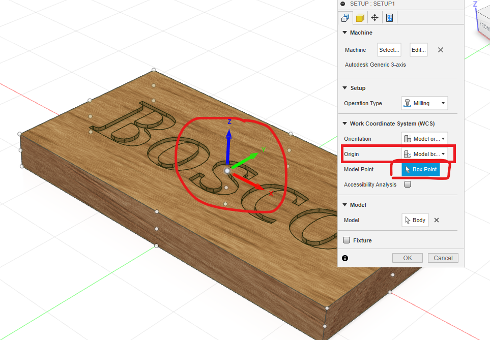
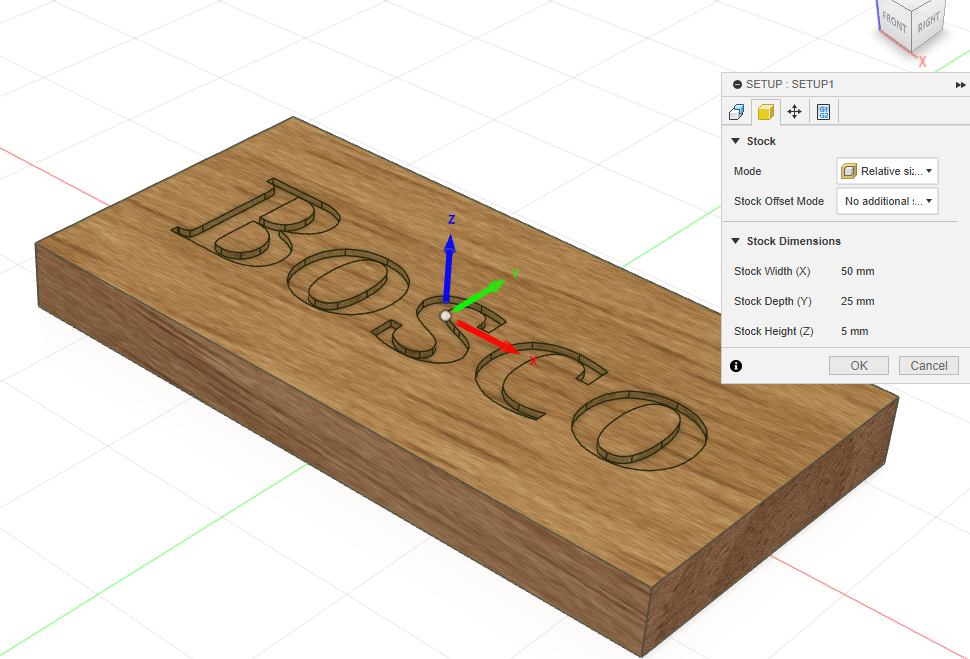
OrigintoModel box point, then select the centre point on the top of the plaque. Confirm that X, Y and Z point in the same directions as shown; otherwise correctOrientationfirst. - Select the plaque under
Model. - Leave
Fixtureempty for this exercise. A fixture model is normally used to detect collisions with clamps and vices.
On the Stock tab, choose Relative size box and set Stock Offset Mode to No additional stock. Normally stock is larger than the finished part, but this exercise only engraves the centre of an already-sized plaque.
2.2 Define the Tool
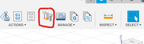
Open Manage → Tool Library, or search for it with S.
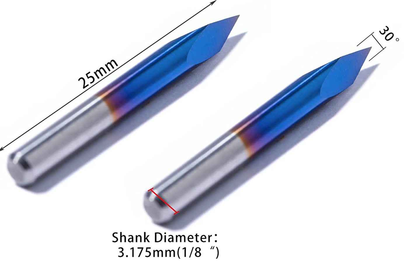
The tool is a 30° engraving cutter with a 0.1 mm tip.
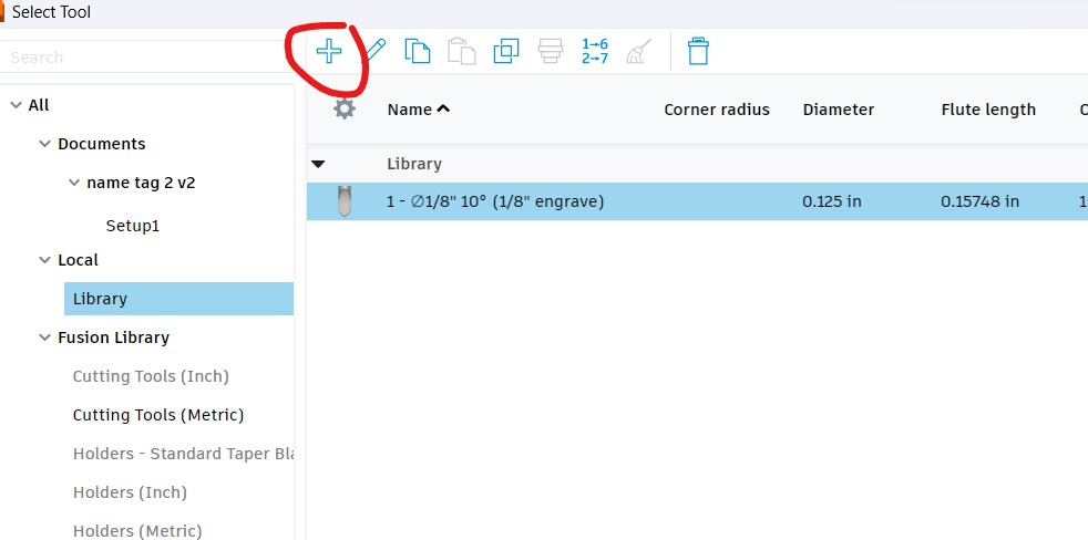
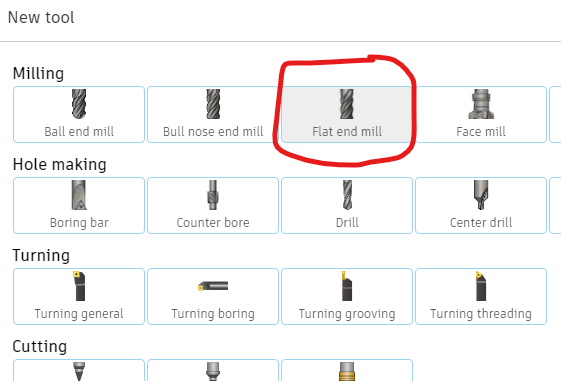
Click + to add a tool. Define it as a Flat End Mill, not an Engrave/Chamfer Mill, because the latter does not support the multi-depth workflow used here and may attempt the full depth in one pass.
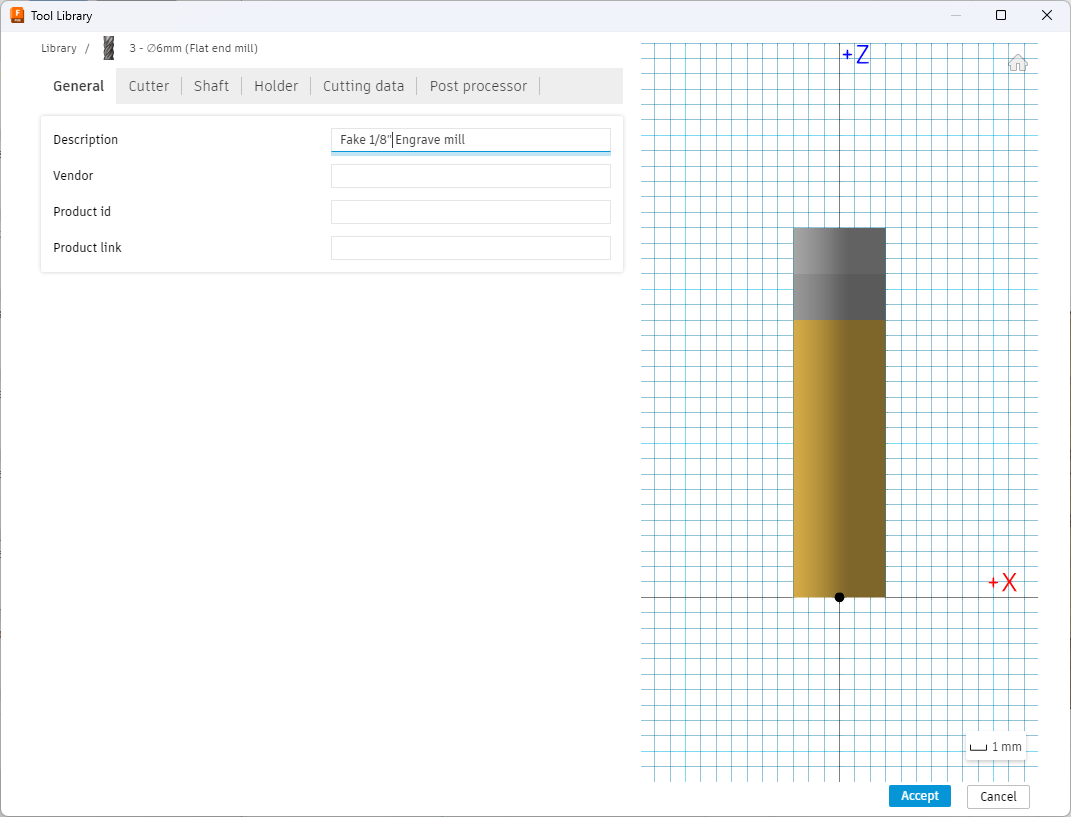
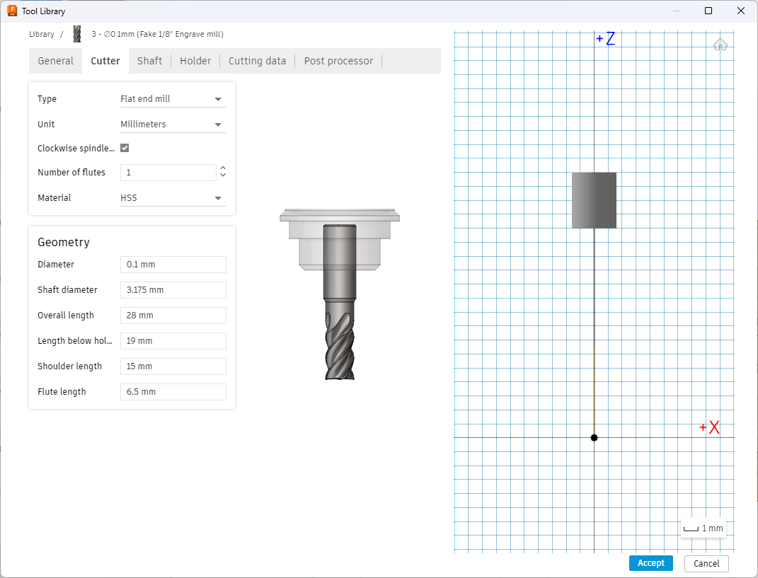
Enter:
- Description:
Fake 1/8" Engrave mill - Diameter:
0.1 mm(tip diameter) - Shaft diameter:
3.175 mm(1/8 inch) - Overall length:
28 mm - Length below holder: approximately
19 mm - Shoulder length:
15 mm - Flute length:
6.5 mm
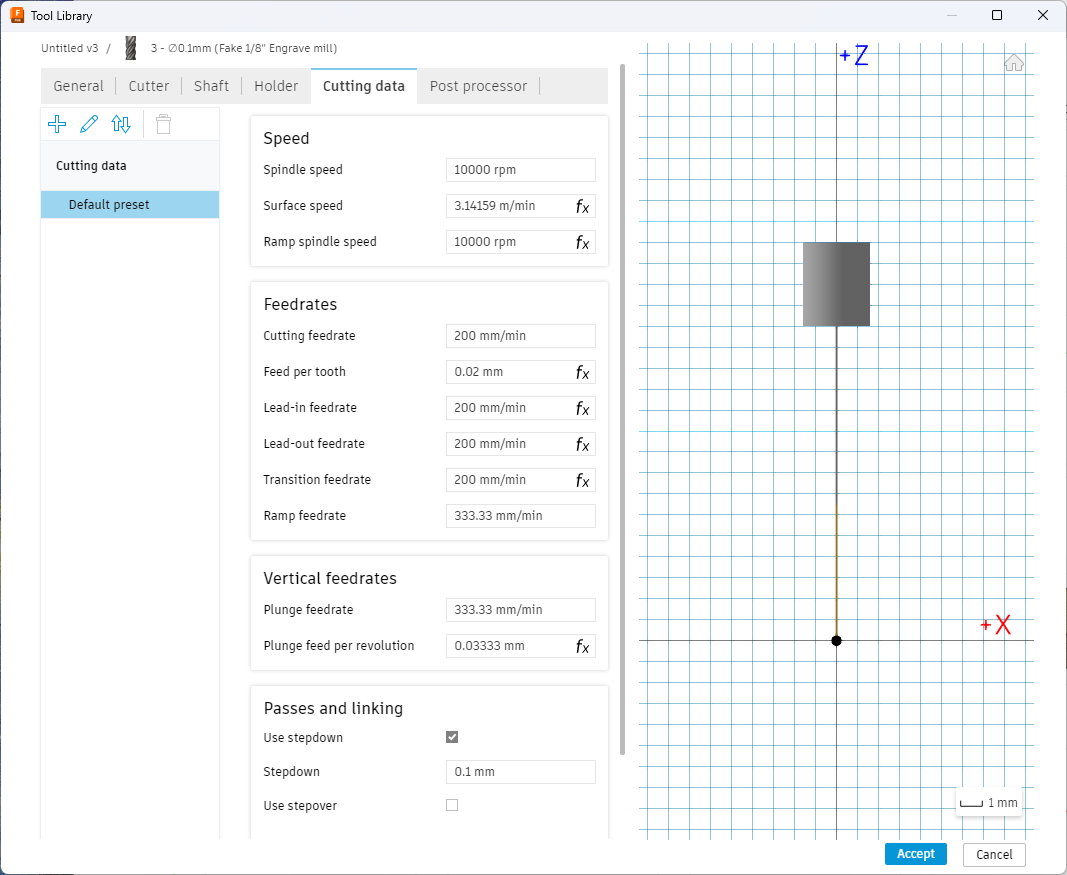
The Shaft and Holder tabs mainly affect collision simulation and may be skipped here. Under Cutting Data, set:
- Spindle speed: approximately
10,000 RPM - Cutting feed rate:
200 mm/min Use stepdown: enabled- Stepdown:
0.1 mm - Coolant:
Disabled
ℹ️INFO
Safe feeds and speeds depend on tool geometry, cutting depth, workpiece material and machine rigidity. The values here apply to the demonstrated machine and shallow wood engraving; do not assume they are correct for another machine or material. This CNC test video compares different spindle and feed rates on the same type of machine.
2.3 Generate the Toolpath
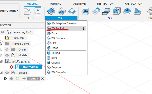
Choose 2D → 2D Pocket.
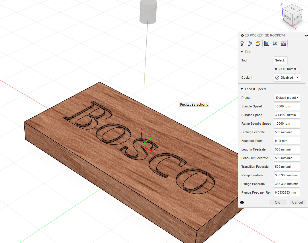
On the Tool tab, click Select and choose the tool just created.
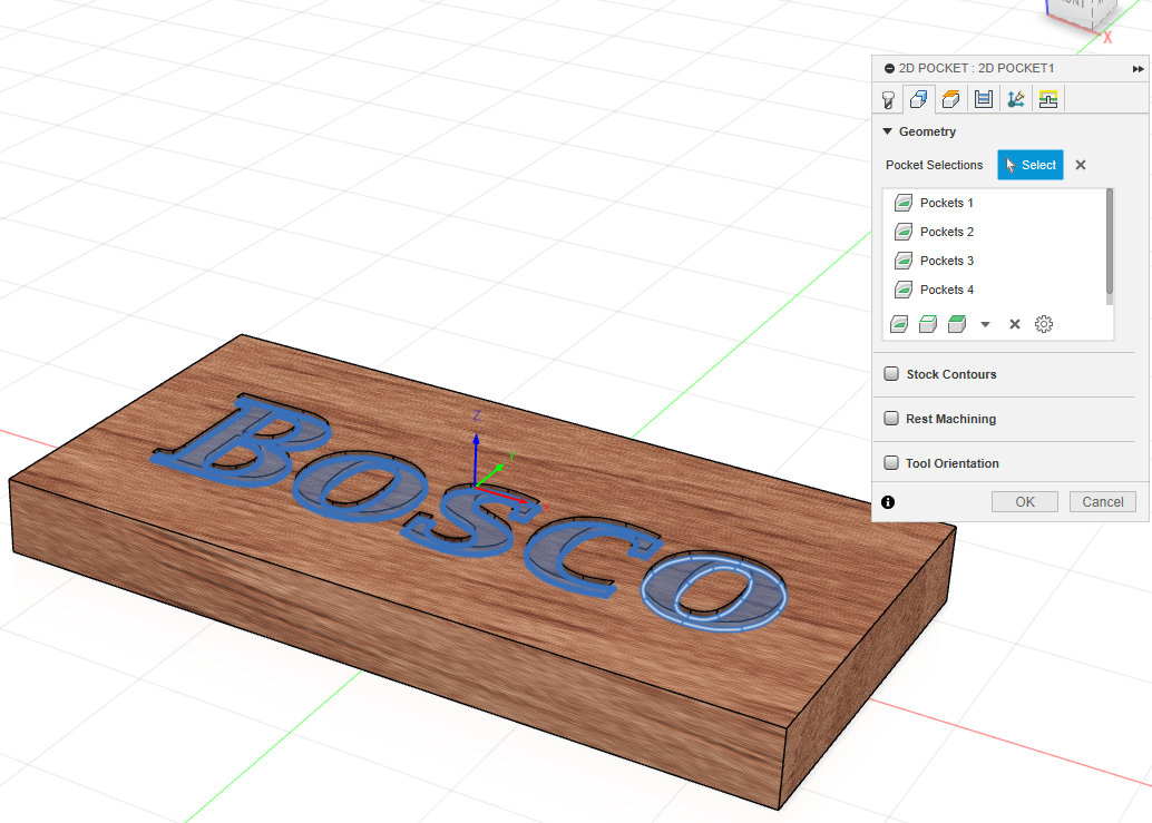
On Geometry, select the five letter faces.
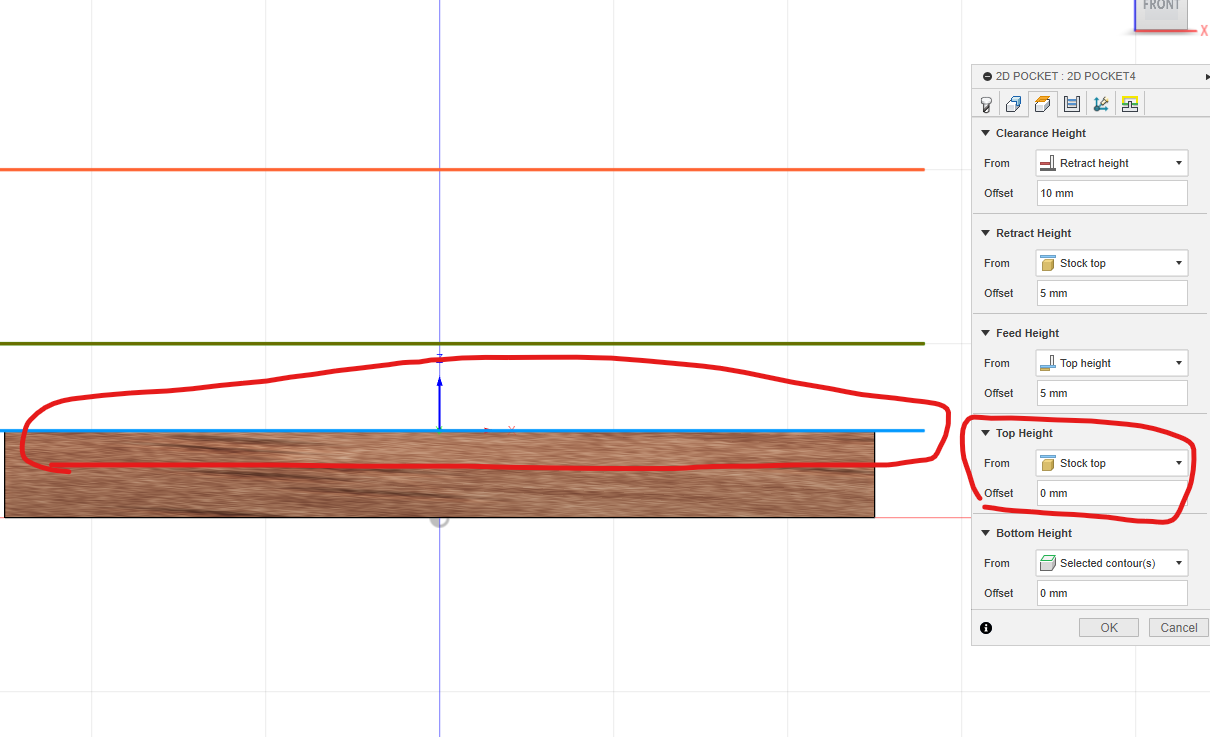
Leave the Heights tab at its defaults, but confirm that Top Height is the plaque's top surface.
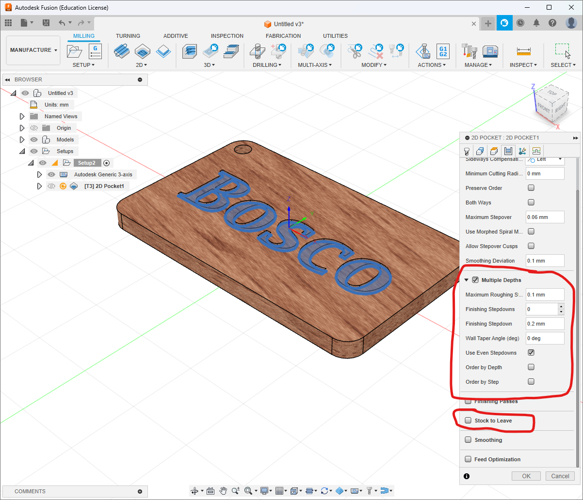
On Passes, enable Multiple Depths, confirm the 0.1 mm stepdown and disable Stock to Leave.
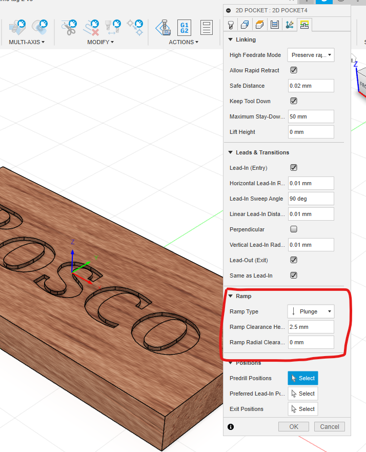
On Linking, set Ramp Type to Plunge, leave the other values at their defaults and click OK.
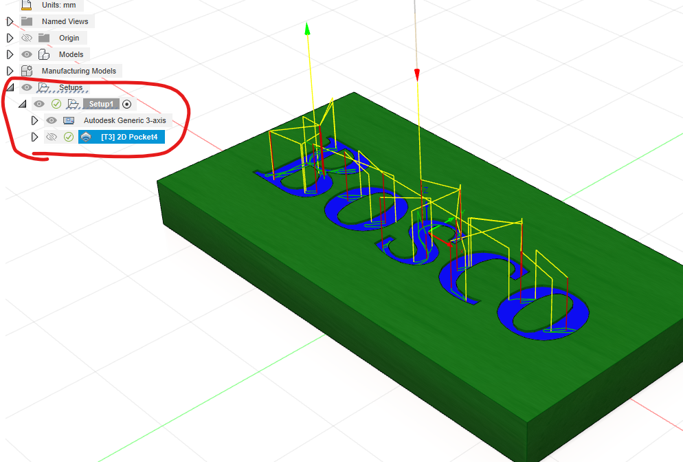
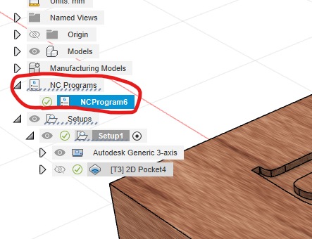
The generated operation should show a green check in the Browser. Blue and yellow lines over the part are the toolpath and linking moves.
2.4 Export the Toolpath
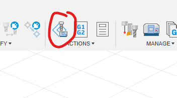
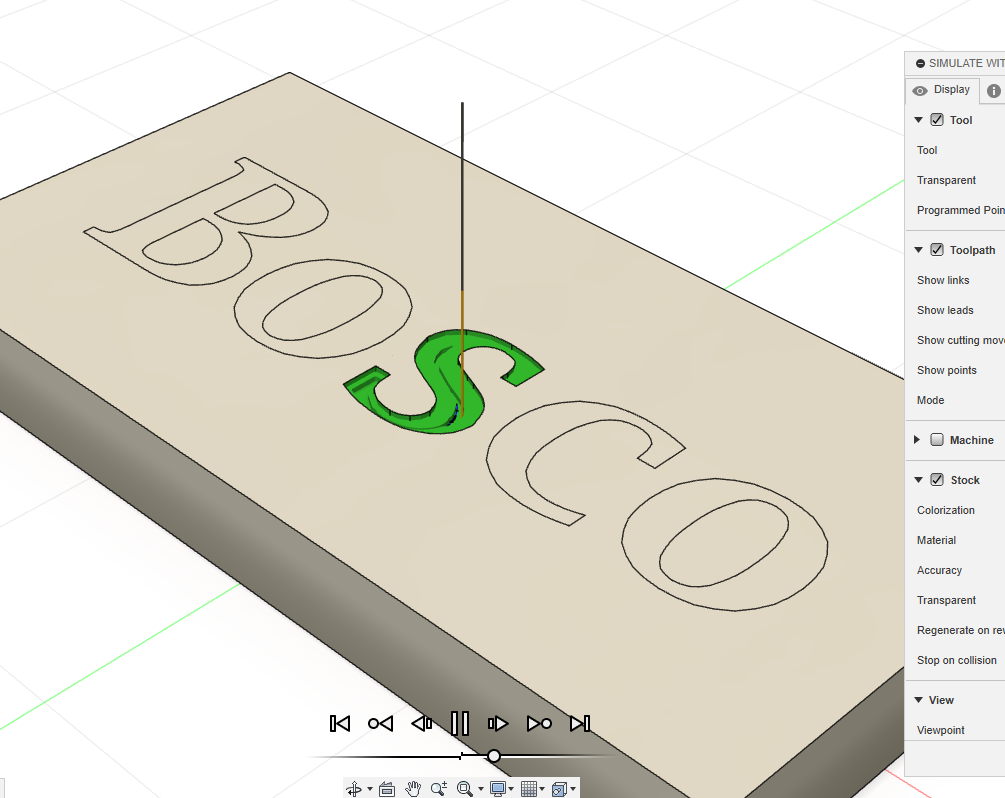
Run Simulate with Machine from Actions and watch the entire process for incorrect order, depth or collisions.
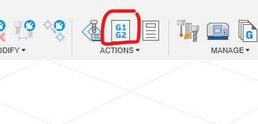
Choose Post Process. A post-processor translates generic CAM operations into the dialect expected by the machine controller. This machine uses GRBL, a widely used open-source CNC controller.
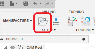
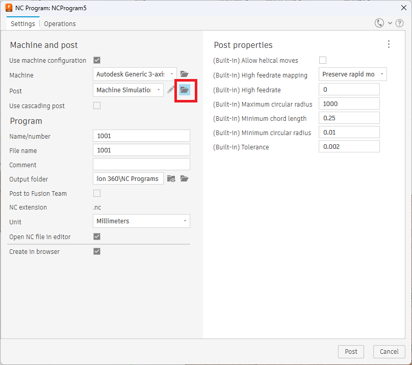
Open the Post library using the folder icon.
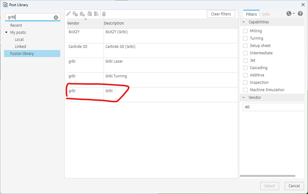
Search for grbl, select grbl - Grbl, and copy/select it for the local library.
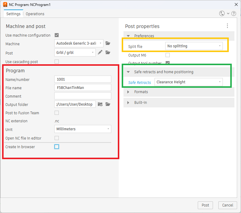
Configure:
Name/number: identify the machining operation.File Name: use a descriptive project name.Output folder: choose a convenient location.Split file: if a later job changes tools, chooseSplit by toolbecause this machine has no automatic tool setter.Safe Retracts: chooseClearance Height.- Click
Postto generate one or more.ncfiles.
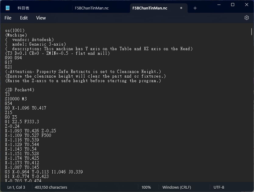
Opening the result in a text editor shows that G-code is a sequence of machine and coordinate commands. Fusion keeps the CAM operations in the Browser; if the model changes, regenerate the toolpaths instead of rebuilding every setting.
3. Machine the Part
3.1 Power-Up and Manual Control
⛔️DANGER
Before switching on:
- Make sure the red
E-Stopis pressed. - Turn
Spindle Speedto its minimum. - Wear the required eye protection and follow the workshop supervisor's instructions.
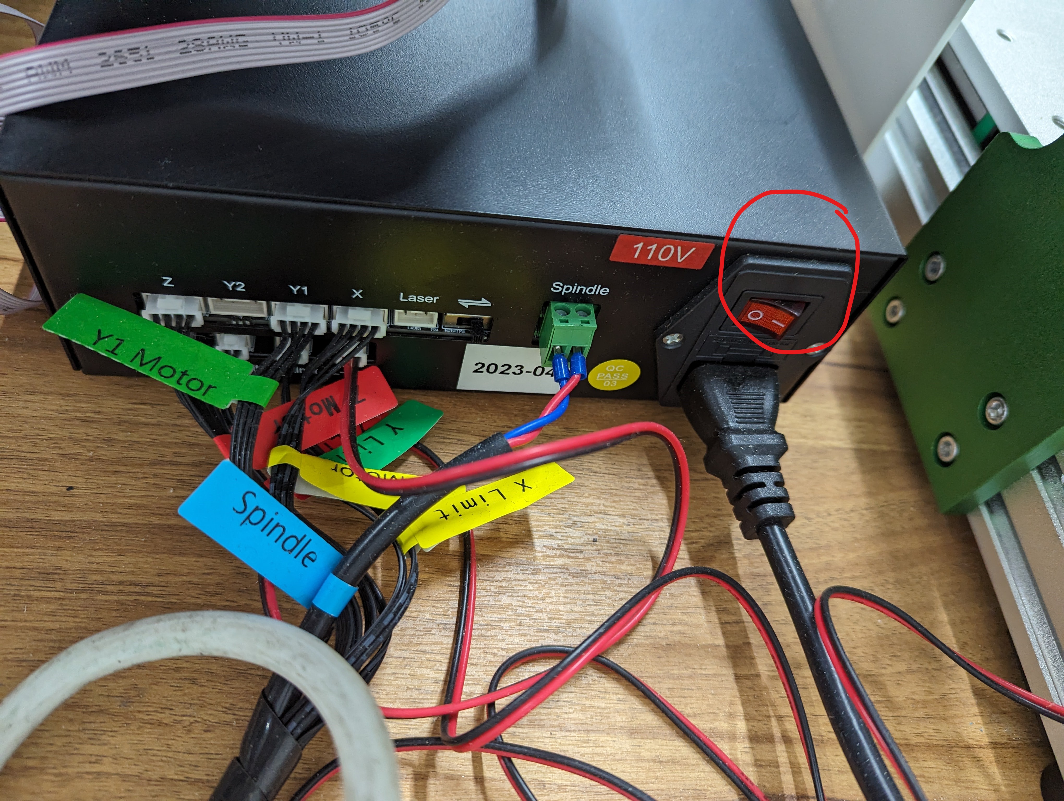
The power switch is on the rear of the enclosure, above the power cable.
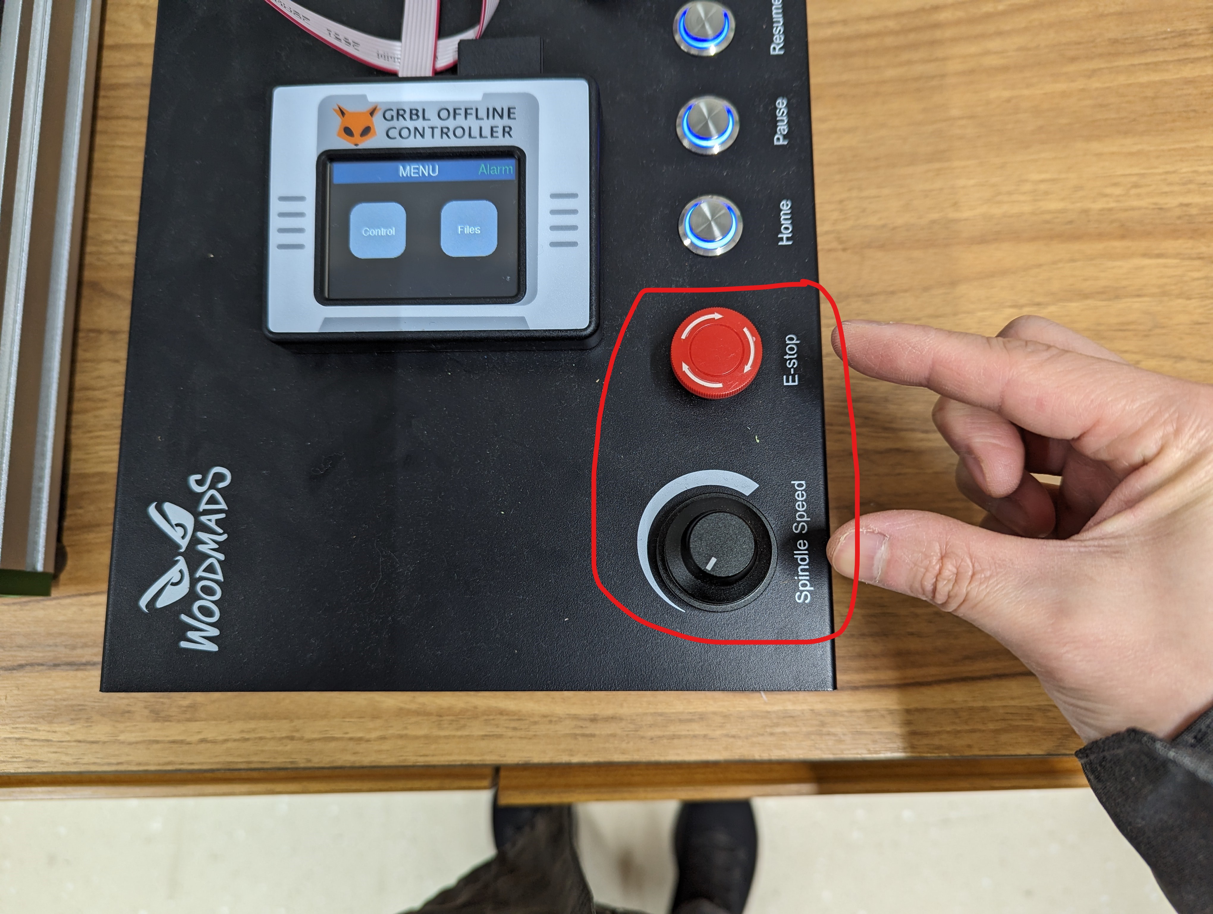
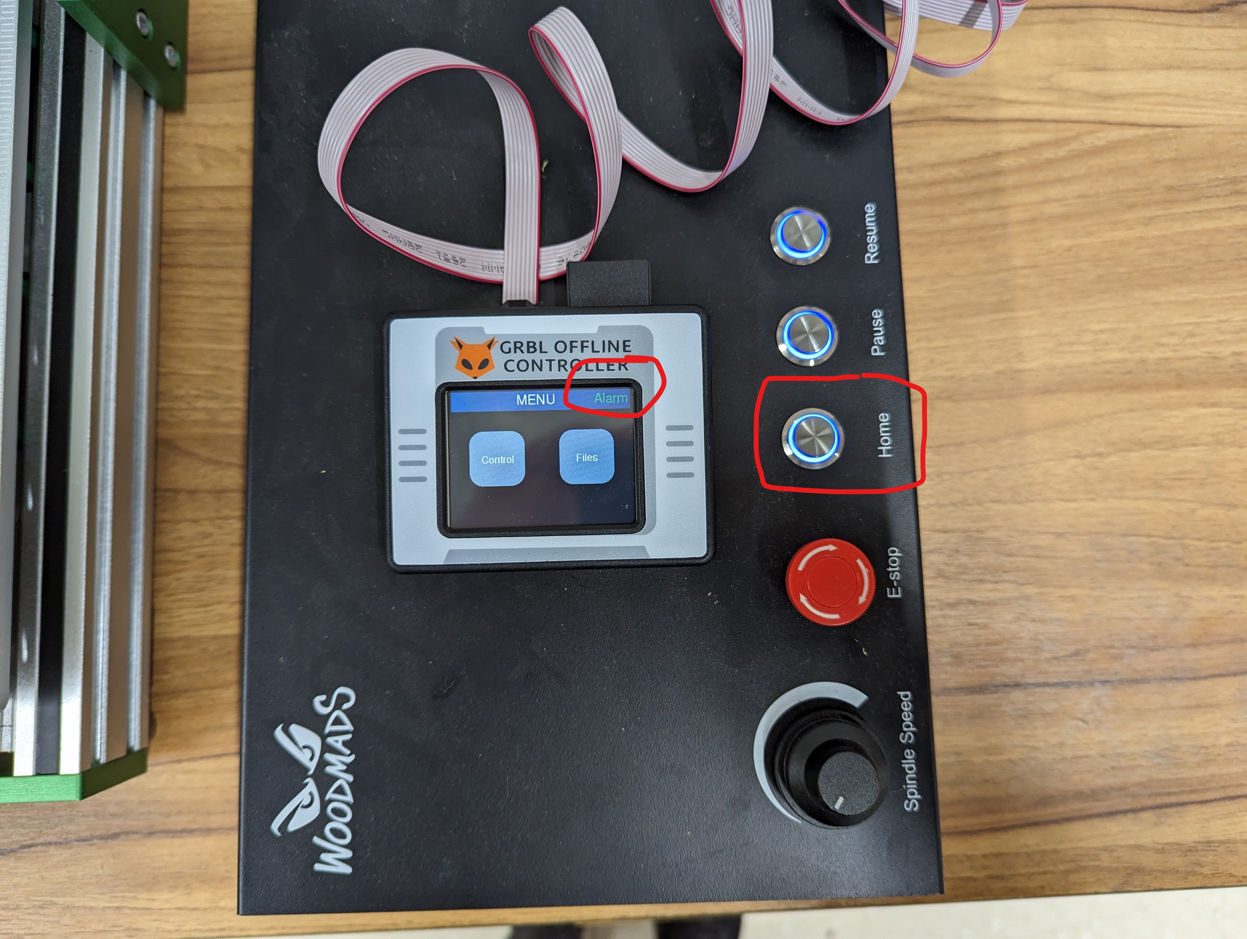
After power-up, the offline controller shows Alarm. Press Home before attempting to move the machine.
⚠️WARNING
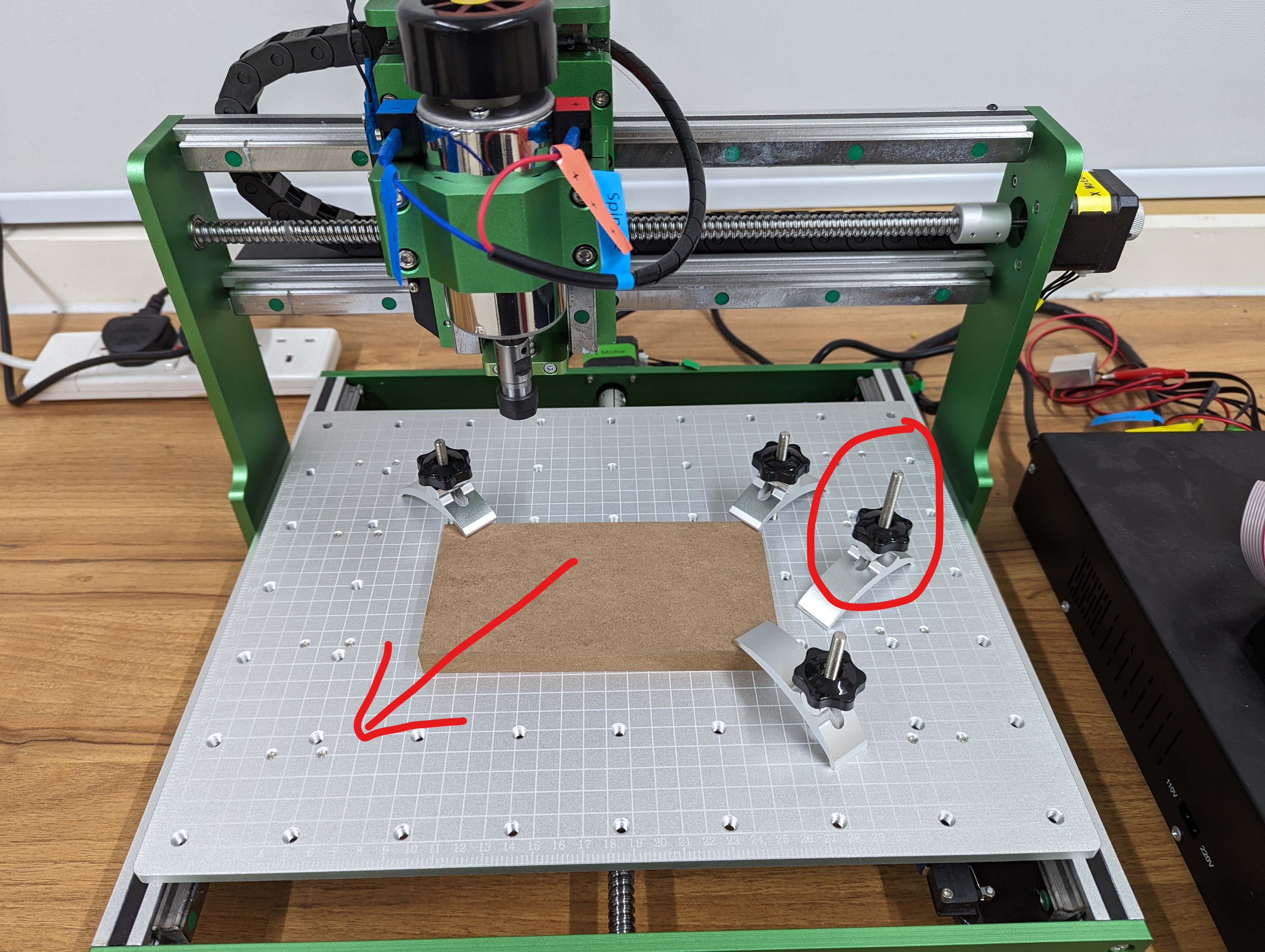
The machine homes towards the lower-left corner. Do not install the lower-left clamp until homing has finished.
When homing is complete the status becomes Idle. Open Control, then Move.
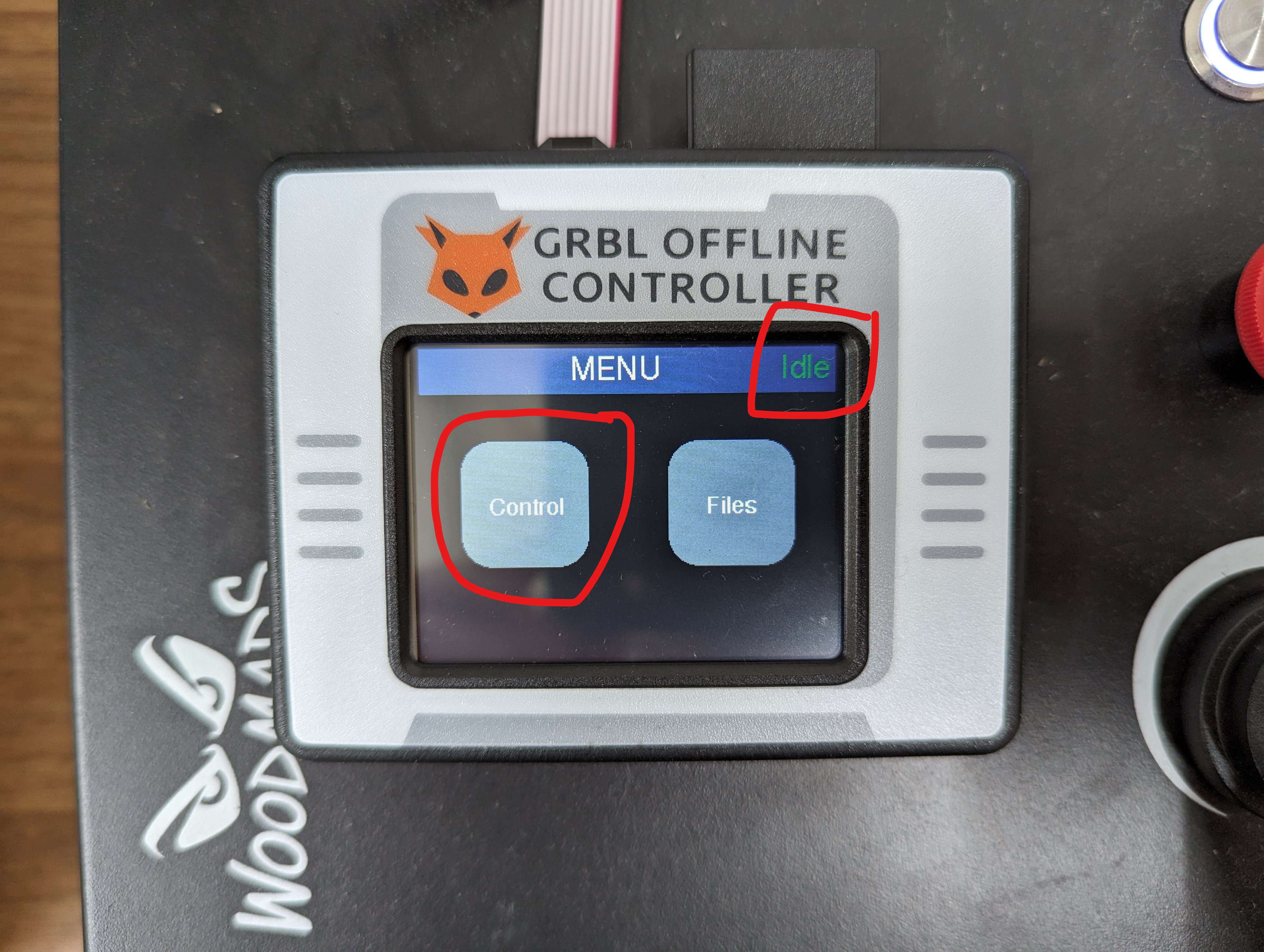
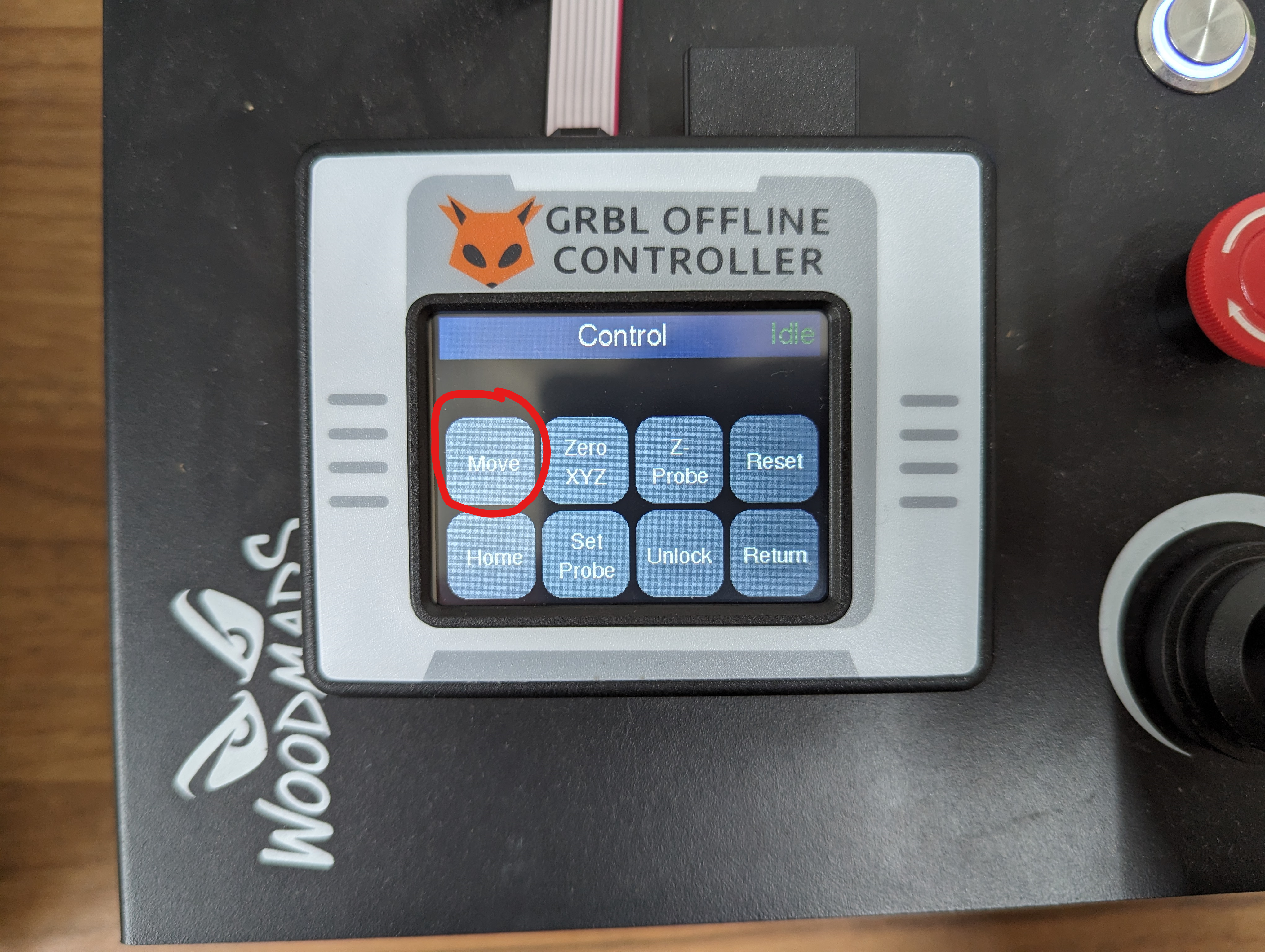
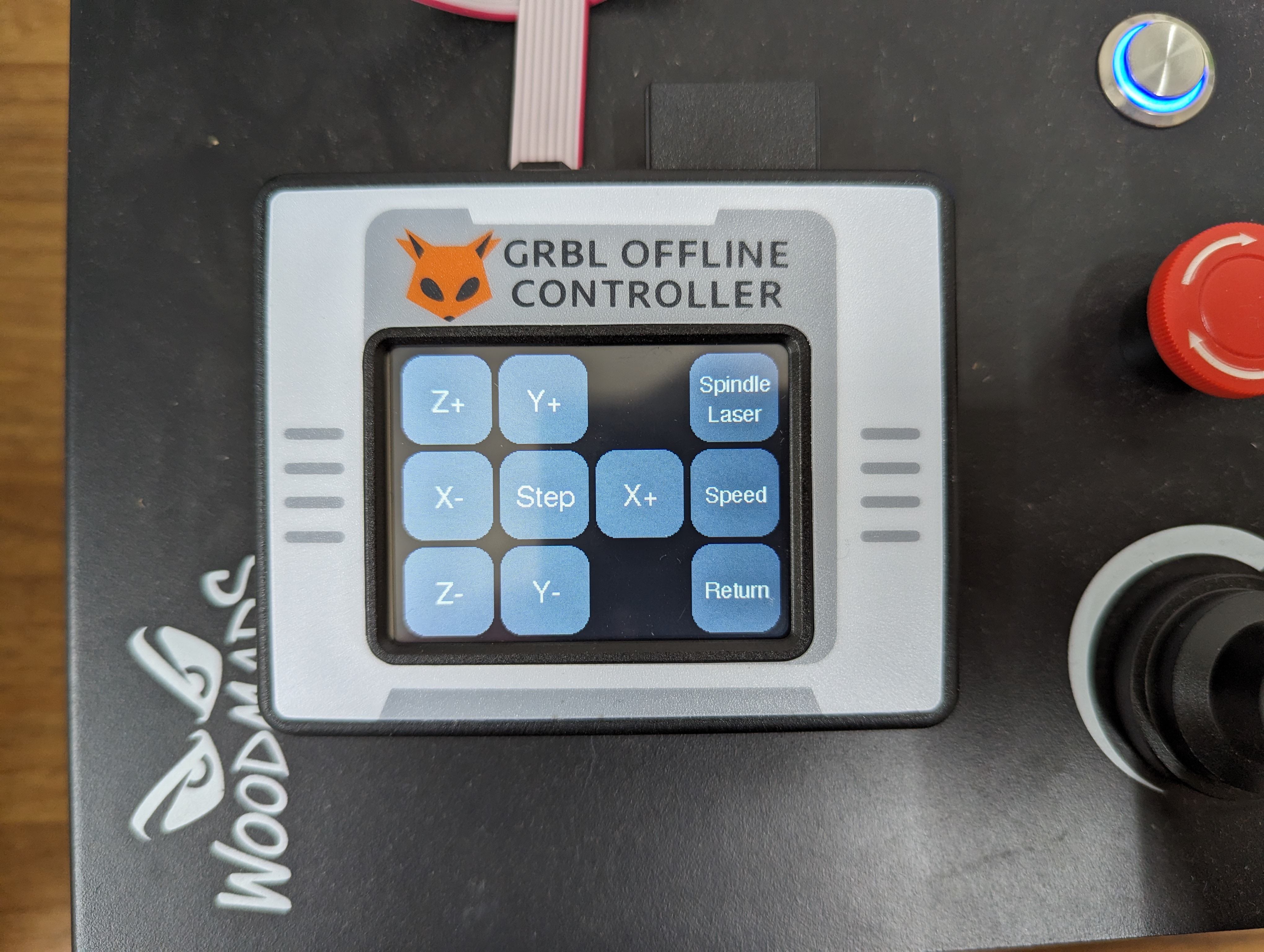
The positive and negative X/Y/Z buttons jog each axis. In continuous Step mode a button can be held for fast movement; press Step to cycle through 0.05, 0.1, 1 and 10 mm increments for precise positioning.
3.2 Set the Work Origin
Tool setting establishes the real position of the stock and tool relative to the CAM coordinate system.
Method 1: Paper
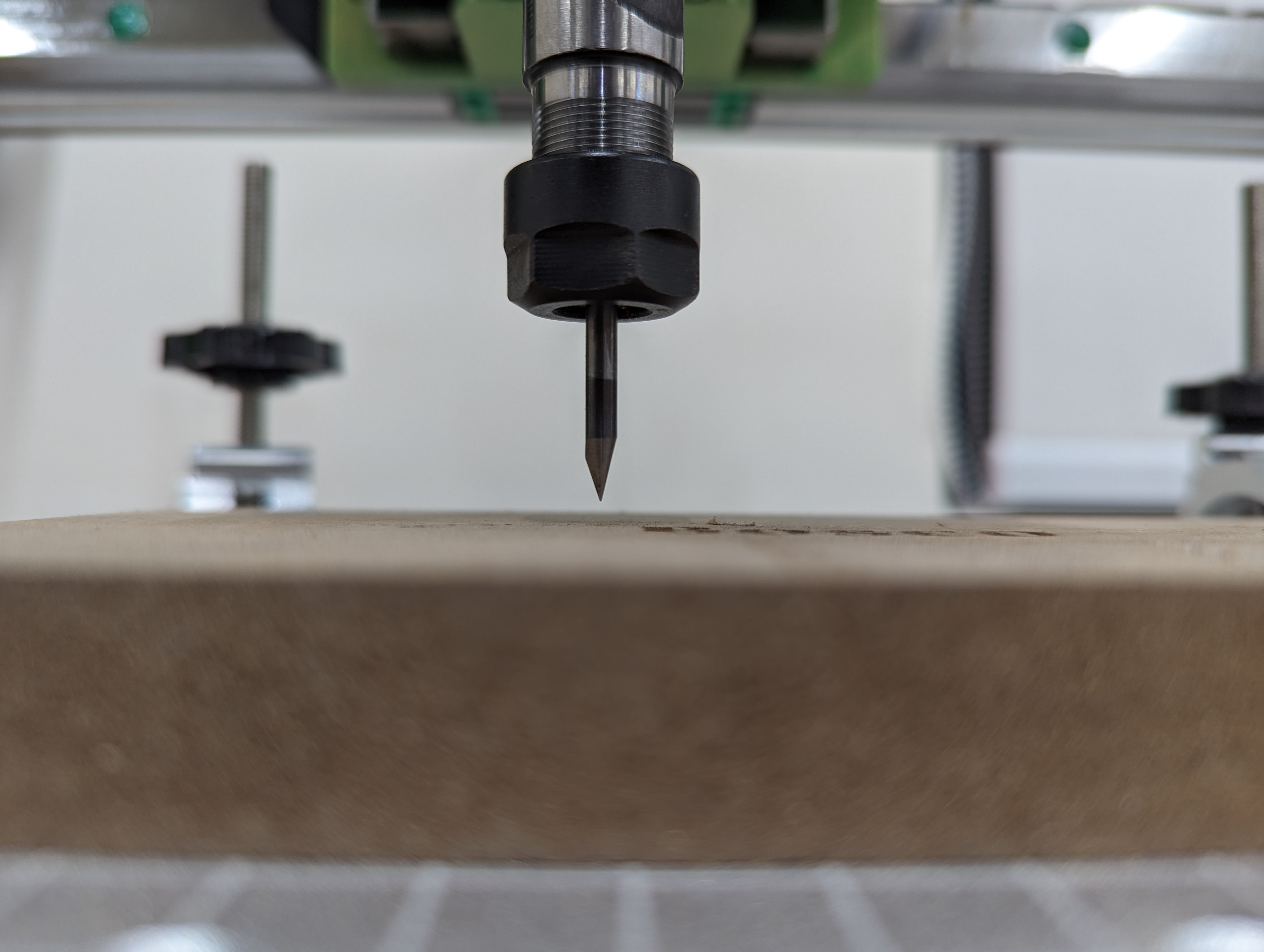
Move the tool close to the workpiece surface.
⛔️DANGER
As the tip approaches the surface, change to 0.05 mm/step. A larger step can drive the fragile tip directly into the material.
Place ordinary A4 paper between tool and stock. Lower the tool in 0.05 mm steps while sliding the paper gently. Stop when the paper is just held and can no longer move.
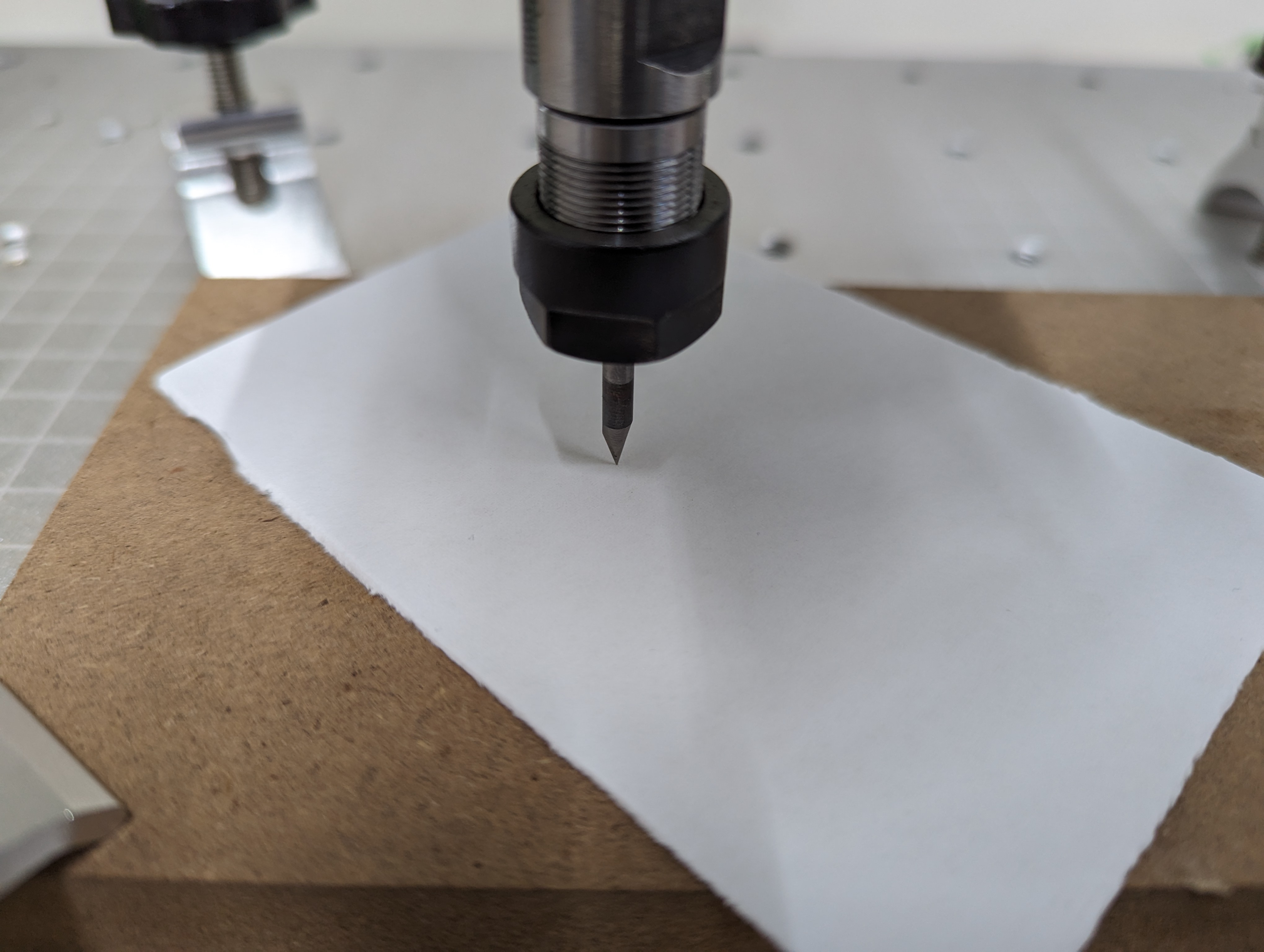
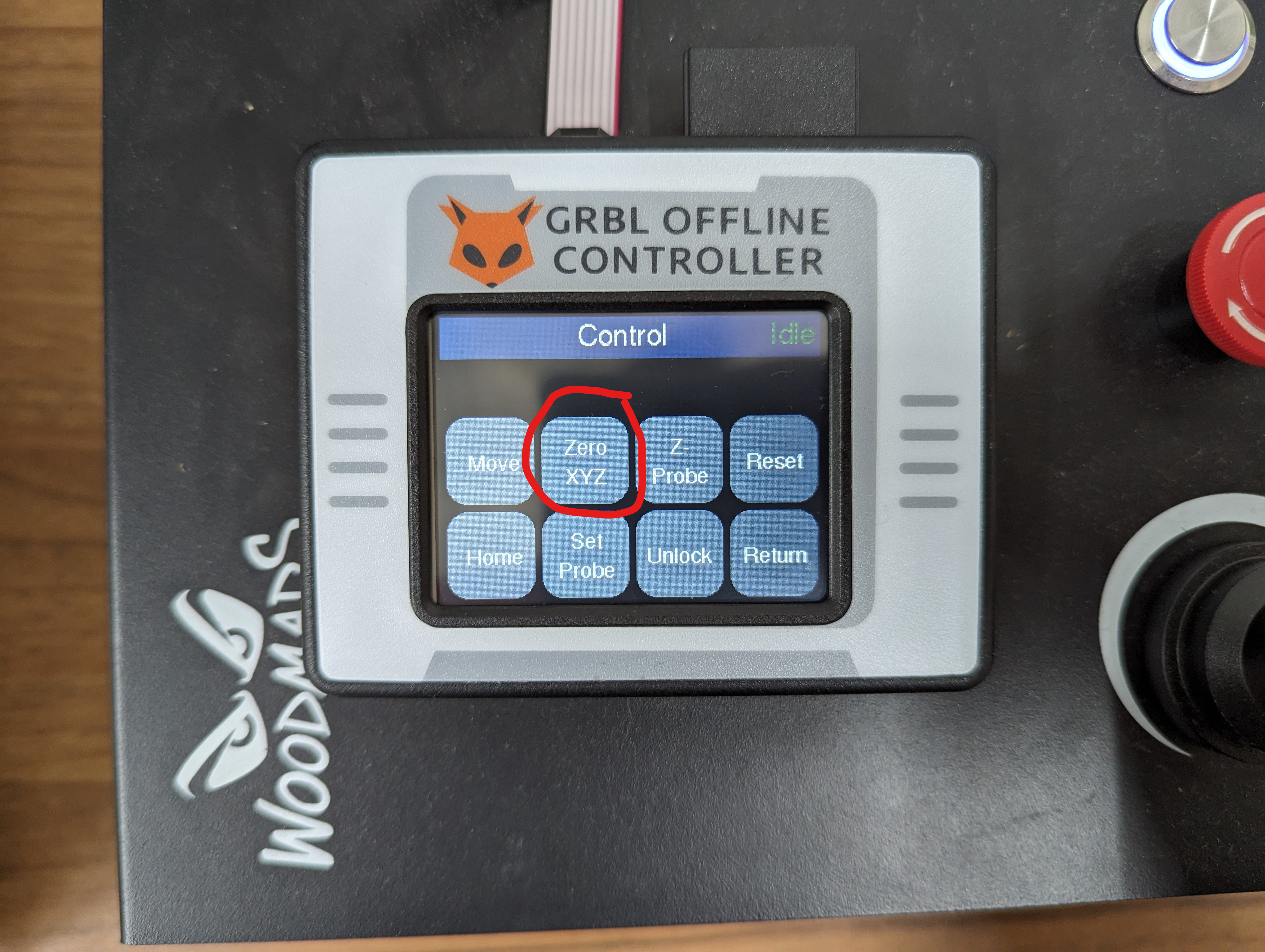
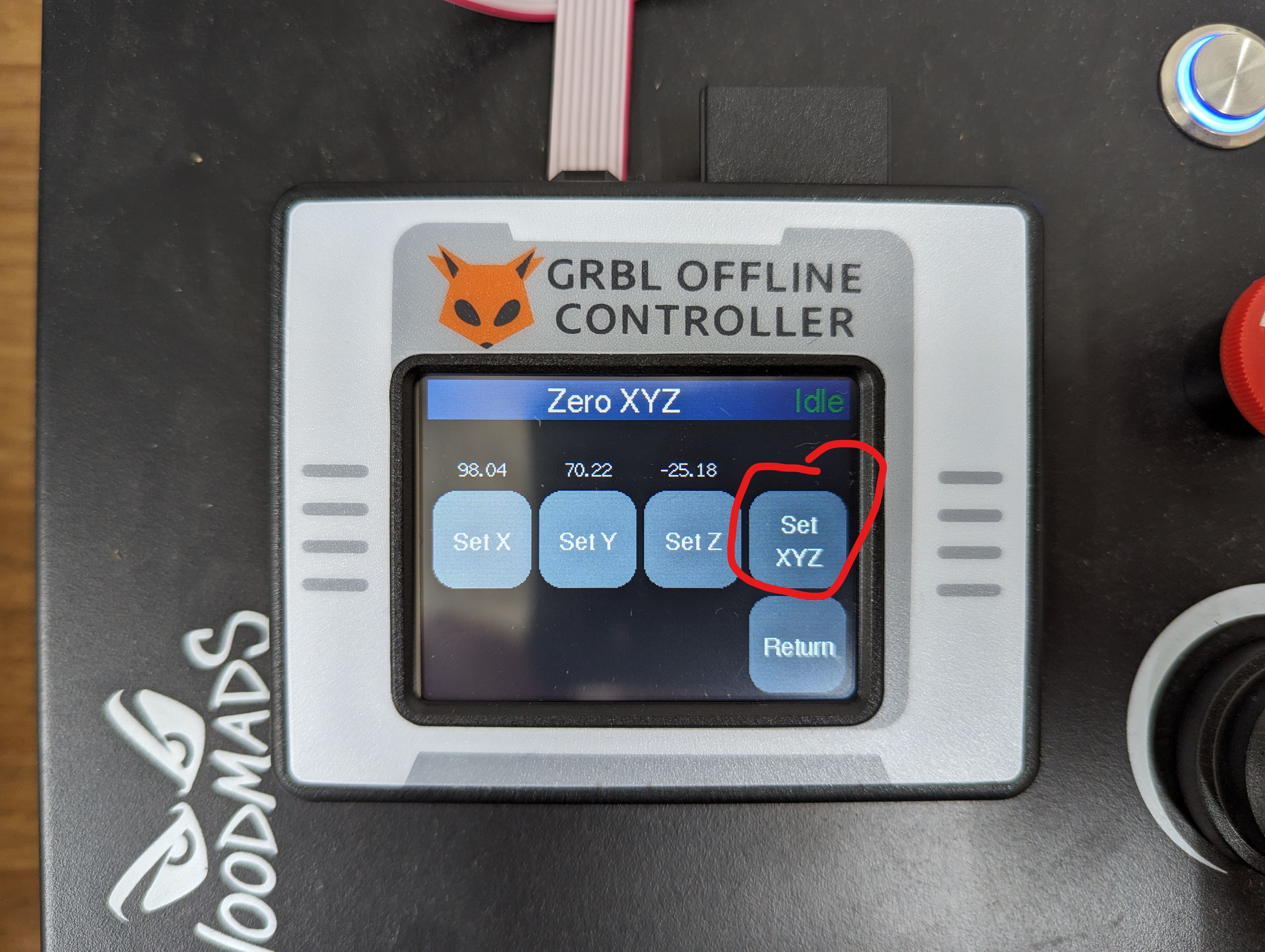
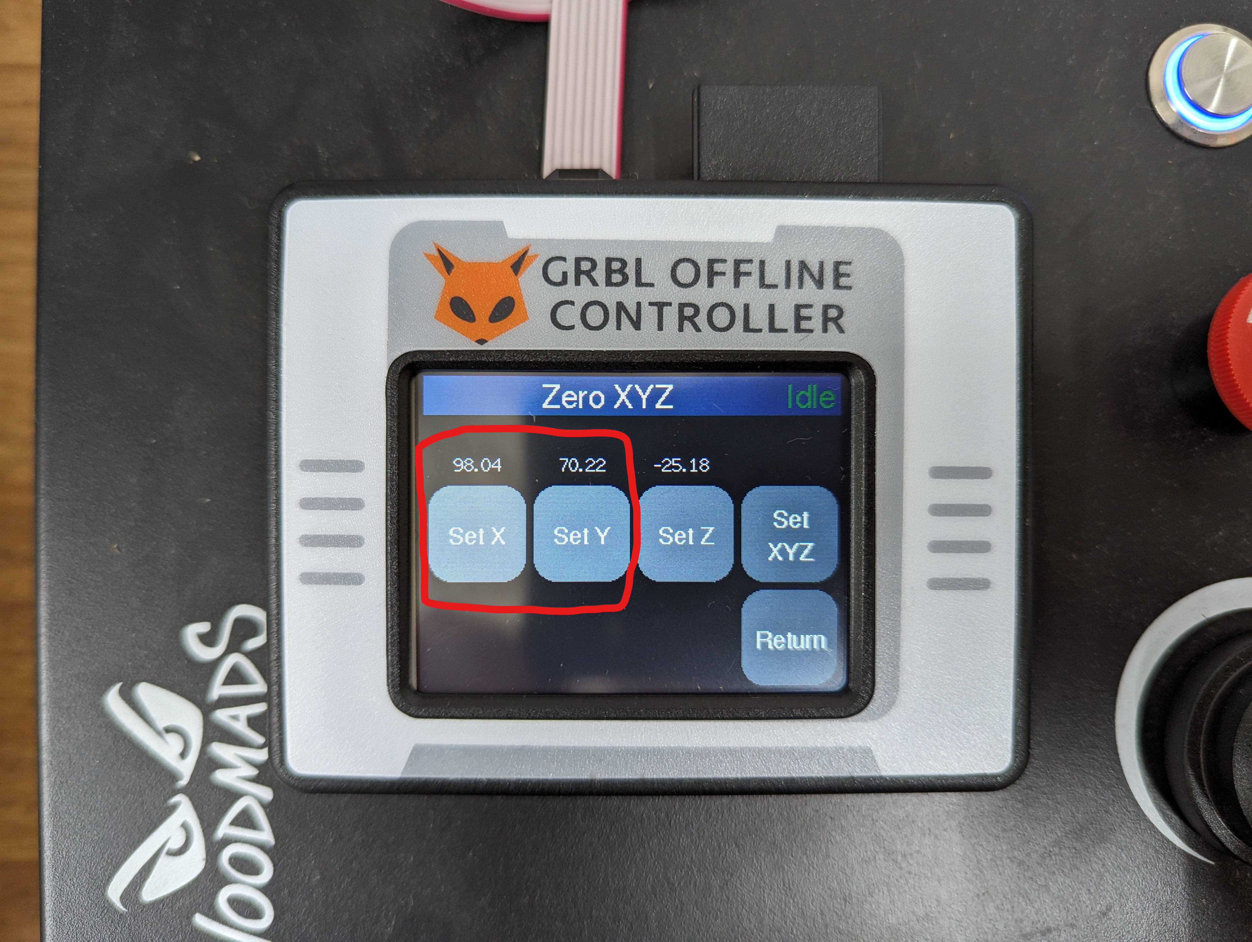
Return to the main screen, choose Zero XYZ, then Set XYZ. Raise Z after zeroing so that the program cannot begin an XY move with a stationary tool touching the stock.
Method 2: Touch Probe
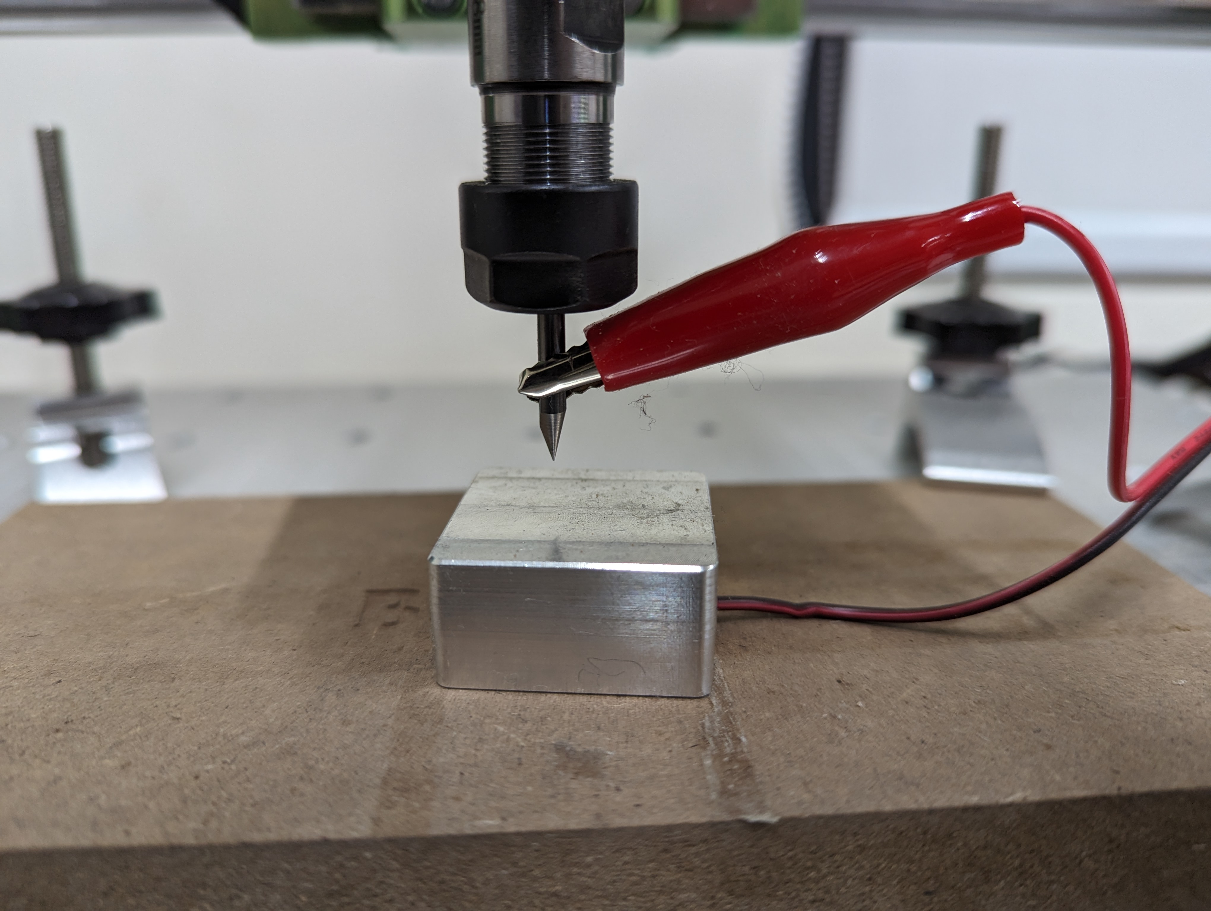
Turn Spindle Speed to its minimum. Place the 15 mm touch plate between tool and stock and attach the crocodile clip to the tool so contact completes the probe circuit.
Download z probe Z15.nc, or save the following as an .nc file:
G21 G91 G38.2 Z-30 F80
G0 Z1
G38.2 Z-2 F10
G92 Z15
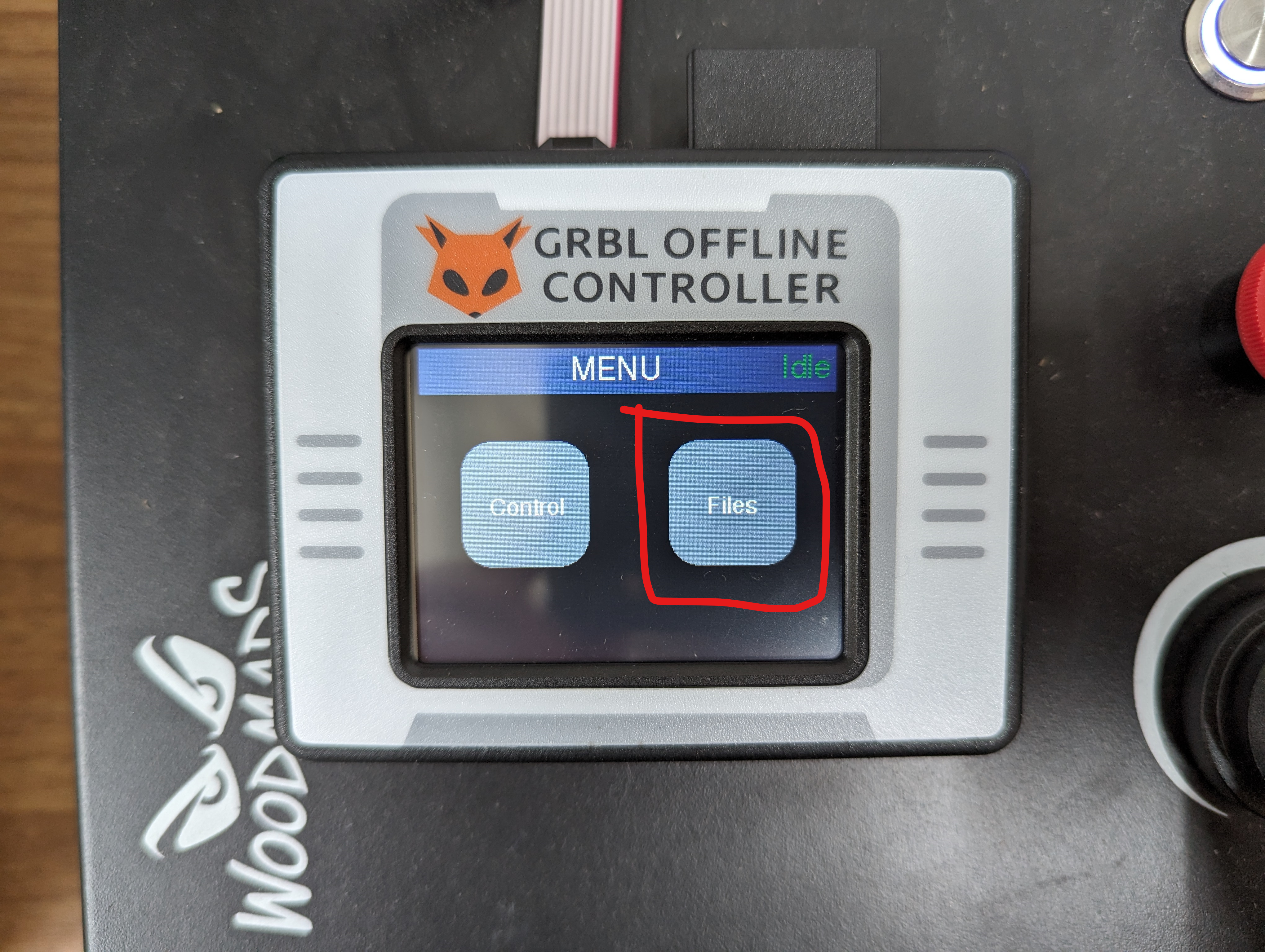
G0 Z5The program probes down, retracts 1 mm, probes slowly for a more precise contact, sets that position to Z = 15 mm because the plate is 15 mm thick, then raises the tool 5 mm. Copy it to the SD card, choose it under Files and press Send.
⚠️WARNING
This routine resets Z only. Jog to the required XY origin and reset X and Y manually in Zero XYZ. Verify the probe wiring and be ready to stop the machine before running an unfamiliar probing routine.
3.3 Machine the Nameplate
- Copy the Fusion-generated G-code file to the SD card.
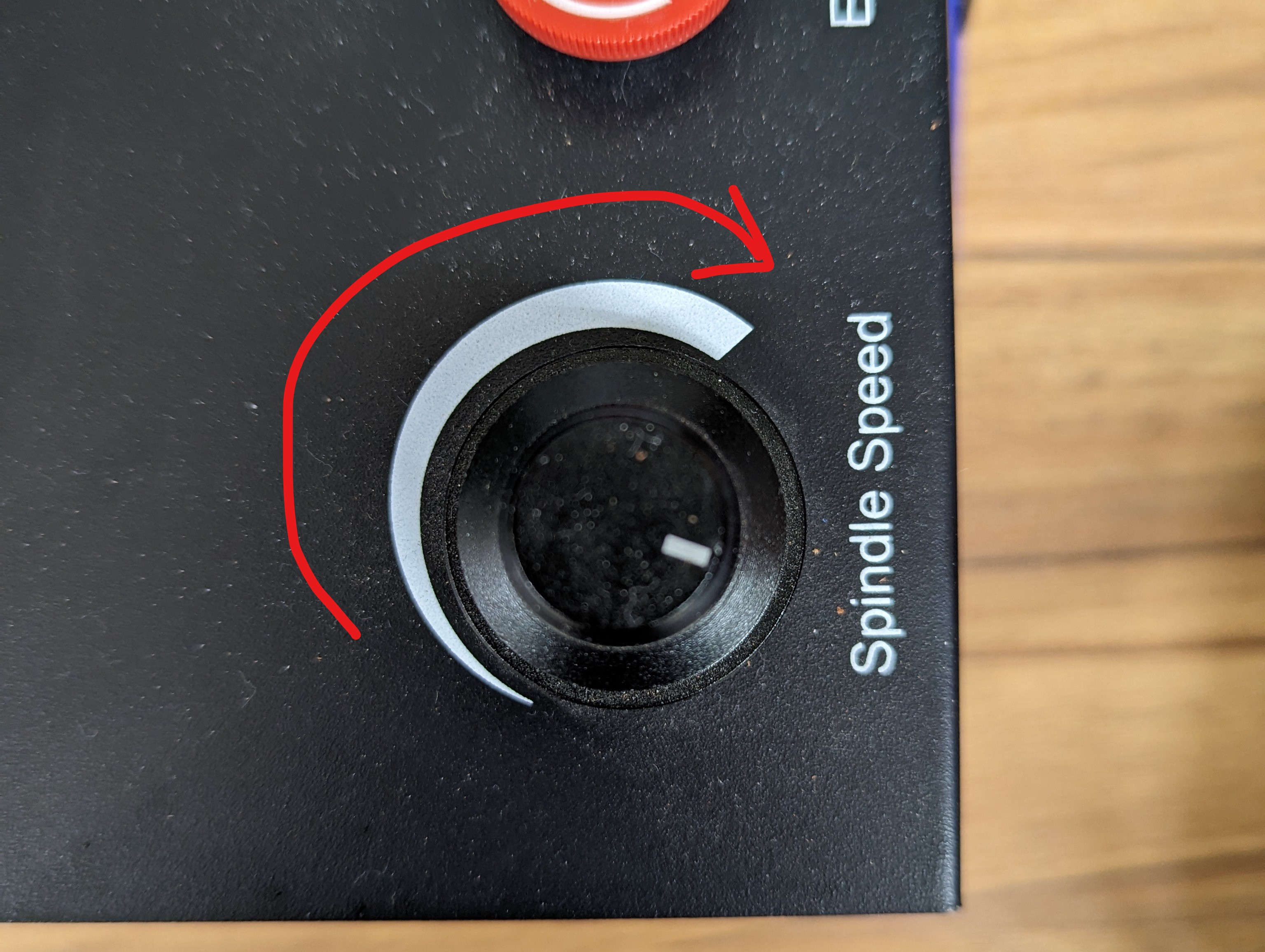
- Return to the machine and set the demonstrated spindle control to its required operating speed.
- Choose the file under
Files, verify the origin and clearances once more, then pressSend. - The example job takes approximately 16 minutes.
⛔️DANGER
Never leave a CNC machine unattended. Keep clear of moving parts and chips, and press the red E-Stop immediately if anything behaves unexpectedly.
Translation notice: This English page was generated automatically by AI and has not yet been reviewed by a human. It will be checked and revised page by page when time permits.